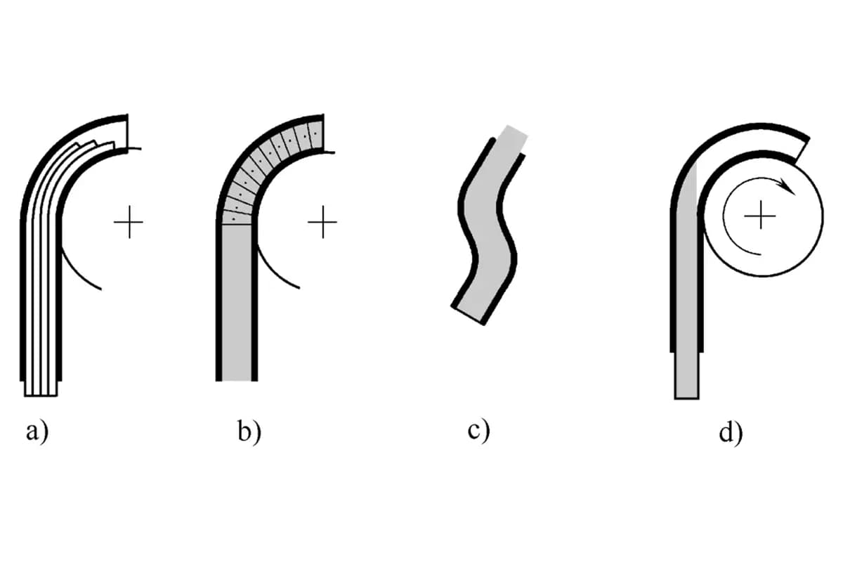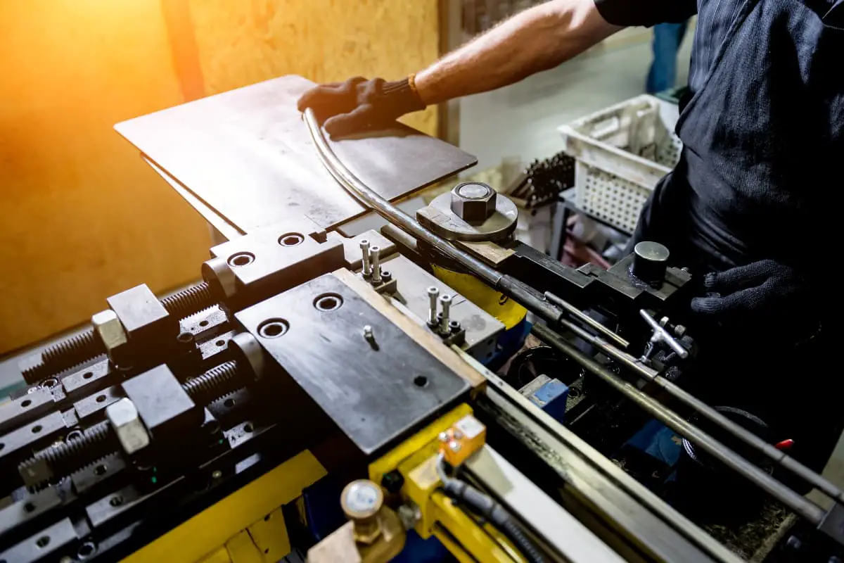
There are many methods of bending pipes, which can be divided into press bending, draw bending, push bending, roll bending, and roll forming according to the bending method; into cold bending and hot bending according to whether it is heated during bending; and into core (filler) bending and coreless (filler) bending according to whether there is filler during bending.
Sometimes, to meet the specific shape requirements of pipe fittings, or to reduce the difficulty of bending processing, other special bending methods are also used, such as crimp bending method, etc. The summary of various bending process methods is as follows.
1. Classification by bending method
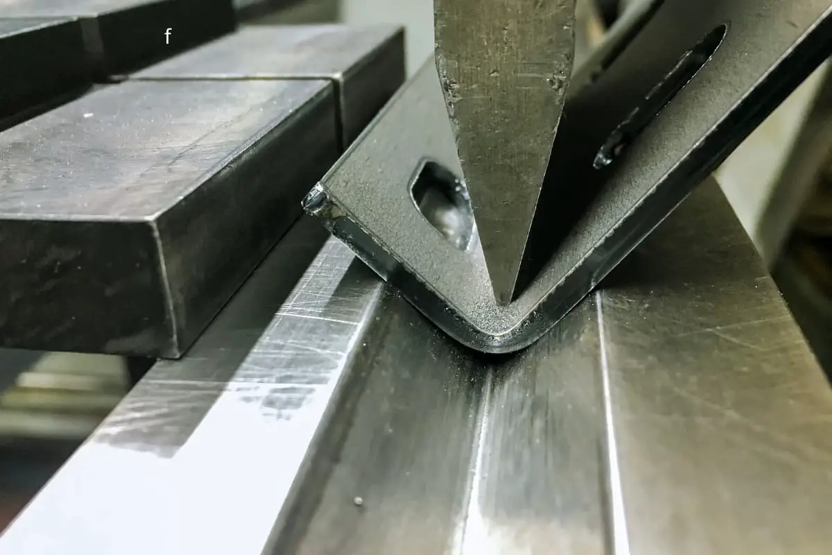
(1) Press bending
Press bending is the earliest process method used for pipe bending. It involves bending the pipe blank on a hydraulic press or mechanical press using a mold or mandrel. The principle of press bending is shown in Figure 4-10. The press bending method can be used to bend pipe fittings with straight sections as well as elbows. Currently, press bending is mainly used for pressing elbows and has been widely applied in elbow production.
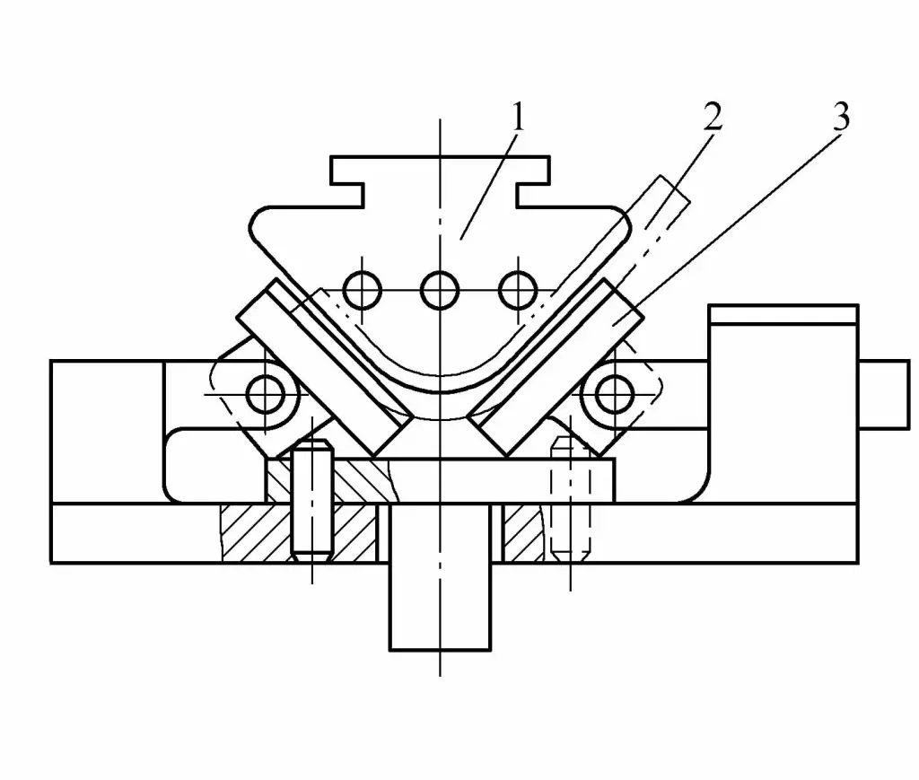
1—Punch
2—Billet
3—Swinging concave die
(2) Pull bending
Pull bending is the method of pressing the tube against a fixed convex die, applying axial tensile force F and bending moment to both ends of the tube at the same time, so that the tube is formed along the convex die, as shown in Figure 4-11. In general bending forming, the maximum bending angle is about 180°.
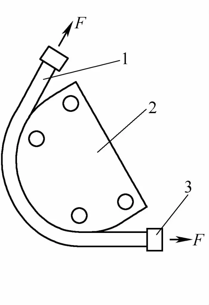
1—Pipe fittings
2—Fixed bending plate
3—Fixed mold
During bending, the tube is subjected to axial tensile force while bending to overcome the wrinkling on the inside and improve the stress distribution inside the section, reduce springback, and improve the accuracy of the shape. Compared with other bending processes, bending forming has the following characteristics:
1) Can form parts with complex spatial structures.
2) Can bend parts with a larger shape and strength ratio.
3) High bending accuracy, small springback.
4) Can effectively eliminate the residual stress inside the bent material, good product size stability.
5) Due to the cold hardening of metal materials, the comprehensive mechanical properties of the material can be improved after stretch bending.
However, the stretch bending method is difficult to maintain the cross-sectional shape of the bent blank, mainly suitable for open-section profiles with force-supporting parts, and this method is not suitable for forming thin-walled tubes.
(3) Push bending
Push bending is to place the tube to be bent into the guide sleeve of the bending mold first, under the pushing force of the punch, the tube blank is in a state of compressive stress, and in the process of passing through the die, it is bent into the required curvature shape, as shown in Figure 4-12.
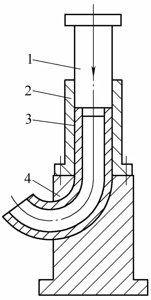
1—Pressure column
2—Guide sleeve
3—Billet
4—Bending mold
Push bending is a bending process carried out on a general press, hydraulic press, or special pushing machine, mainly used for bending elbows. However, the push bending method requires passing through the bending die entirely, so this method cannot make elbows with straight sections, and it is also not suitable for bending pipes with small bending radii.
According to the characteristics of the push bending process, it can be divided into two types: cold push bending with a mold and hot push bending with a mandrel. Cold push bending with a mold is to press the billet into a mold with a bending cavity at room temperature, thereby forming a pipe elbow.
Hot push bending with a mandrel is carried out under the action of thrust and the resistance of the bullhorn mandrel, heating while pushing, causing the billet to undergo circumferential expansion and axial bending deformation, thus pushing the smaller diameter billet into a larger diameter elbow. The working principle is shown in Figure 4-13.
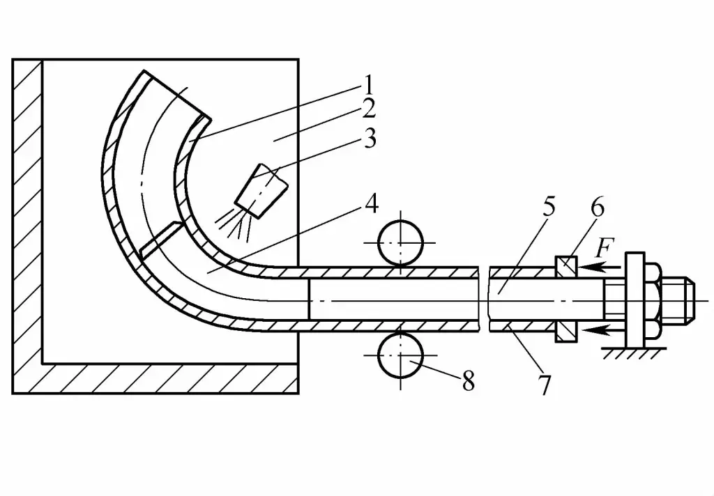
1—Elbow
2—Reflection heating furnace
3—Heat source
4—Bullhorn mandrel
5—Core rod
6—Push plate
7—Pipe blank
8—Supporter
(4) Wrap bending
Bending is a processing form where the active die revolves around the fixed bending mold to perform bending, divided into compression mode and stretching mode, as shown in Figure 4-14. The main difference between the two methods is whether the punch rotates with the tube material. The method where the punch does not rotate with the tube material is the compression mode, otherwise, it is the stretching mode. This method has relatively large cross-sectional distortion and is also not suitable for forming thin-walled tubes.
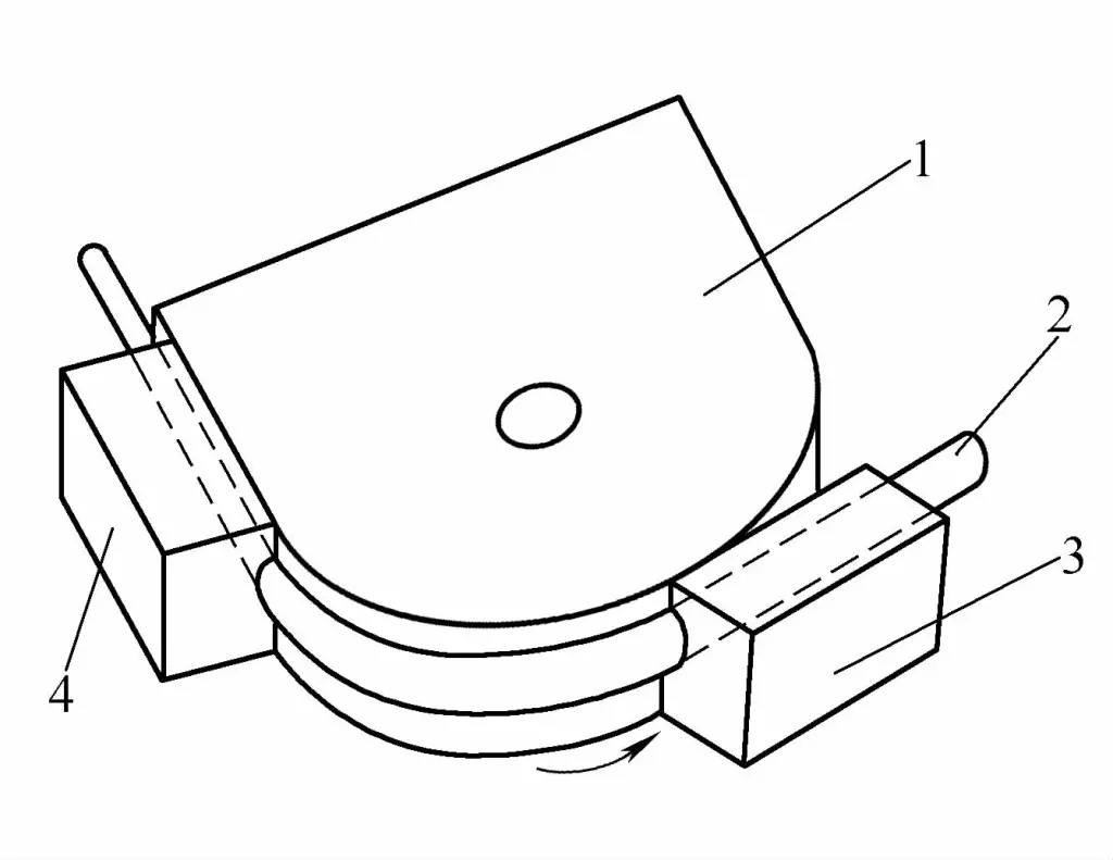
1—Fixed punch
2—Pipe fitting
3—Rotating die
4—Tighten the concave mold
Bending is divided into manual bending and machine bending.
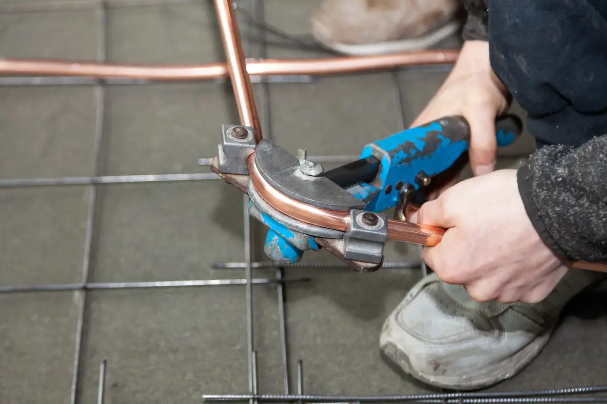
Manual bending is the process of bending the pipe blank using a simple bending device. Depending on whether heating is applied during bending, it can be divided into cold bending and hot bending. Generally, for small diameter (pipe blank diameter D≤25mm) pipe blanks, due to the smaller bending torque, cold bending is used; while larger diameter pipe blanks are mostly hot bent. Manual bending does not require specialized bending equipment, the manufacturing cost of the bending device is low, and it is convenient to adjust and use, thus it is suitable for small batch production without specialized bending equipment. The disadvantage is that it requires a lot of labor and has low productivity.
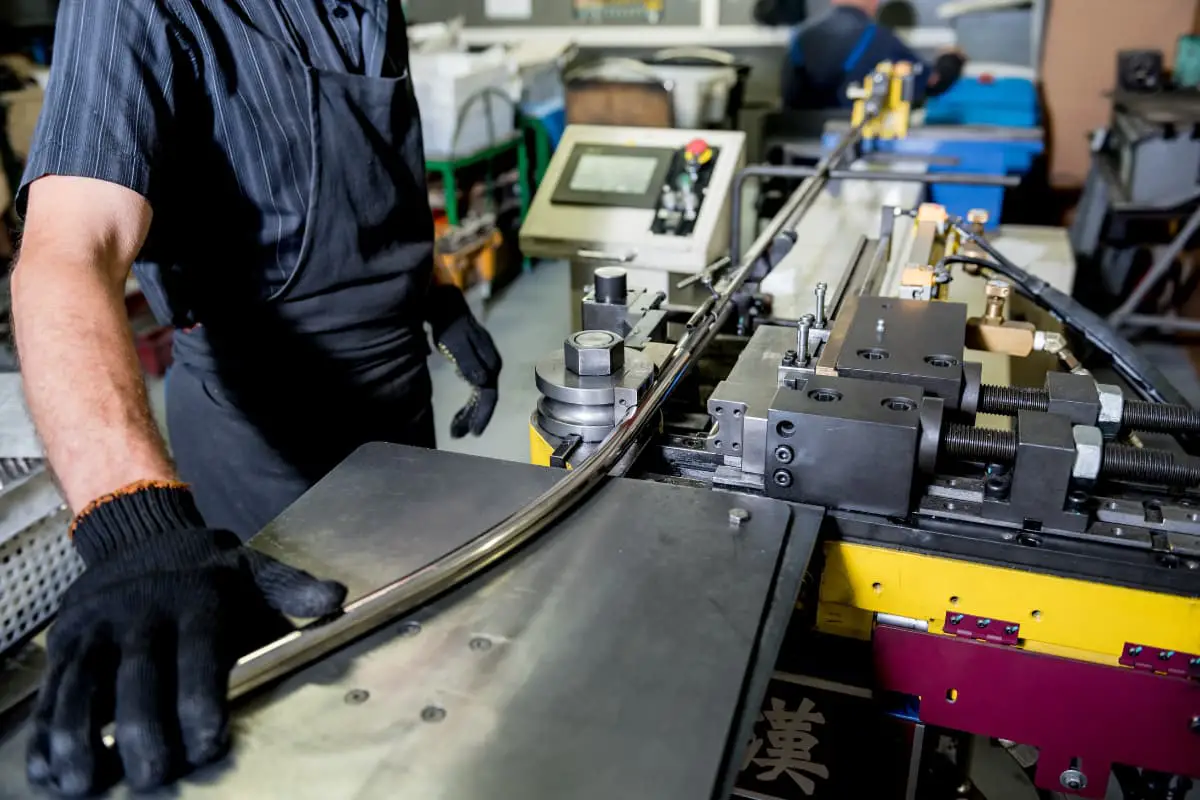
Machine bending is bending processing performed on a vertical or horizontal bending machine. According to its process characteristics, it can be divided into three types: mandrel bending, mandrel-less bending, and push bending. Since machine bending is performed in a cold state, this type of bending machine is also called a cold bending machine. During machine bending, the pipe blank is not filled with material, but is bent using a mandrel or without a mandrel, which results in high production efficiency and good bending quality, hence it is widely used in mass production.
(5) Roll bending
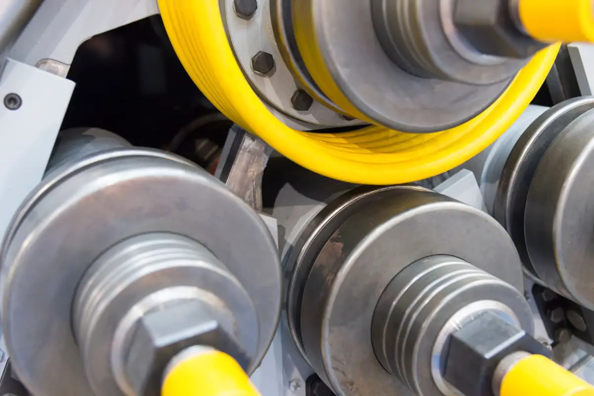
Roll bending is the process of bending the pipe material using three or four driven rollers, as shown in Figure 4-15. The working principle of the roll bending method is basically the same as that of plate roll bending, the only difference being that the rollers used for pipe roll bending have working surfaces that match the cross-sectional shape of the bent pipe blank.
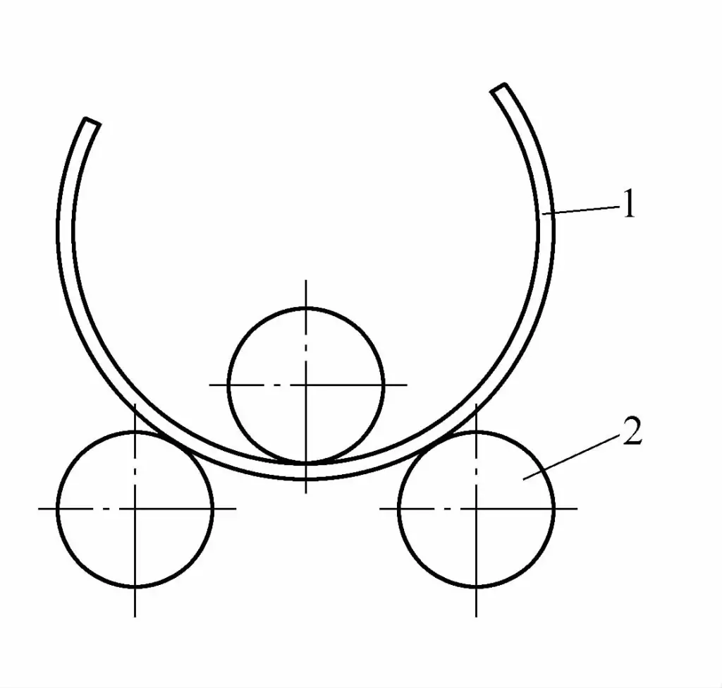
1—Bent part
2—Drive roller
By changing the spacing between the rollers, bending of any curvature radius can be achieved. The roll bending method has certain limitations on the bending radius, and is only suitable for thick-walled pipe parts that require a large curvature radius, especially convenient for bending ring-shaped or spiral-shaped pipe parts.
2. Classified by the presence or absence of molds
(1) Molded bending
The bending deformation area of the tube blank is directly acted upon by the rigid mold, including common methods such as press bending, draw bending, push bending, roll bending, etc. The characteristics are high repeatability and fast speed. To improve the bending accuracy, it is usually necessary to adjust the shape and size of the working part of the rigid mold to compensate for the springback that occurs after the part is unloaded. The amount of compensation is difficult to calculate accurately and often needs to be determined by experience.
(2) Moldless bending
The bending deformation area is not directly acted upon by a rigid mold, and the final shape of the tube is determined by the relative movement of the tool and the workpiece. Laser bending belongs to moldless bending.
3. Classified by whether heating is applied
(1) Cold bending
Cold bending refers to the processing technology of bending the tube at room temperature with mechanical force. Since work hardening occurs in the metal during cold bending, the metal tube after cold bending is much harder than the metal tube after hot bending, but cold bending does not destroy the original properties of the metal.
After cold bending, it is not necessary to clean and remove the oxide skin, and thermal deformation does not occur. Compared with hot bending, cold bending consumes more bending power, and both springback and residual stress are significantly increased. Moreover, cold bending cannot bend very small radius sharp bends.
(2) Hot bending
The processing technology that heats the pipe fitting to the specified bending temperature of the pipe fitting before bending it. Hot bending has an adaptability that cold bending cannot compare with. For example, the straight distance between two adjacent elbows on a pipe can be kept very small, or even continuous bending can be performed without leaving a straight pipe section interval; materials with poor cold ductility can be processed into elbows; elbows that require a lot of mechanical energy during cold bending can be processed, and brittle materials that are prone to cracking during cold bending can be bent into shape.
Hot bending can bend small radius elbows on pipes. For carbon steel pipes and most alloy steel pipes, the bending radius of hot bending is much smaller than that of cold bending, and the bending radius can be as small as 0.7 to 1.5 times the outer diameter of the pipe. However, hot bending has the following disadvantages: complex equipment, high processing costs, low production efficiency, and high surface roughness values. For copper pipes, the cold bending process is used, and since high-temperature heating is avoided, the possibility of “hydrogen disease” is eliminated.
4. Classification of CNC numerical control pipe bending processes
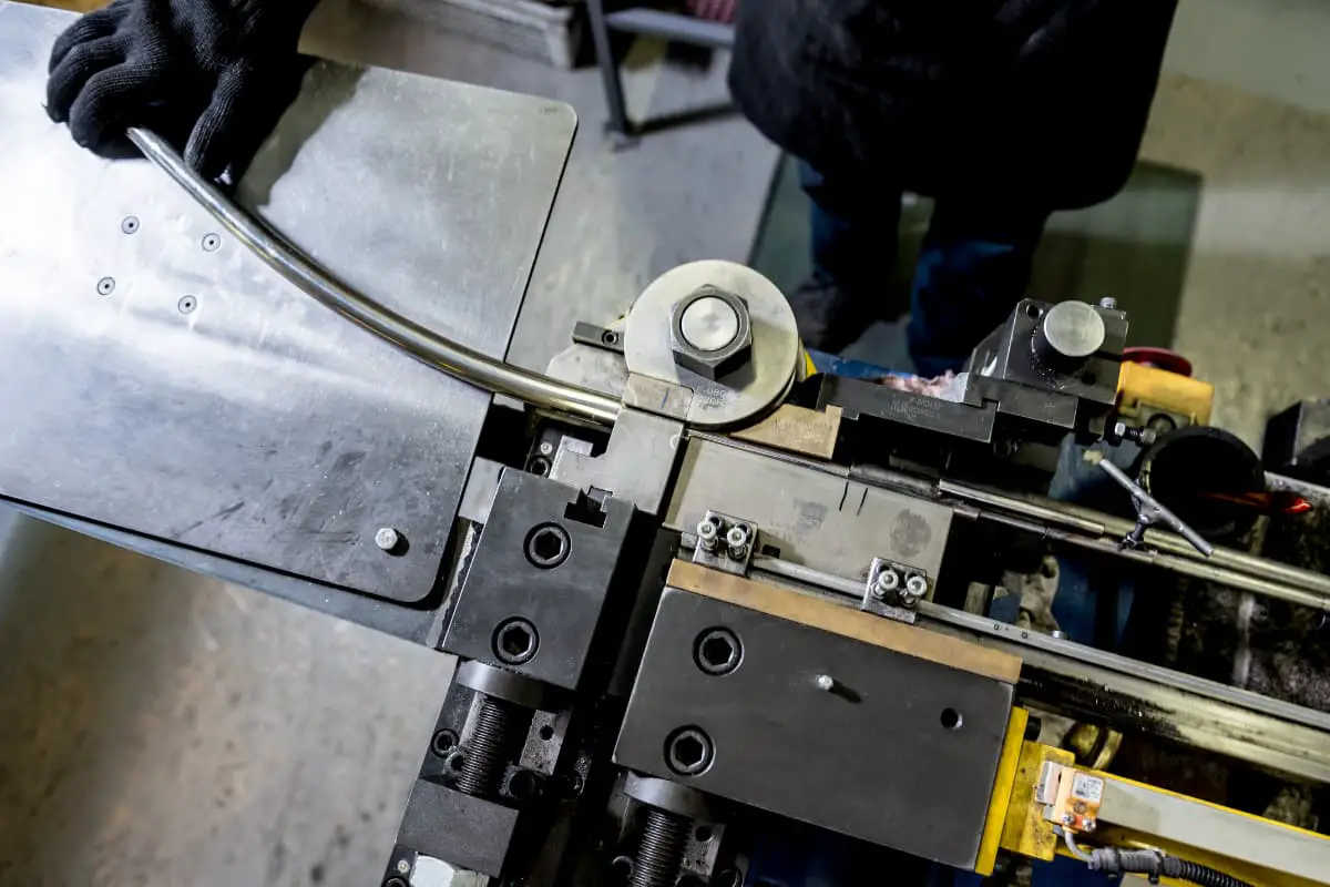
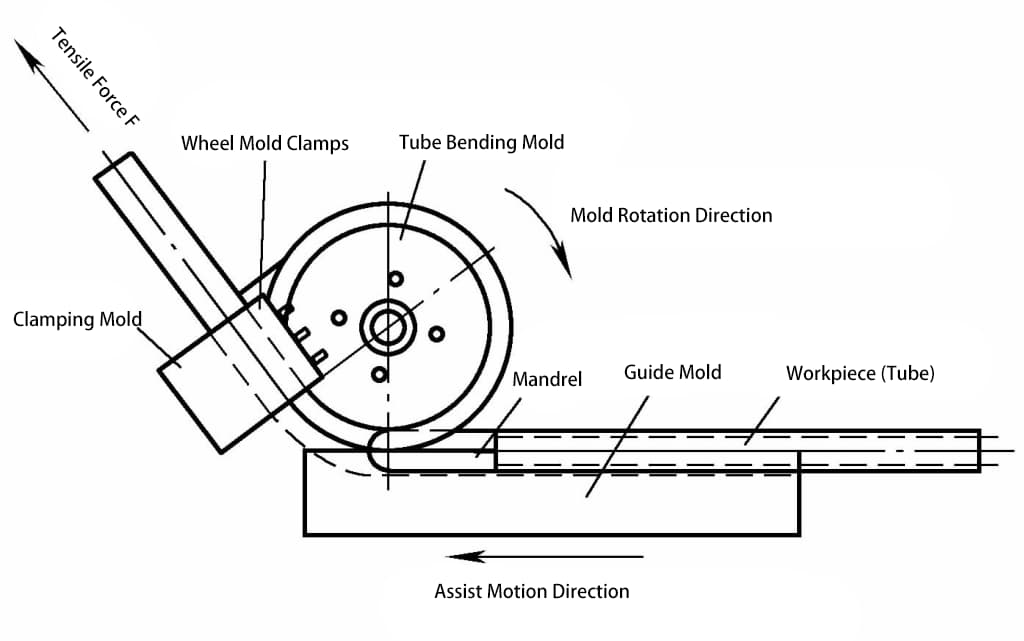
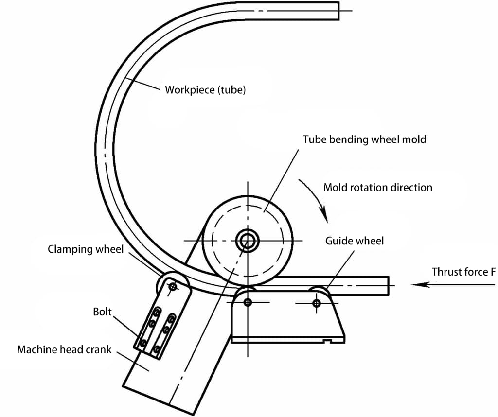
Taking the CNC numerical control pipe bending process of Yituo Company as an example, the bending equipment used is a CNC numerical control pipe bender, and the pipe bending process used for numerical control pipe bending is cold bending pipe bending, which according to the forming principle of the numerical control pipe bender is divided into pull bending and push bending.
Pull bending forming principle: Under the action of the pulling force F holding the pipe fitting at the front end of the wheel mold, the pipe fitting rotates with a certain radius of the wheel mold and wraps the pipe around the mold to bend and form, as shown in Figure 4-16. Pull bending is similar to the industry’s bending around.
Push bending forming principle: Under the action of the pushing force F applied behind the pipe fitting, the pipe is formed and the curvature radius of the arc is determined by using the positioning angle of the machine head bending arm, as shown in Figure 4-17. Push bending is similar to the industry’s roll bending.
The basis for selecting the pipe forming method is as follows:
Draw bending: Draw bending forming is used under the condition of 2.5≤R s ≤6.
Push bending: Push bending forming is used under the condition of R s ≥6.
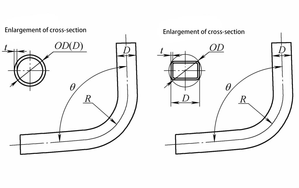
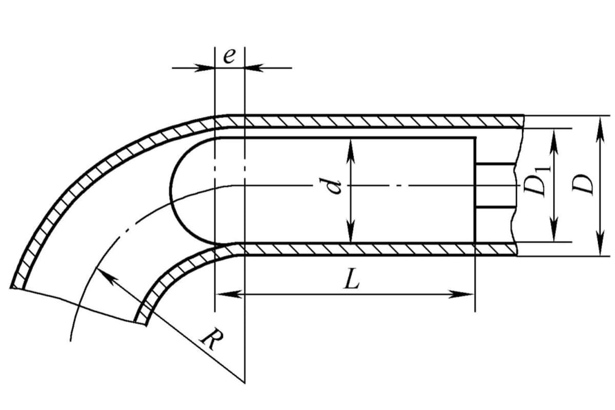
Note: R s =R/D where R is the neutral layer radius of a bent pipe fitting; D is the diameter of the pipe in the bending direction (see Figure 4-18).
