Exploring Different Types of Mechanical Seals
What keeps pumps, compressors, and other machinery running smoothly and without leaks? The answer lies in the different types of…
What if you could join metals without melting them? Friction welding makes this possible by using heat generated from mechanical friction. This article explores various types of friction welding, such as rotary, inertia, and friction stir welding. It details how each method works, their unique advantages, and practical applications. By understanding these techniques, you’ll gain insights into advanced welding processes that enhance efficiency and strength in manufacturing. Dive in to discover how friction welding is revolutionizing the way we bond materials.
Friction welding is classified according to the form of relative motion, divided into rotary friction welding and friction stir welding.
The characteristic of rotary friction welding is that at least one workpiece (or ring) rotates around an axis perpendicular to the joint surface during the welding process. This type of friction welding is mainly used for welding circular cross-section workpieces (and can also be used for non-circular cross-section workpieces through phase control), and is currently the most widely used and varied form of friction welding.
Based on the rotational characteristics of the workpieces, rotary friction welding can be further divided into continuous drive friction welding, inertia friction welding, and hybrid rotary friction welding, etc.
1) Continuous Drive Friction Welding.
Continuous drive friction welding is the most commonly used type of friction welding. Its characteristic is that the rotating workpiece is directly connected to the spindle chuck, and the non-rotating workpiece is mounted on the hydraulic tailstock backing plate chuck. During welding, the tailstock backing plate is advanced, bringing the workpieces into contact under constant or increasing pressure.
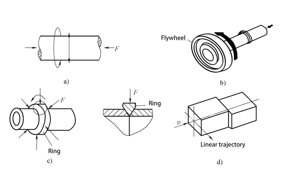
When the rotating spindle heats the workpiece to the welding temperature through friction, the spindle stops rotating, and forging begins, completing the welding. In continuous drive friction welding, the workpiece continues to rotate under the action of the rotating device and continuous drive until just before the start of forging, as shown in figure 5-166a.
2) Inertia Friction Welding.
The principle of inertia friction welding is similar to continuous drive friction welding, except that the rotating weldment is not directly connected to the spindle, but is connected to the spindle via a flywheel.
At the start of welding, the flywheel and the rotating end of the weldment are first accelerated to a certain speed, then the flywheel is disengaged from the main motor, and at the same time, the moving end of the weldment moves forward. Once the weldments touch, friction heating begins. During the friction heating process, the flywheel is braked by the friction torque, gradually reducing its speed until it reaches zero, at which point the welding process ends.
Inertia friction welding utilizes the inertial energy storage method (such as a flywheel) to accumulate energy for joint heating, as shown in Figure 5-166b, where the kinetic energy of the freely rotating flywheel provides all the heat required for the weldment.
3) Hybrid Rotary Friction Welding.
Hybrid rotary friction welding is a combination of continuous drive friction welding and inertia friction welding. This type of welding machine is characterized by the ability to apply and not apply braking force after disconnecting the drive source.
Friction stir welding is a new solid-state joining technology invented in 1991, considered a significant scientific and technological achievement from basic research to practical application. Initially used for welding aluminum alloys, friction stir welding has been widely applied in the welding of non-ferrous metals such as magnesium and titanium alloys, as well as dissimilar materials.
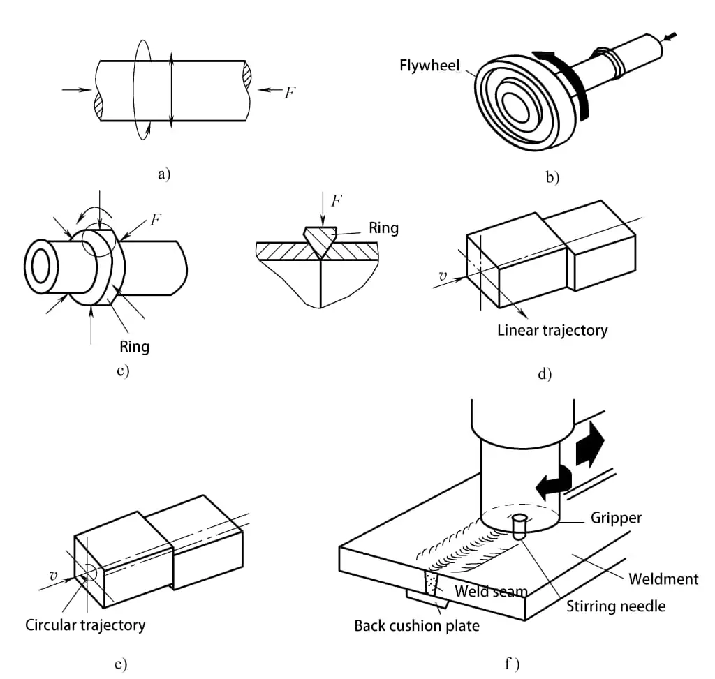
Figure 5-166f is a schematic diagram of friction stir welding. During friction stir welding, the workpiece is fixed, and the welding is mainly completed by the stirring head. The stirring head consists of a stirring pin, a holder, and a cylinder.
At the start of welding, the stirring head rotates at high speed, and the stirring pin quickly drills into the seam of the weld plate. The metal in contact with the stirring pin generates heat due to friction, forming a very thin thermoplastic layer.
When the stirring needle penetrates below the surface of the weldment, some metal is extruded from the surface. Due to the sealing effect of the front shoulder and the back pad, on one hand, the shoulder rubs against the surface of the welded plate, generating auxiliary heat; on the other hand, the thermoplastic metal continuously formed in front of the stirring head is transferred to the back of the stirring head, filling the cavity behind.
Throughout the welding process, the formation and filling of cavities are continuous, and the metal in the weld zone undergoes processes such as extrusion, frictional heating, plastic deformation, transfer, diffusion, and recrystallization.
The characteristic of track-type friction welding is that every point on the joint surface of the weldment moves in the same trajectory relative to a point on the joint surface of another weldment. The trajectory of movement can be linear or non-linear.
During the welding process, one side of the weldment moves relative to the surface of the other side, which is clamped, under the action of a track-type mechanism, and axial pressure is applied. As the friction movement progresses, the friction surface is cleaned and generates friction heat, the metal on the friction surface gradually reaches a viscoplastic state and deforms, then the movement stops and forging force is applied to complete the welding.
Track-type friction welding breaks the limitation of traditional rotary friction welding that can only weld cylindrical section weldments, and this type of friction welding can weld square, circular, and polygonal section weldments.
Based on different motion trajectories, track-type friction welding is divided into linear friction welding and trajectory friction welding, as shown in Figures 5-166d and e.
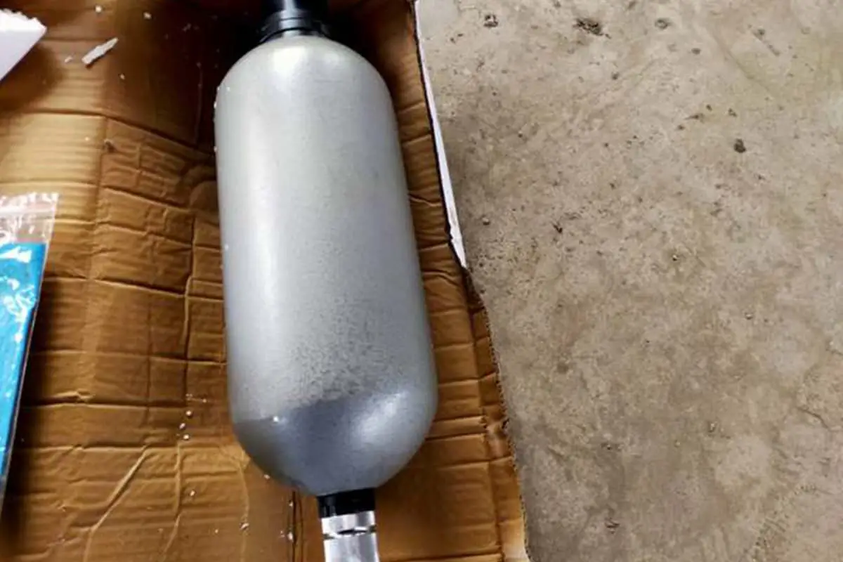
Embedded friction welding utilizes the principle of friction welding to embed a relatively harder material into a softer material.
Figure 5-167 shows the working principle of embedded friction welding. During operation, the frictional heat generated by the relative motion between the two weldments causes local plastic deformation in the soft material, and the high-temperature plastic material flows into the recesses of the pre-processed hard material. The restraining shoulder forces the high-temperature plastic material to tightly wrap around the hard material’s joint. When rotation stops and the weldments cool down, a reliable joint is formed, and the two sides of the weldments are mechanically interlocked.
Embedded friction welding is currently mainly used in very important material connections in industries such as power, vacuum, and cryogenic applications, such as aluminum-copper, aluminum-steel, and steel-steel. Embedded friction welding can also be used to manufacture engine valve seats, connection ends, pressure caps, and tube sheet transition joints, and can also be used to connect thermosetting materials and thermoplastic materials.
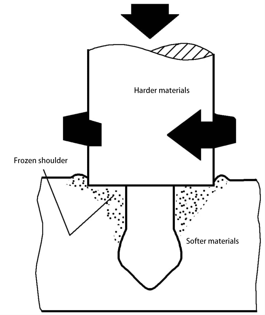
Figure 5-168 shows the working principle of third-body friction welding. A third material with a low melting point generates heat and plastic deformation through friction in the gap between the connected parts under the torque of axial pressure. The relative frictional movement can produce sufficient cleaning effect, without the need for flux and controllable protective atmosphere. After cooling, the third-body material solidifies, thus locking the two parts together to form a reliable joint.
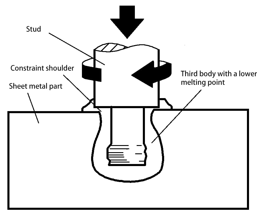
The third-body friction welding method is mainly used for materials that are difficult to weld, such as ceramic-ceramic, metal-ceramic, thermoset-thermoplastic composites, etc., and can be used to form high-strength joints.
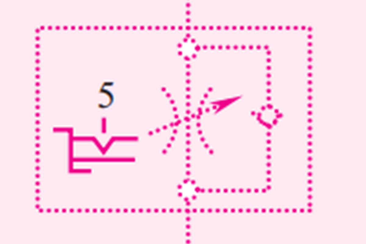
Phase-controlled friction welding involves phase control of the weldments after welding during the friction heating process, through mechanical synchronous pin fitting or synchronous drive systems, to align the back edges of the weldments, correct the direction, or meet phase requirements. It is used for welding parts with specific positional requirements such as hexagonal steel, octagonal steel, and automotive control racks.
The aforementioned rotary friction welding involves axial pressure during the welding process, while radial friction welding applies radial pressure. Radial friction welding involves beveling the ends of the two tubes to be welded, inserting a mandrel inside, aligning and clamping them together, and then placing a solid ring with a composition similar to that of the tubes into the joint bevel. This ring has an internal conical surface, and before welding, the internal conical surface should first contact the bottom of the bevel.
During welding, the workpiece remains stationary, the ring rotates at high speed and applies radial friction pressure to both ends of the tubes. After the friction heating is completed, the rotation of the ring stops, and top forging pressure is applied to the ring to weld it firmly to both ends of the tubes, as shown in Figure 5-166c.
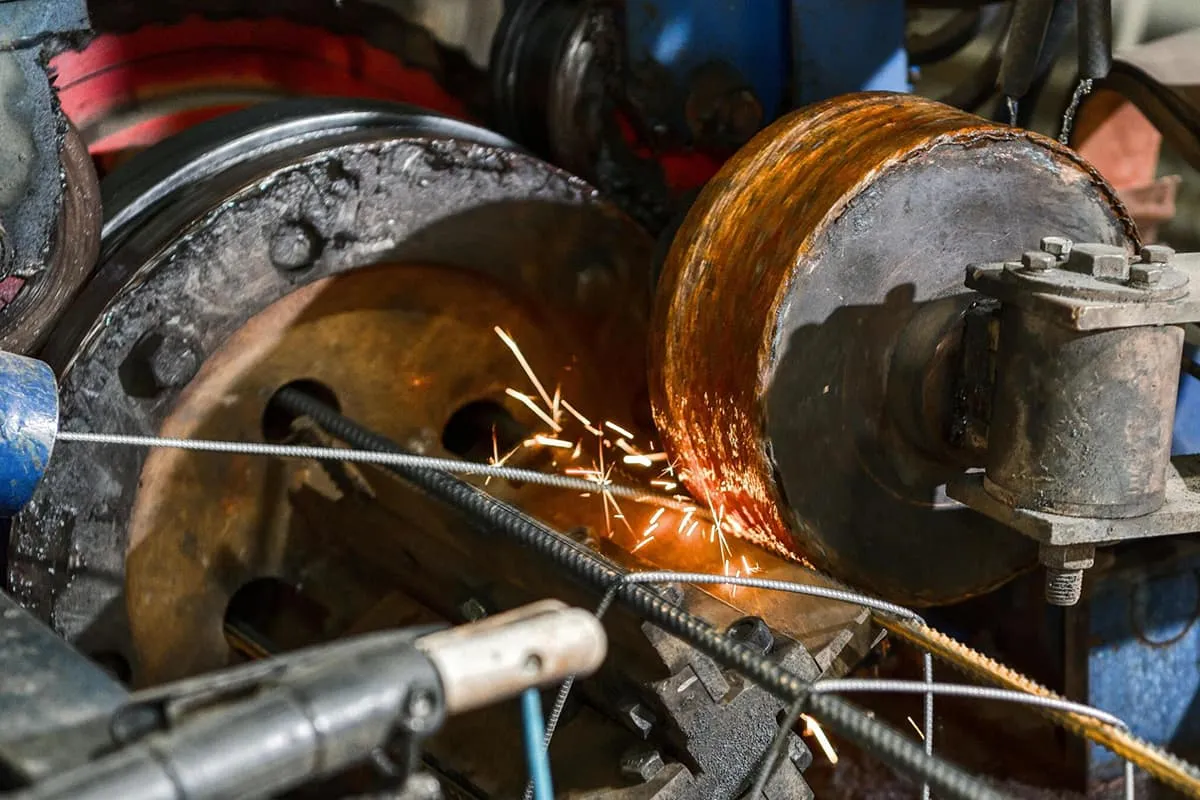
The principle of friction surfacing is shown in Figure 5-169. The surfacing metal rod rotates relative to the workpiece n, and the parent material (base material) also rotates at speed n2. Under the action of pressure P, the rod and the base material generate heat due to friction. Since the base material has a large volume and cools quickly, the surfacing metal transitions to the base material forming a surfacing weld.
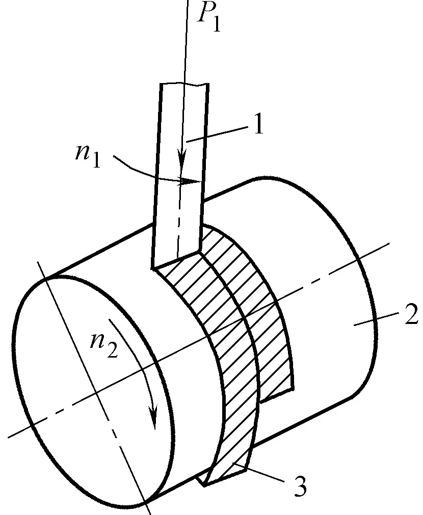
1—Surfacing metal rod 2—Surfacing workpiece 3—Surfacing weld
Friction surfacing is suitable for joining dissimilar materials, especially since the surfacing weld metal has high lattice distortion, fine grains, and good toughness, making it suitable for surface surfacing.
Superplastic friction welding is classified according to welding process characteristics. It involves controlling measures to maintain the weld zone in a superplastic state during the welding process. The advantage is that it can avoid the formation of hard and brittle intermetallic compounds at high temperatures and maintain the heat treatment state of the welded material. It is suitable for joining dissimilar difficult-to-weld metals and can also be used for effective connection of special metals.