I. Classification of pipe bending forming equipment
1. Pipe bender
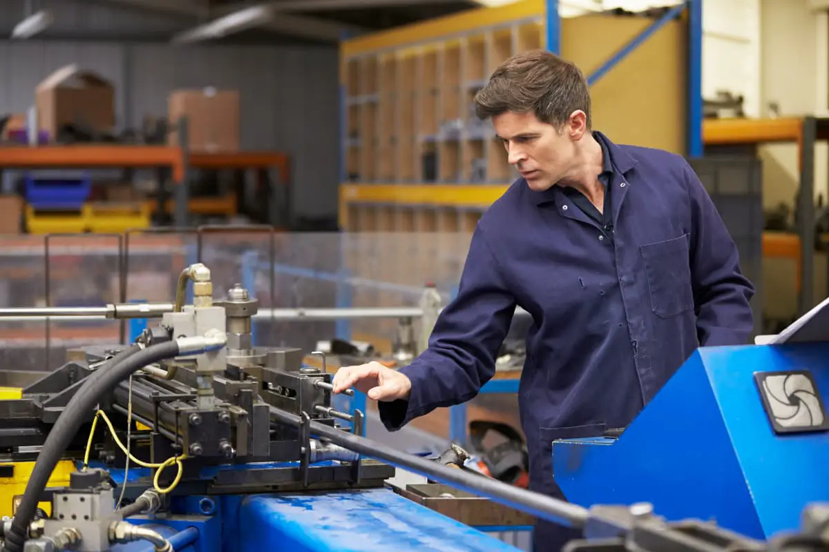
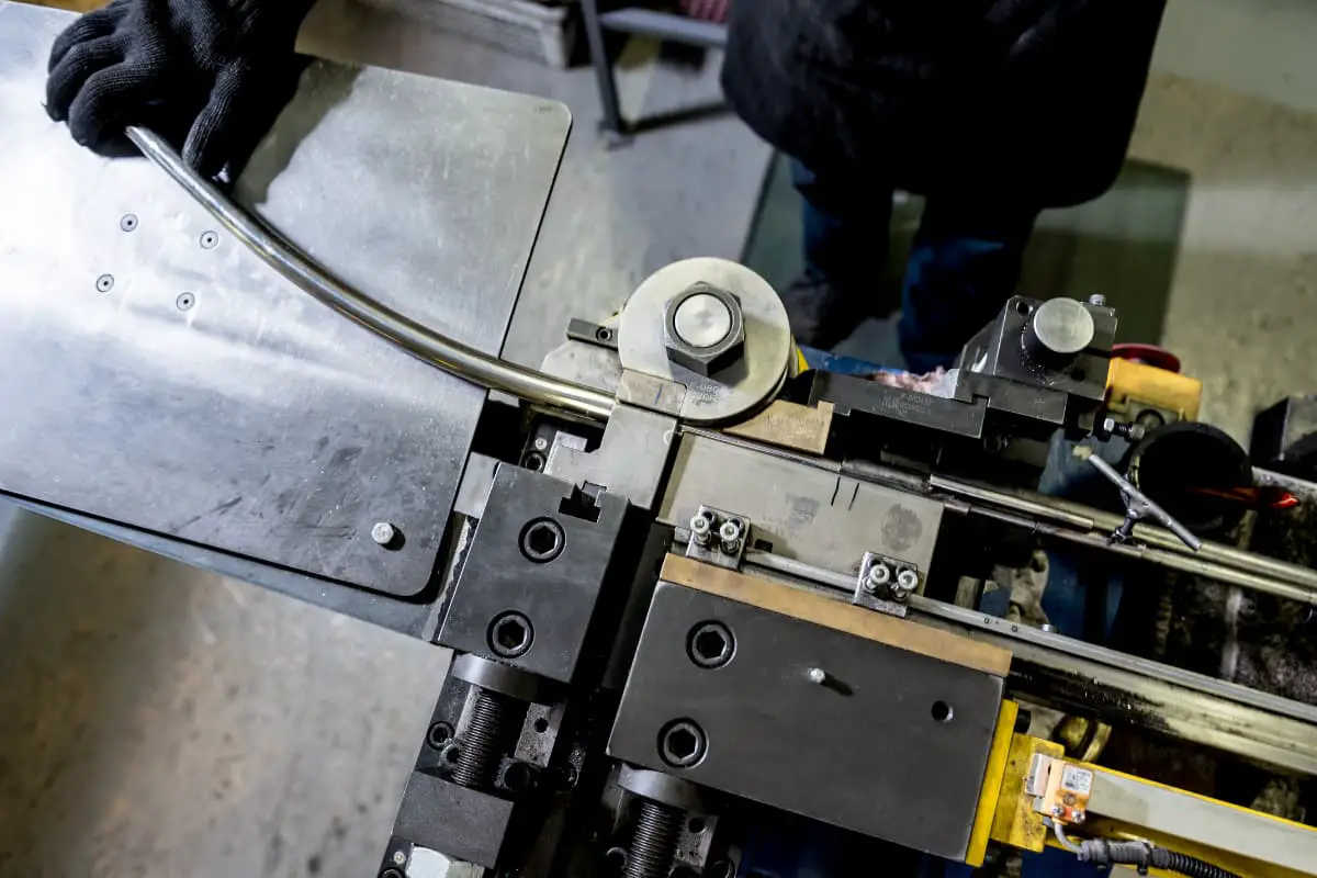
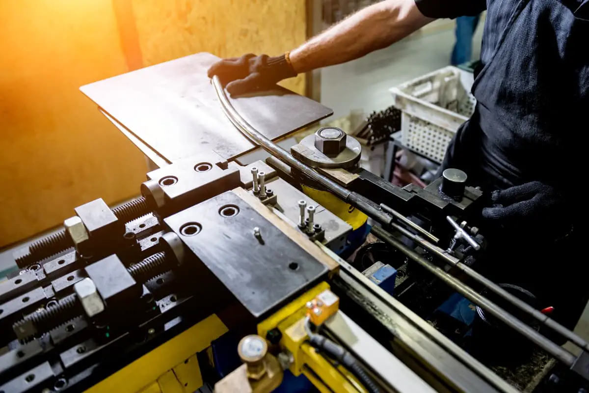
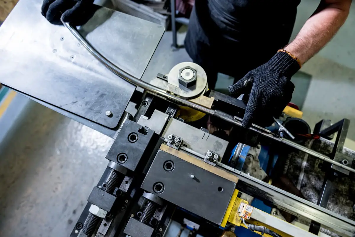
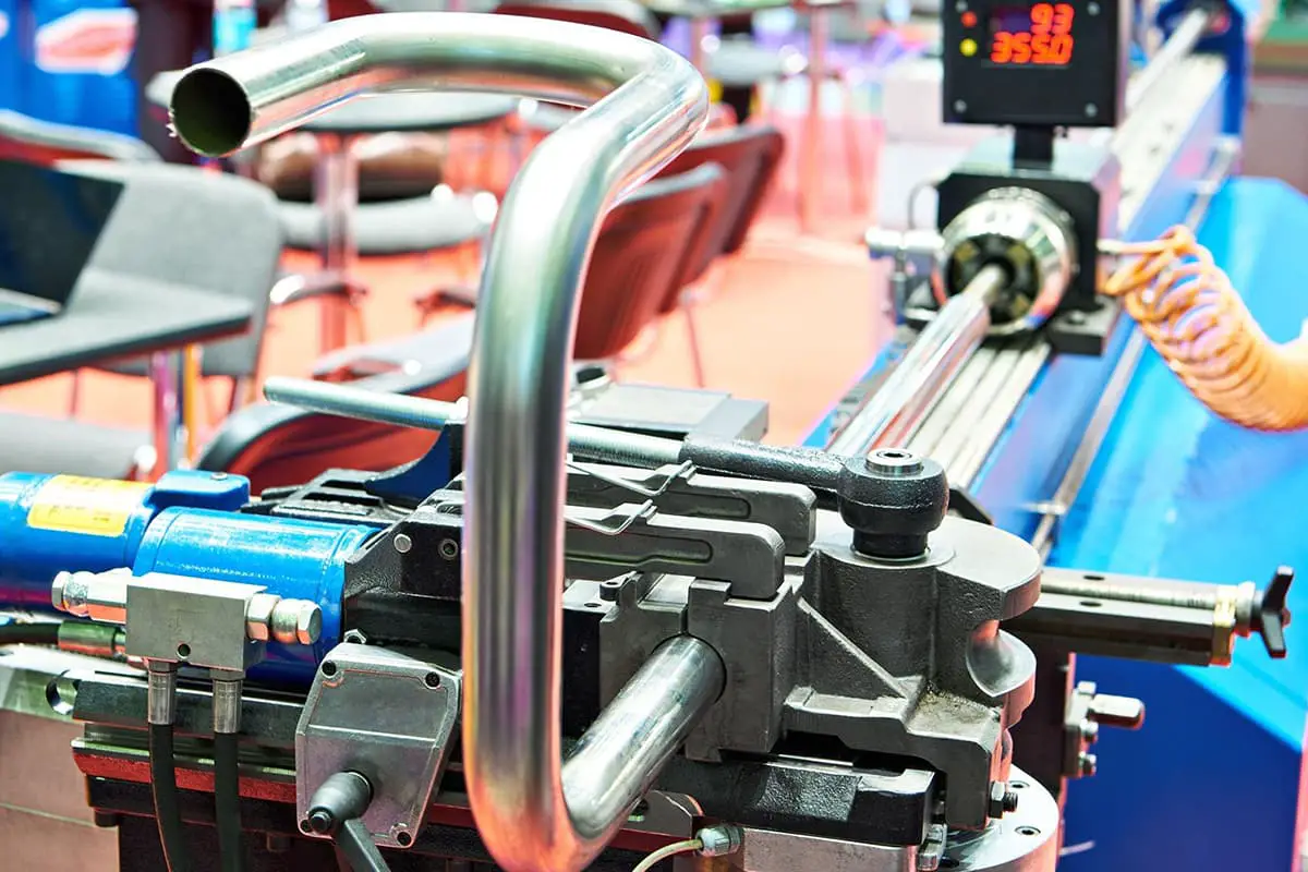
The pipe bender is the main equipment for pipe processing. There are many structural forms of pipe benders, which can be divided into cold pipe benders and hot pipe benders according to whether heating is applied during bending, into mechanical transmission and hydraulic transmission according to the transmission method, and into manual control, semi-automatic, automatic, and CNC according to the control method. Mechanical transmission pipe benders have a simple structure, are convenient to manufacture, and have greater versatility.
Hydraulic pipe benders have smooth and reliable transmission, low noise, compact structure, and can bend pipes of different diameters. Semi-automatic controlled pipe benders generally only automatically control the bending angle and are mainly used for medium and small batch production. Automatic controlled pipe benders can automatically control the entire process of pipe feeding, bending, and space turning angle bending. This type of pipe bender generally uses hydraulic transmission and is suitable for mass production and occasions with varying pipe sizes.
CNC pipe benders can automatically control the bending process according to the program and dimensions specified in the part drawing by inputting data. They are suitable for mass production, especially in occasions where the pipe size parameters vary frequently. This section briefly introduces the basic structure and main technical performance of commonly used cold and hot pipe benders in production.
(1) Cold pipe bender
1) Manual pipe bender.
The commonly used manual pipe bender, as shown in Figure 4-39, can bend pipes with diameters of 15, 20, 25. The manual pipe bender consists of a steel jacket 1, fixed guide wheel 3, movable guide wheel 2, and clamping ring 4, and is fixed to the frame with bolts.
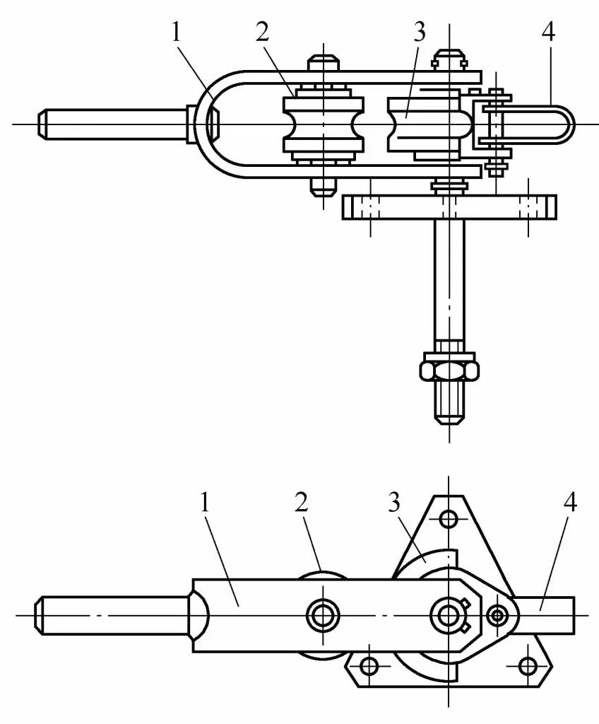
1—Steel jacket
2—Moving pulley
3—Fixed pulley
4—Clamping ring
Before bending the tube, first place the tube blank between the two pulleys, and insert the end of the tube into the clamping ring of the fixed pulley. During bending, rotate the steel jacket and drive the moving pulley to rotate around the fixed pulley, thus completing the bending process. The maximum bending angle of this manual bending machine can reach 180°, and its technical performance is shown in Table 4-10.
Table 4-10 Technical performance of manual bending machine
| Technical Indicators | Data | ||
| Bent pipe diameter/mm | 15 | 20 | 25 |
| Bending radius/mm | 50 | 63 | 85 |
| Dimensions/mm | 500 ×152 ×292 | 640×162 x292 | 722 ×230 ×271 |
| Weight/N | 110 | 140 | 170 |
2) Motorized bending machine.
The commonly used motorized (driven by worm gear and worm) bending machine, as shown in Figure 4-40, can bend tubes with diameters from Φ15 to Φ32mm. The motorized bending machine consists of a frame 1, a worm gear reducer 2, an electric motor 4, and four sets of pulleys 3, and its working principle is the same as that of the manual bending machine.
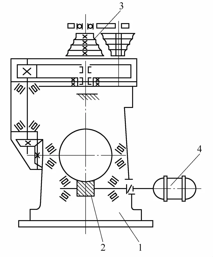
1—Frame
2—Worm gear reducer
3—Four guide wheels
4—Electric motor
When bending the pipe, first load the pipe blank into the guide wheel pair of the corresponding diameter and fix it with a clamp ring. Then start the electric motor to rotate the movable guide wheel around the fixed guide wheel to complete the bending work. The technical performance of this pipe bender is shown in Table 4-11.
Table 4-11 Technical performance of the motorized pipe bender
| Technical Indicators | Data | |||
| Bent pipe diameter/mm | 15 | 20 | 25 | 32 |
| Bending radius/mm | 49 | 63 | 87 | 114 |
| Maximum bending angle/(°) | 180 | |||
| Electric motor power/kW | 2.8 | |||
| Dimensions/mm | 650 ×975 ×1341 | |||
| Weight/N | 4900 | |||
3) Mandrel pipe bender
The mandrel pipe bender, as shown in Figure 4-41, can bend pipes with diameters from Φ32 to Φ159mm. When bending pipes of different diameters, guide wheels, pressure blocks, and mandrels of different diameters can be used.
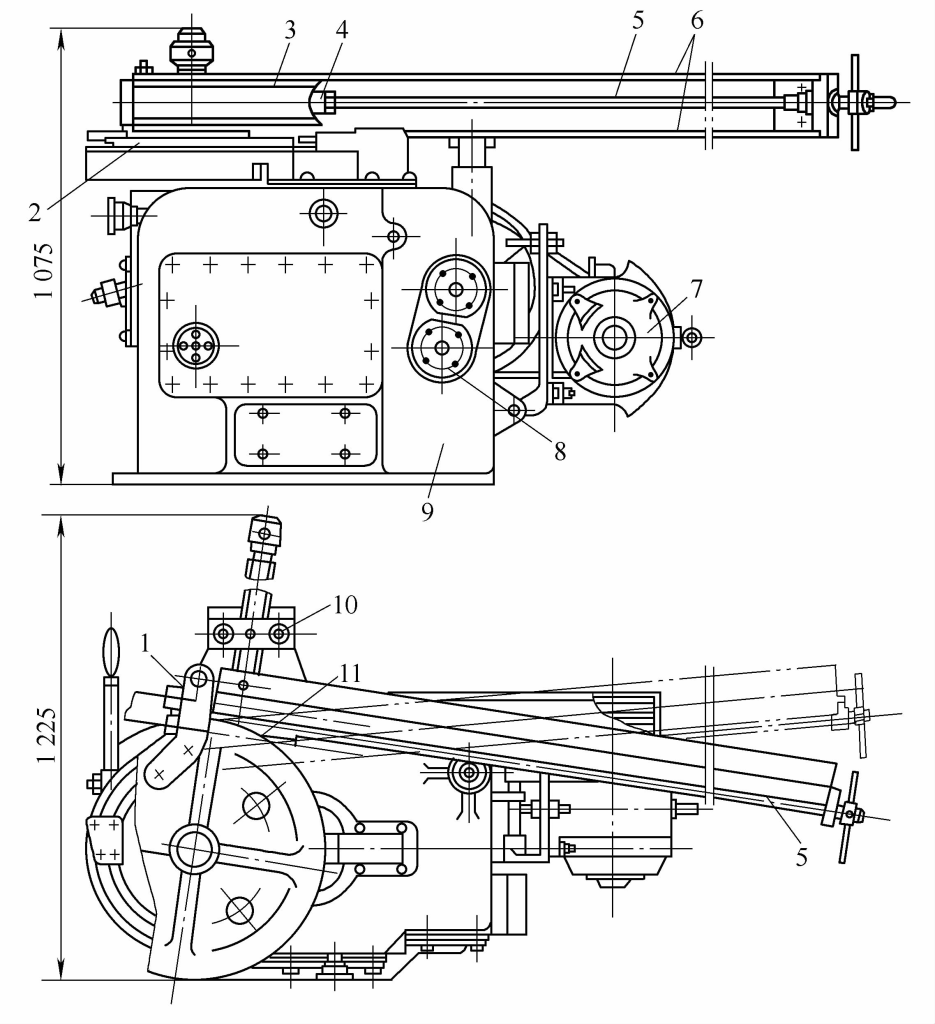
1—Eccentric clamp
2—Rotating worktable
3—Bending pulley
4—Mandrel
5—Pull rod
6—Support rod
7—Electric motor
8—Gear pair
9—Frame
10—Top frame
11—Press block
The mandrel bending machine consists of a frame 9 (with a reducer inside the frame), a rotating worktable 2, a bending pulley 3, a support rod 6 for the press block 11, a top frame 10, a mandrel 4, an eccentric collar 1, and an electric motor 7, etc. The bending machine has a handle that can control the clutch of the machine tool reducer, as well as the advance and retreat of the top frame and press block, to adjust the clamping degree of the pipe blank. The bending speed can be adjusted by changing the gear pair.
When bending pipes, first insert the mandrel into the pipe blank, and fasten the pipe blank to the bending guide wheel with an eccentric clamp. As the rotary table rotates, the pipe blank is gradually bent into shape. The mandrel remains stationary throughout the bending process, serving to support the pipe wall from the inside to prevent the bent part from becoming oval. The technical performance of the mandrel pipe bender is shown in Table 4-12.
Table 4-12 Technical performance of the mandrel pipe bender
| Technical Indicators | Data | |||
| Bent pipe diameter/mm | 32~89 | 38 ~108 | 38 ~159 | |
| Maximum wall thickness of bent pipe/mm | 5 | 8 | 8 | |
| Bending radius/mm | 85~350 | 75 ~800 | 75 ~1000 | |
| Maximum bending angle/(°) | When the bending radius is ≤ 400mm | 180 | 180 | 180 |
| When the bending radius is >400mm | — | 90 | 90 | |
| Bending guide wheel rotation speed / (r·min -1 ) | 0.6 | 0.43 | 0.43 | |
| Number of matching guide wheels | 6 | 9 | 11 | |
| Electric motor power/kW | 4.5 | 7 | 2×7 | |
| Weight/N | 16740 | 27340 | 40000 | |
The large mandrel pipe bender, as shown in Figure 4-42, can bend pipes with diameters from Φ108 to Φ219. The machine is equipped with a sectorial pull plate 2, a complete set of interchangeable bending sector wheels 1, pipe blank holder 3, mandrel 4, worktable 5, support 6, mandrel support rod 7, and an electric winch 8.
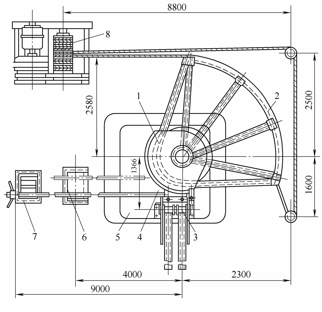
1—Bending sector wheel
2—Sectorial pull plate
3—Pipe blank holder
4—Mandrel
5—Worktable
6—Bracket
7—Core Rod Support
8—Electric Winch
The electric winch for the pipe bender is driven, pulling the sector rod through the steel wire rope. The winch drum is divided into two parts, one for winding and one for releasing. When the drum rotates in reverse, the sector rod returns to its original position.
When bending pipes of different diameters, corresponding diameter bending sector wheels, billet holders, and mandrels can be replaced.
The technical performance of this large pipe bender is shown in Table 4-13.
Table 4-13 Technical Performance of Large Pipe Bender
| Technical Indicators | Data |
| Bent pipe diameter/mm | 108,114,133,159,168,219 |
| Maximum wall thickness of bent pipe/mm | 8 |
| Bending radius/mm | 4D (D is the diameter of curvature) |
| Maximum bending angle/(°) | 90 |
| Bending speed/(m·min-“) | 8 ~10 |
| Traction force/kN of electric winch during pipe bending | 50 |
| Dimensions/m | 11.8 x4.65 x1.3 |
4) Hydraulic Pipe Bender
The commonly used hydraulic pipe bender is shown in Figure 4-43, and its technical performance is shown in Table 4-14.
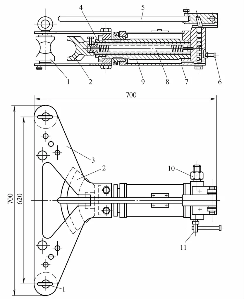
1—Top roller
2—Pipe bending die
3—Jacket
4—Reset spring
5—Handle
6—Oil nozzle
7—Oil tank
8—Piston rod
9—Hydraulic Cylinder
10—Oil Inlet Nozzle
11—Needle Valve
Table 4-14 Technical Performance of Hydraulic Pipe Bender
| Technical Indicators | Data | ||
| Bent pipe diameter/mm | 15,20,25 | 25,32,40,50 | 76,89,114,127 |
| Maximum bending angle/(°) | 90 | 90 | 90 |
| Maximum piston rod stroke/mm | 300 | 310 | 530 |
| Maximum Pressure/MPa | — | 300 | 300 |
| Hydraulic Press Performance | Manual piston pump | Manual piston pump or motorized pump | Electric piston pump |
| Maximum pressure of the hand pump /N | 200 | 230 | — |
| Electric motor power/kW | — | — | 2.8 |
| Pipe bending mold rotation speed during bending / (mm·s -1 ) | — | — | 4.5 |
| Dimensions/mm | — | 700 ×700 ×220 | 1500 x1400 x700 |
| Weight/N | 175 | 460 | 6320 |
Note: The wall thickness of the pipe is 3 to 7mm.
(2) Medium Frequency Induction Heating Pipe Bender
The medium frequency induction heating pipe bender is a commonly used thermal bending equipment, capable of performing the bending process of heating, bending, and cooling continuously. This type of pipe bender consists of mechanical and electrical parts, where the mechanical part includes the clamping and force-applying parts for bending, and the electrical part includes the motor and the medium frequency generator. Depending on the method of applying bending torque, pipe benders are divided into push bending and pull bending types.
1) Push Bending Type Medium Frequency Induction Heating Pipe Bender.
The working principle of the push bending type medium frequency induction heating pipe bender is shown in Figure 4-44. It completes the bending process by applying axial thrust F to the pipe blank, heating, bending, and spraying water for cooling. The technical performance of this pipe bender is shown in Table 4-15.
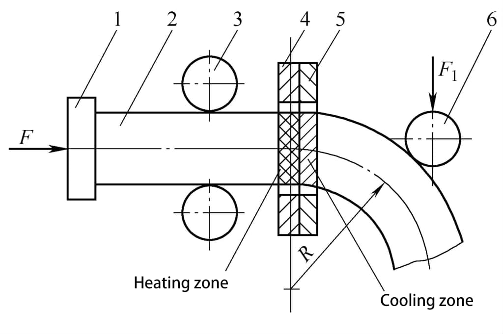
1—Thrust baffle
2—Pipe blank
3—Guide wheel
4—Medium frequency induction coil
5—Cooler
6—Top wheel
Table 4-15 Technical Performance of Medium Frequency Induction Heating Pipe Bending Machine
| Technical Specifications | Data | |
| Pipe Bending Diameter/mm | 952~99 | |
| Pipe Wall Thickness /mm | <10 | |
| Minimum Bending Radius /mm | 1.5D (where D is the diameter of the bend) | |
| Feed speed of the mechanism / (mm·s -1 ) | Longitudinal | 0.3~3 |
| Lateral | 0.2~2 | |
| Power of longitudinal and transverse transmission motors/kW | 4.5 | |
| Medium Frequency Induction Heating Device | Power/kW | 100 |
| Frequency/Hz | 2500 | |
| Dimensions/m | 5. 2 x1. 62 x1. 05 | |
| Weight/kN | 50 | |
2) Medium frequency induction electric heating pipe bending machine.
The structure principle of the medium frequency induction electric heating pipe bending machine is shown in Figure 4-45, mainly used for bending thick-walled (less than 30mm) pipe fittings. This type of pipe bender is simpler than the above-mentioned push bending pipe bender because it does not need to set up longitudinal and transverse top pipe mechanisms, and the bending work can be completed by driving the fan-shaped disc 5 with an electric winch 10.
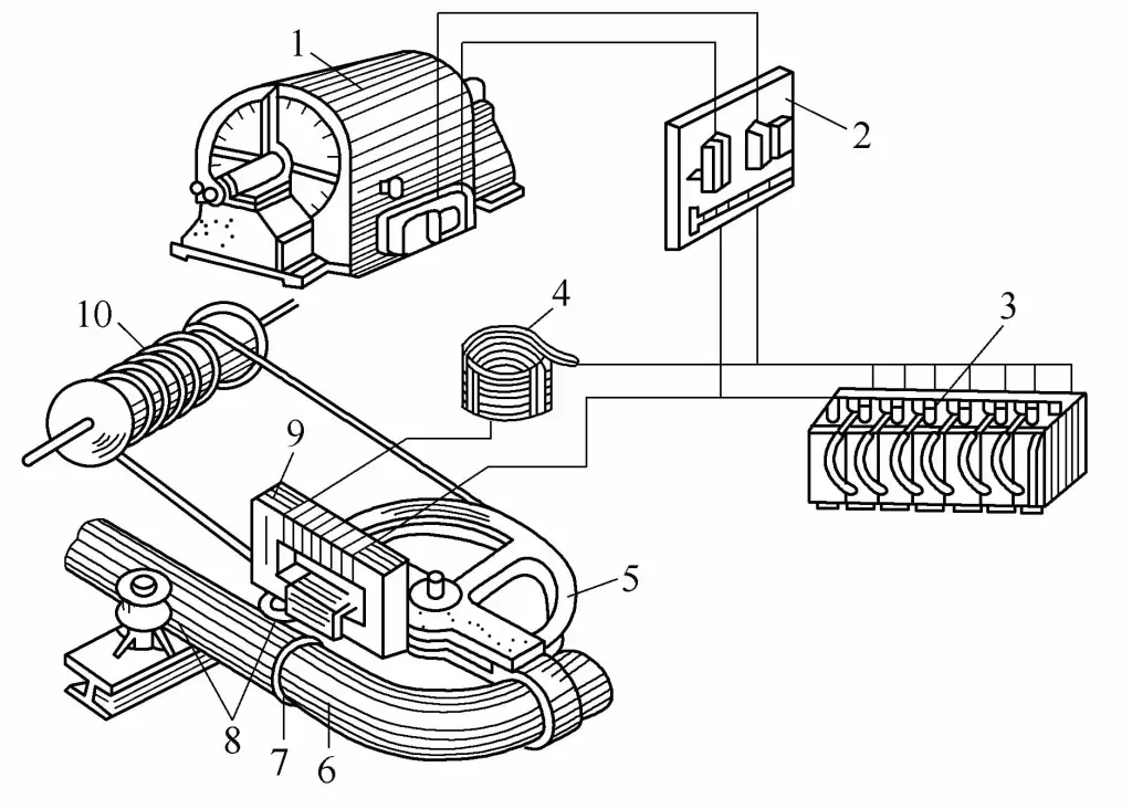
1—Medium frequency generator
2—Switchboard
3—Battery pack
4—Reactor
5—Fan-shaped disc
6—Pipe blank
7—Induction coil
8—Guide wheel
9—Transformer
10—Electric winch
When bending pipes with a medium frequency induction heating bender, the gap between the induction coil and the inner side of the bend should be smaller, and larger on the outside, to ensure the heating effect on the inner wall of the pipe. The width of induction heating depends on the medium frequency power, the width of the induction coil, and the relative position of the induction coil to the billet, generally about 10~20mm.
The bending technical parameters of 20# steel pipe with medium frequency induction heating bender are shown in Table 4-16, for reference.
Table 4-16 Medium frequency bending technical parameters for 20# steel pipe
| (Outer diameter D/mm) x (Wall thickness t/mm) | Power consumption/kW | Bending speed / (mm·s -1 ) | Heating temperature/℃ |
| Φ83×14 | 60~70 | 1~1.2 | 900~950 |
| Φ102×16 | 70~75 | 0.9~1.1 | 900~950 |
| Φ102×22 | 70~75 | 0.8~1 | 900~950 |
| Φ127×19 | 70~75 | 0.8~1 | 900~950 |
| Φ127×28 | 75~80 | 0.6~0.7 | 950 ~1000 |
| Φ159×28 | 80~90 | 0.5~0.6 | 950~1000 |
| Φ180×28 | 90~100 | 0.4~0.5 | 1000~1050 |
Stainless steel pipes can be bent with a medium frequency induction heating bender. Special attention should be paid to the heating temperature to ensure it is not lower than 900℃. This is because stainless steel has a tendency to suffer from intergranular corrosion when heated for a long time within the temperature range of 500~850℃, hence stainless steel pipes can only be cold bent or hot bent at temperatures between 1100~1200℃. The bending technical parameters for bending stainless steel pipes with a medium frequency induction heating bender are shown in Table 4-17.
Table 4-17 Medium frequency bending technical parameters for stainless steel pipes
| (Outer diameter D/mm) x (Wall thickness t/mm) | Power consumption/kW | Bending speed / (mm·s -1 ) | Heating temperature/℃ |
| Φ89 x4.5 | 30~40 | 1.8~2 | 1100~1150 |
| Φ108 x5.5 | 30~40 | 1.2~1.4 | 1100~1150 |
| Φ133×6 | 40~50 | 1~1.2 | 1100~1150 |
| Φ159 x6 | 50~60 | 0.8~1 | 1100~1150 |
| Φ168×13 | 70~80 | 0.8~1 | 1130~1180 |
| Φ102×17 | 80~90 | 0.6~0.8 | 1130~1180 |
2. Roll bending machine
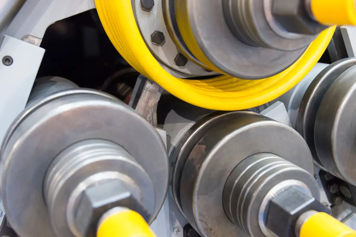
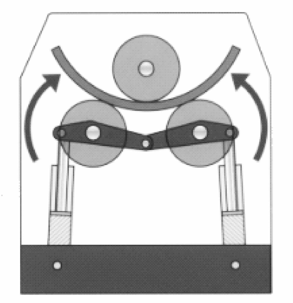
The working principle of the roll bending machine is shown in Figure 4-46. The pipe blank is placed between three rollers, and the pipe can be bent into pipe fittings with different curvatures by adjusting the relative positions of the three rollers. The roll bending machine is shown in Figure 4-47.
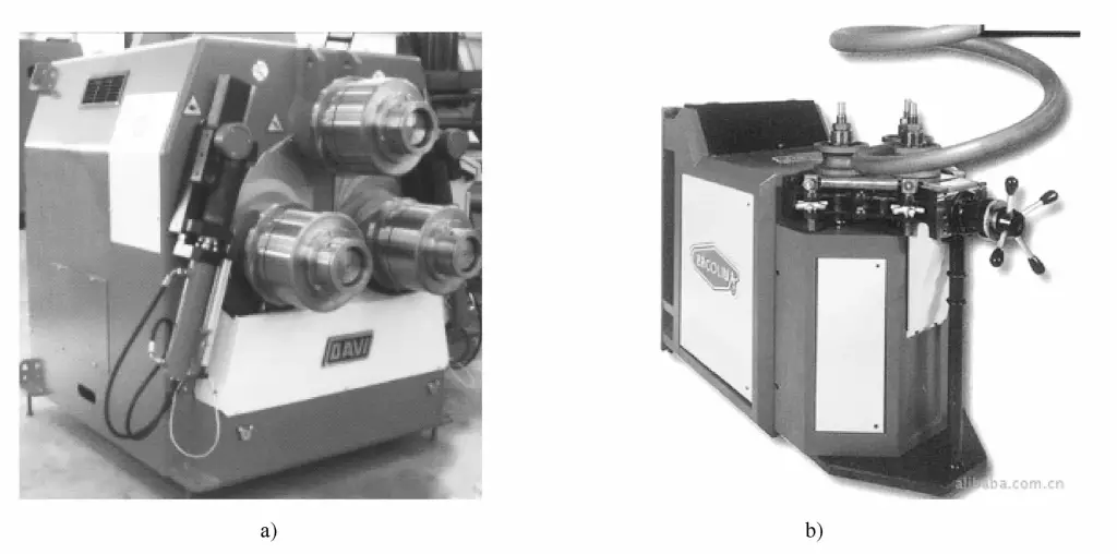
a) Horizontal roll bending machine
b) Vertical roll bending machine
The roll bending machine is mainly used for bending metal profiles or special-shaped materials such as iron, copper, aluminum, etc. It is widely used in furniture factories for bending circular arc furniture or in iron art engineering, metal doors and windows factories for circular arc iron doors and windows or aluminum alloy doors and windows, etc. Using CNC technology for pipe bending makes the operation of bending profiles more convenient and simple, and it has the advantages of high bending precision, and the bent profiles have less deformation, and no scratches on the surface.
The commonly used pipe bending machine is a three-axis CNC processing equipment. The roll bending machine can obtain large-radius finished products through repeated bending. General-purpose processing machines can adapt to the processing requirements of some shapes and materials. The fully hydraulic type of equipment is controlled by programmable eight programs, and each program can record infinitely many variations.
All manual control units are specially configured for dual-speed center wheels. The position of the center wheel is displayed digitally. The bending speed can reach up to 20ft/min (about 6.10m/min). All models of machines can work horizontally and vertically. The threaded drive shaft allows for precise fine-tuning, even when processing without any gaps.
The coaxial gear design reduces oil bath and ensures high power transmission efficiency. The drive shaft made of tempered alloy steel is equipped with tapered roller bearings. A low-voltage controller is used. The performance-improved hydraulic cylinder of the center roller is located inside the frame. The manual control panel includes a foot pedal controller. The adjustable roller system facilitates the correction of rotation situations. The tool storage compartment is integrated into the bottom of the machine.
The features of the bending machine are as follows:
1) It can be used for bending processing of large arcs and spiral pipes, usually with a bending radius greater than 6 times the diameter of the pipe.
2) Compact structure, high reliability, not easy to slip, improving the quality and feasibility of pipe fittings.
3) Smooth transmission, using a combination of three-roll molds, combined with adjustment and compression, can obtain circles, arcs, or spirals of different curvatures.
4) By changing the mold groove type, various metal profiles such as angle steel, flat steel, round tubes, and other special-shaped section profiles can be processed.
5) Bending large-radius profiles avoids the disadvantages of making extra-large bending molds and can complete work that single-head and double-head bending machines cannot.
3. Press
The press is mainly used for mold bending.
4. 3D Bending Machine
The 3D bending machine is mainly used for the plastic forming processing of car door frames, window frames, water channels, and other spatially curved parts. It is an automated equipment integrating electrical and hydraulic transmission. Figure 4-48 shows a 3D bending machine produced by a certain factory.
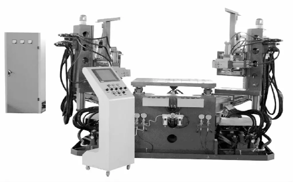
Working principle: This equipment mainly relies on hydraulic cylinders to drive various moving components to achieve the processing and forming work of the workpiece. The equipment is divided into 4 hydraulic systems, each with a pressure range of 0~150bar (adjustable), allowing to exceed the system pressure by 20%.
The lifting force of the left and right arms is controlled by two 30L/min hydraulic pumps respectively, using a proportional relief valve to control the lifting torque. The set pressure and actual pressure deviation is about 3%, with a repeatability stability coefficient of (20°C-40) 1% ⊙ ( ⊙ indicates an error of 1% at a temperature of 20°C and humidity of 40%). The bending hydraulic cylinders and clamping, rotating hydraulic cylinders on the left and right arms are controlled by two 80L/min hydraulic pumps.
The lifting of the Z-axis and the worktable are controlled by two hydraulic pumps of 52L/min and 30L/min respectively. It is possible to choose whether to turn on the hydraulic pump motor according to the arc requirements of the product being processed, which is beneficial for better energy saving.
In addition, the equipment is also equipped with 8 independent spare hydraulic interfaces and 4 independent spare pneumatic interfaces. All spare interfaces are connected to the hydraulic, electrical, and other systems of the whole machine, and can be set according to the requirements of different molds.
The equipment is quite simple in terms of mold changing. Generally, it takes about 2 hours for an operator to change a pair of ordinary intact molds (the time may change depending on the simplicity of the mold). The equipment can store information of multiple sets of molds, and after changing molds, it can promptly call out the production data of that set of molds for production, effectively reducing debugging time and shortening the processing cycle.
The technical parameters of the 3D bending machine are as follows:
1) The rotation angle of the worktable surface (-13°~+20°); the center rotation angle of the left and right swing arms is 90° each.
2) The distance between the left and right chucks L=0~3500mm is adjustable, and can perform a stretching movement of 600mm.
3) The center height of the chuck H=1280~1880mm, can move up and down 600mm along the linear slide rail.
4) The working table height H 1 =1200mm.
5) Hydraulic power 20MPa, motor power 15kW×3.
II. Classification of auxiliary equipment
The auxiliary equipment for pipe fitting forming includes pipe cutting equipment, commonly used are milling processing equipment, hole processing equipment, saw cutting processing equipment, plasma cutting processing equipment, and laser tube cutting equipment.
1. Milling processing equipment
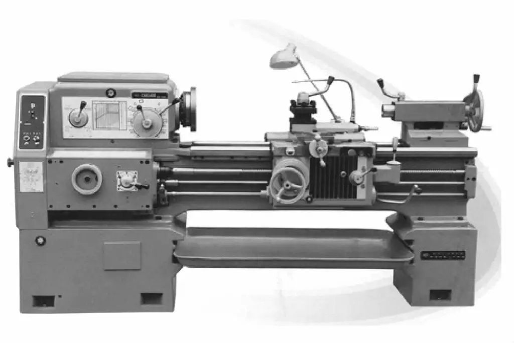
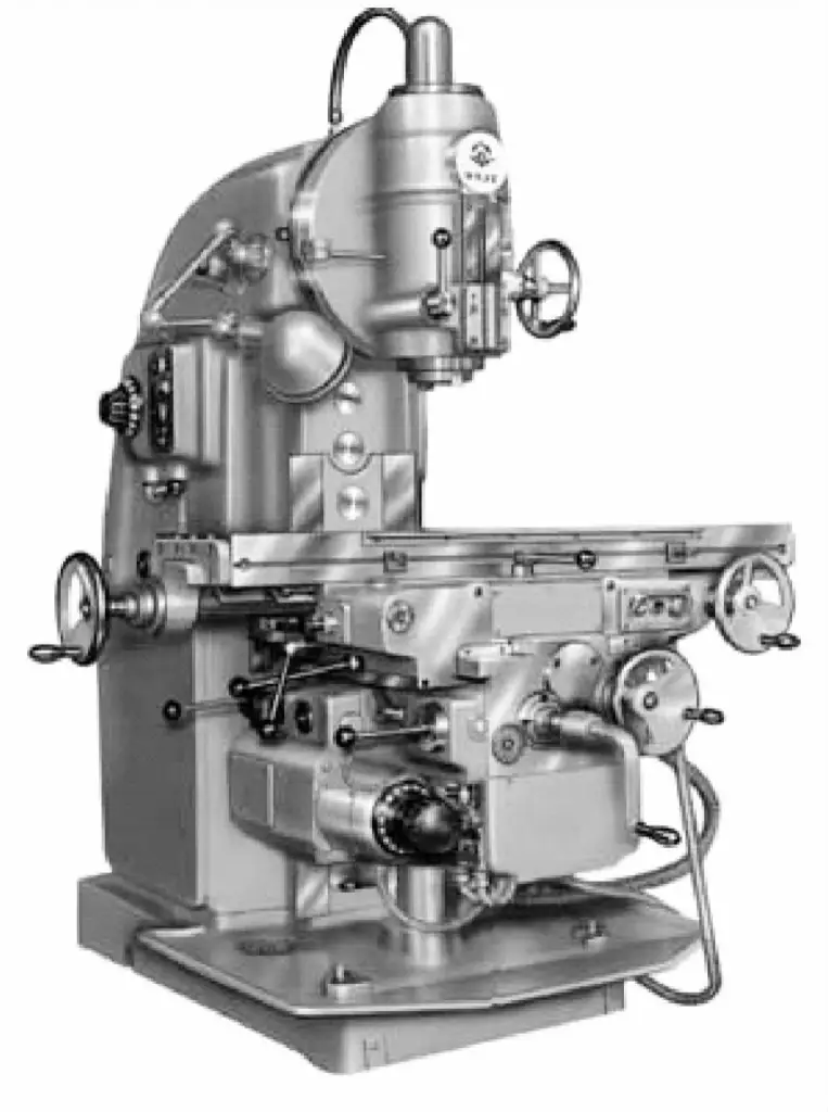
Milling processing is mainly used to process the relatively simple irregular forming surfaces between the overlaps of structural pipe fittings. The processing equipment used on-site mainly includes milling machines, lathes, and CNC milling machines, lathes, etc. The horizontal lathe is shown in Figure 4-49, and the vertical milling machine is shown in Figure 4-50.
2. Hole Machining Equipment
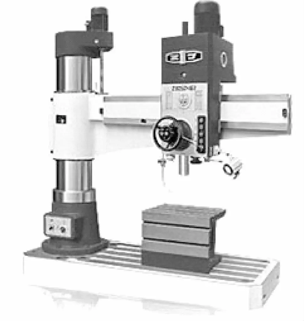
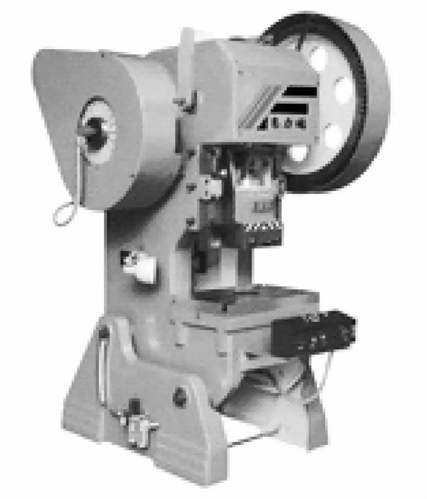
Hole machining equipment is mainly used for processing flow paint holes, assembly holes, plug welding holes, process holes, etc., on pipe fittings. The processing equipment used in production includes radial drilling machines, punching machines, etc. The radial drilling machine is shown in Figure 4-51, and the press is shown in Figure 4-52.
3. Sawing Processing Equipment
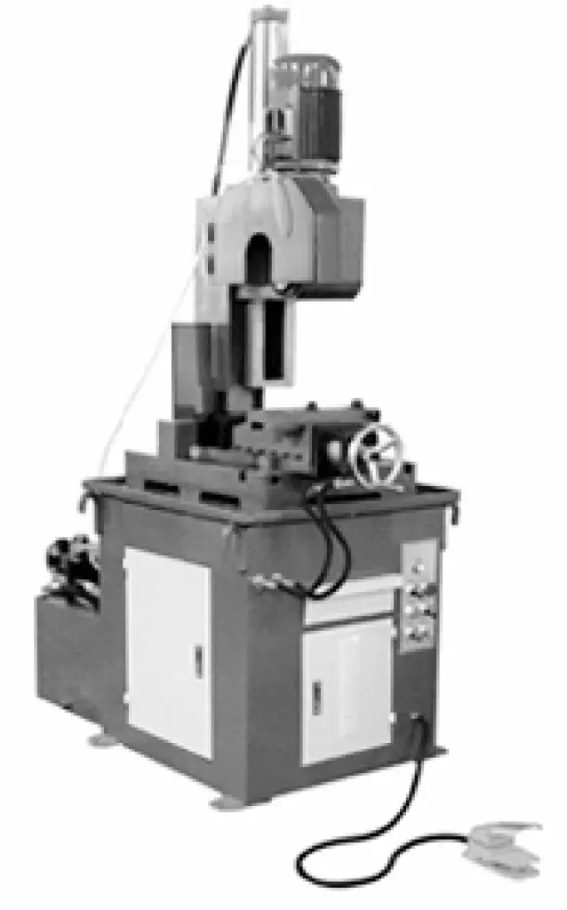
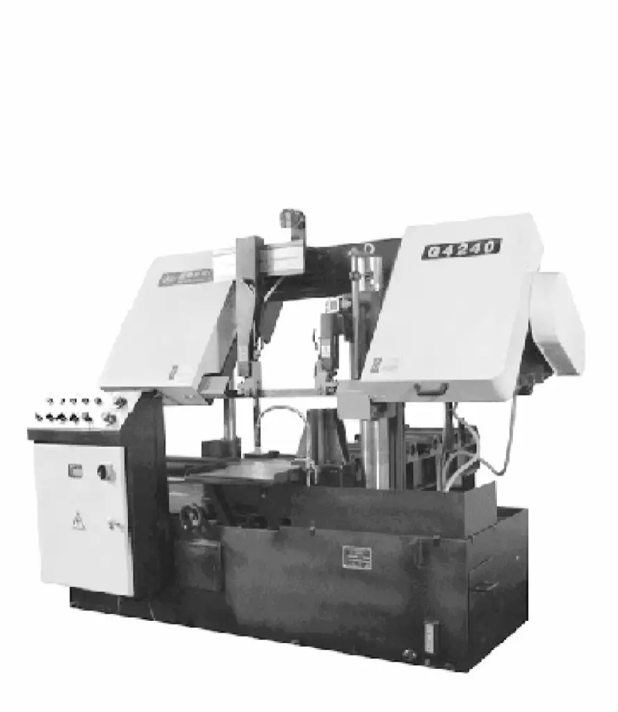
Sawing processing equipment is mainly used for sawing the blank material before pipe fitting forming and the excess material after bending process. The processing equipment used in production includes metal circular saws (Figure 4-53) and band saws (Figure 4-54), etc.
4. Plasma Cutting Processing Equipment
Plasma cutting is mainly used for processing more complex surfaces due to its convenience and ease of operation compared to milling. The cutting processing equipment used on site includes manual plasma cutting machines. However, it is bound to be replaced by machining cutting in future development trends.
5. Laser Tube Cutting Equipment
Laser tube cutting equipment is divided into metal tube laser cutting machines dedicated to tube cutting and laser cutting machines for both metal tubes and plates. The industry generally adopts non-standard laser cutting machine models with metal laser cutting machines plus tube rotating devices, which are more suitable for the cutting processing of round tube intersecting lines.
It is now gradually applied to the cutting processing of square tubes, such as the laser tube cutting machines produced by Amada. There are also those that complete the positioning of the pipe parts by rotating and linear movement of the cutting laser head and robot positioning for loading and unloading, such as the laser tube cutting machines produced by BLM.
The Adige tube laser cutting machine LT823D from the Italian BLM Group (see figure 4-55) is a technically advanced tube laser cutting machine.
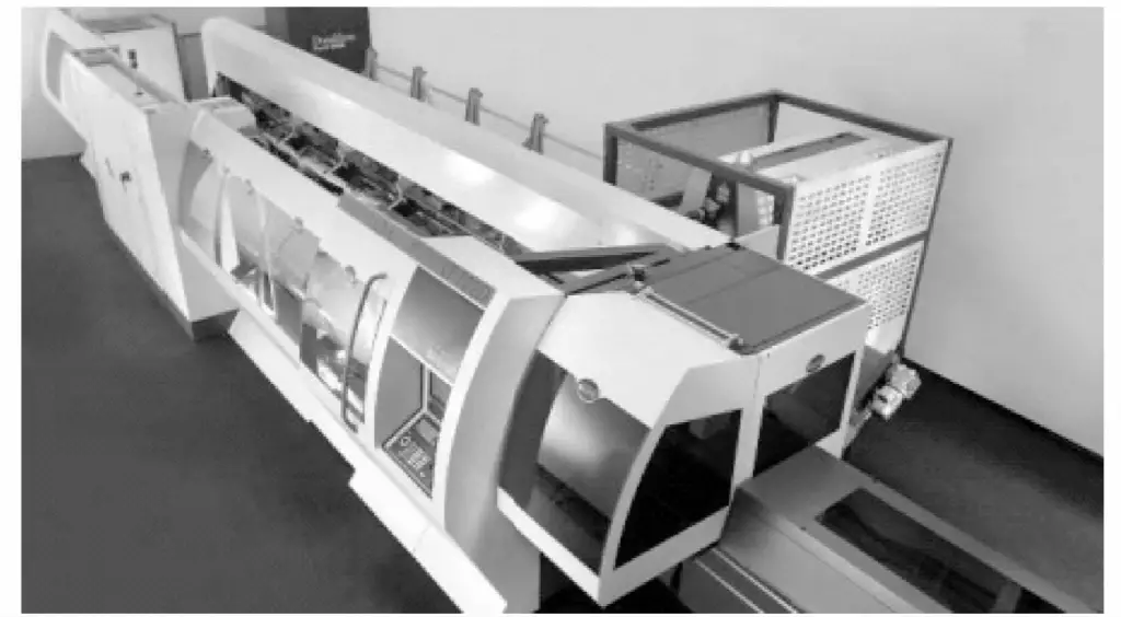
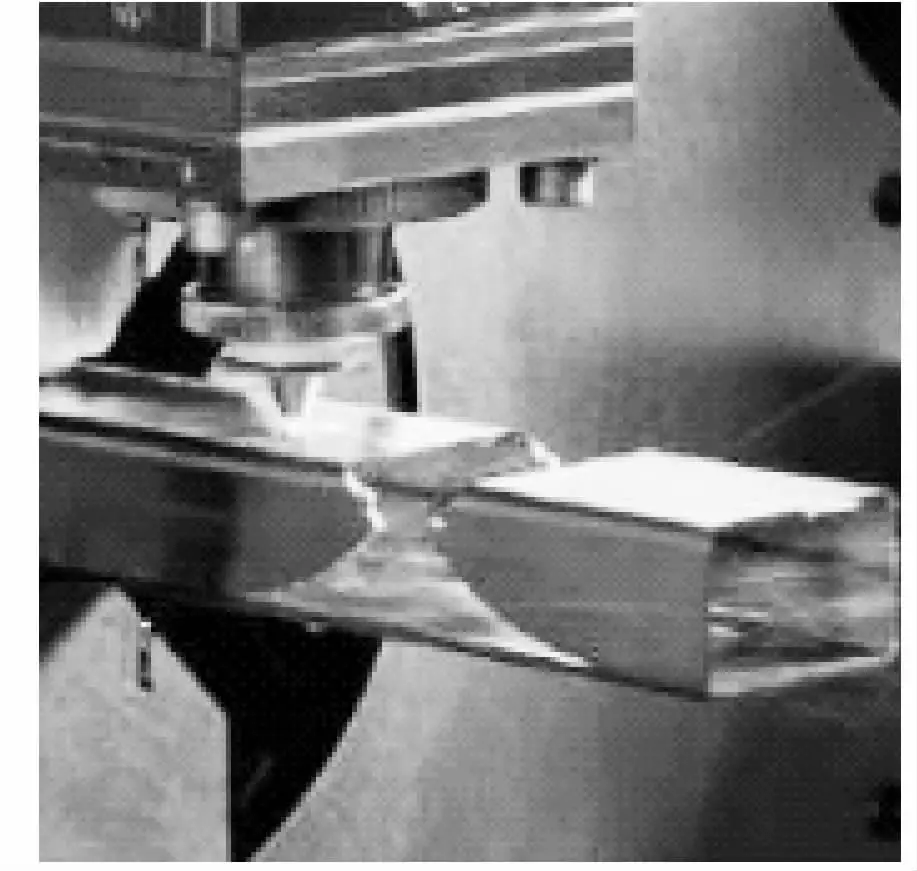
The exquisitely manufactured multi-axis (including swivel head) full CNC tube laser cutting machine has a competitive advantage in the market, surpassing traditional tube processing techniques. Figure 4-56 shows the cutting process of the pipe parts using this equipment, and figure 4-57 shows the composition of the LT823D equipment.
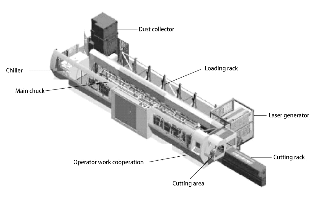
The LT823D cutting machine integrates various processes and procedures of traditional tube processing (such as tube sizing, drilling, milling, grinding, and punching) into one, using single-piece laser cutting to replace traditional processing procedures. It reduces direct and indirect labor; at the same time, laser cutting of tubes improves product quality and precision, and reduces the traditional processing fixtures and setup time before processing.
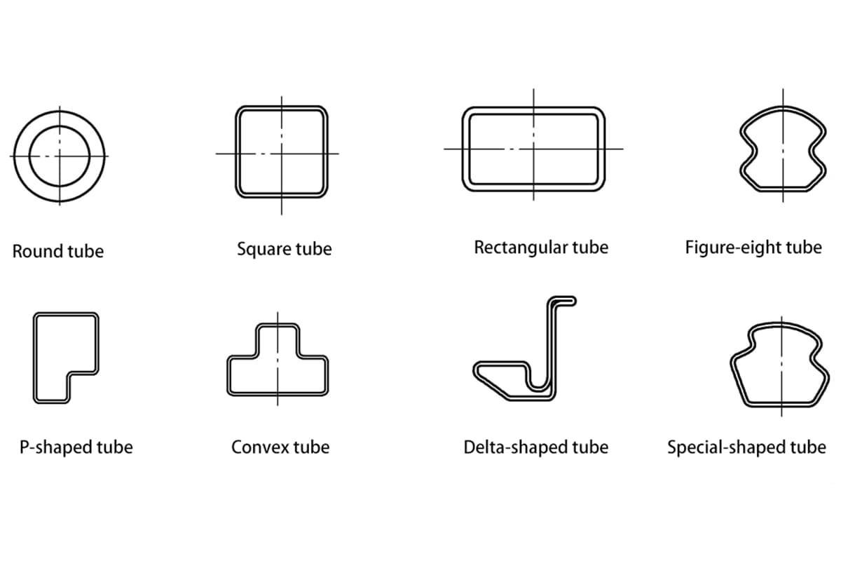
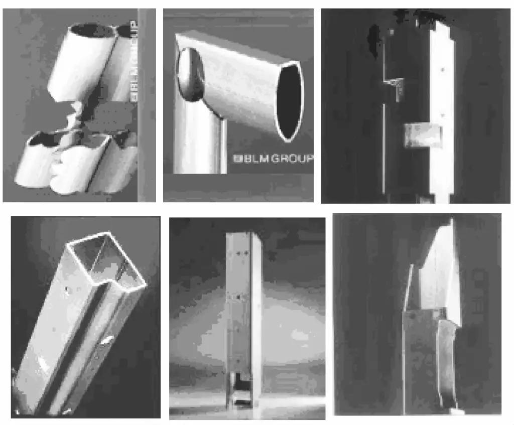
Equipment processing capability: It can process round tubes, square tubes, rectangular tubes, and other special-shaped tubes, including selectively angle iron, I-beams, and flat iron. Under the action of suitable laser cutting auxiliary gases, the equipment can also cut and process carbon steel, alloy steel, stainless steel, and aluminum alloy tubes.
Universally applicable to agricultural and industrial products, such as tooling fixtures, pipe making, pipe processing, medical devices, construction equipment, etc., with the cutting effect shown in Figure 4-58.
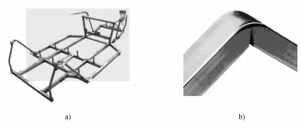
The tooling fixture of the pipe laser cutting machine LT823D is shown in Figure 4-59a, and Figure 4-59b shows an example of the cutting process for bending pipes.
a) Tooling fixtures
b) Cutting process for bending pipes
Since laser cutting requires high processing precision before cutting the pipe, Yituo Company mostly uses the surface processing of formed pipe fittings, therefore, the adopted cutting scheme is laser cutting with a robot combined with a cutting worktable, which is more suitable for cutting pipes and for hollowing out pipes, etc.
The pipe laser cutting machine is designed and manufactured for the needs of oil pipeline equipment, industrial metal pipe hollowing, and processing of special shapes on the pipe walls. The metal pipe laser cutting machine has the following advantages:
1) High-quality cut, minimal deformation, smooth and beautiful appearance.
2) Fast cutting speed, high efficiency, low cost, safe operation, and stable performance.
3) Uses imported servo motors and guide transmission mechanisms for high cutting accuracy.
4) Uses professional software, allowing for the flexible design and processing of various shapes or text, with simple and convenient operation.
5) The laser beam is easy to achieve time or spatial beam splitting, enabling multi-beam processing or sequential processing at multiple stations.
6) The same equipment can not only complete cutting but also achieve laser welding functions.

