Metal Bending Processes: Equipment, Parameters, and Troubleshooting
How do flat sheets become curved parts? Metal bending is key. This article unveils the tools, techniques, and tricks behind…
Imagine transforming a flat, unremarkable sheet of metal into a precisely curved, structurally essential component. This magic of material manipulation is at the heart of bending component manufacturing. From determining the right bending radius to managing springback and selecting the best equipment, the process is both an art and a science. In this article, you’ll uncover the critical techniques and considerations that ensure every bend meets exacting standards, enhancing both the form and function of metal structures. Prepare to master the mechanics of metal bending and achieve flawless results.
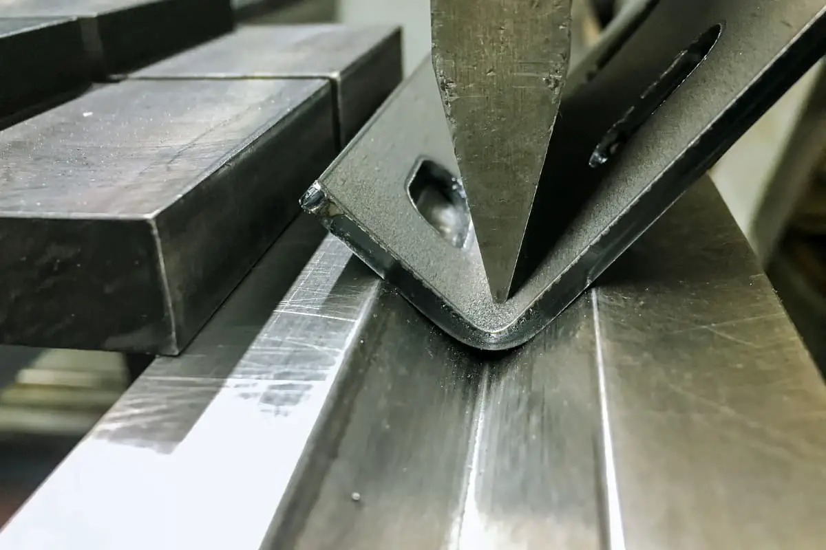
The process of bending materials to a specific angle, curvature, and shape is referred to as bending. Bending is one of the most common methods in material shaping and is extensively used in the fabrication of metal structure components.
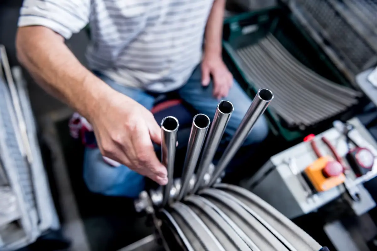
Bending can be categorized into sheet, bar, tube, and profile bending. Due to different cross-sectional shapes, the internal stresses of the materials influence the deformation differently during the bending process, resulting in different patterns.
Based on the shape of the raw materials, bending components can be classified into sheet bending, tube bending, bar bending, and profile bending. Furthermore, bending processes can be categorized, according to the tools and equipment used, into pressing with dies on a common press machine, and bending, roll bending, draw bending, etc. performed on specialized bending equipment.
The materials for bending components are primarily steel plates, aluminum alloy plates, and rolled profiles.
When bending a sheet, the issue to consider is the minimum relative bending radius (R/t).
The minimum bending radius of the material, the unfolding of the bending component, and the springback of the bending component all involve the relative bending radius. During the process analysis calculation, it is necessary to ensure that the relative bending radius is greater than its minimum bending radius.
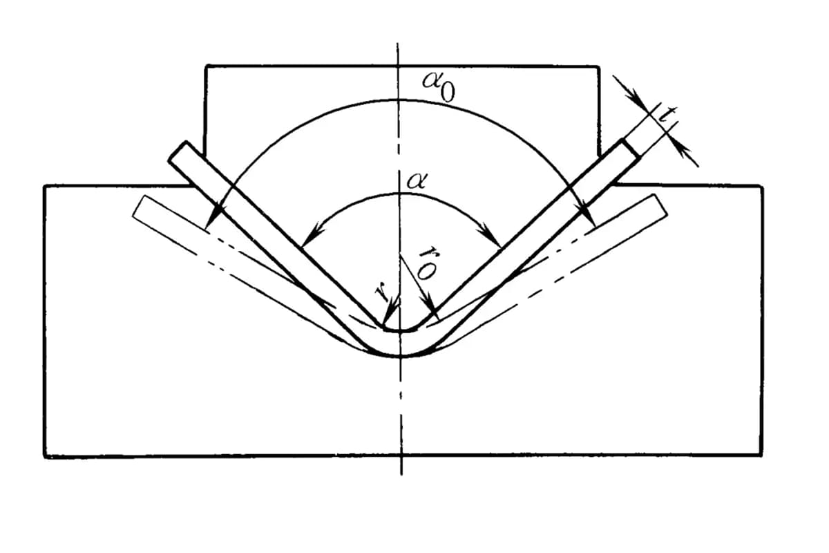
When the bending component is released from the external force after pressing, due to the elastic deformation during bending, changes occur in the angle, fillet radius, and length of the arc of the workpiece, which are inconsistent with the shape when the external force is not removed from the mold.
This phenomenon is known as springback. To consider the springback issue, it is necessary to adjust the relevant dimensions of the mold according to the bending material.
The main factors are the mechanical properties of the material, the relative bending radius, and the shape, the dimensions of the mold, the clearance, and the bending correction force.
1) Mechanical properties of the material. The higher the yield point of the material, the smaller the elastic modulus, the greater the springback.
2) Relative bending radius of the material R/t. The smaller the value of R/t, the smaller the springback.
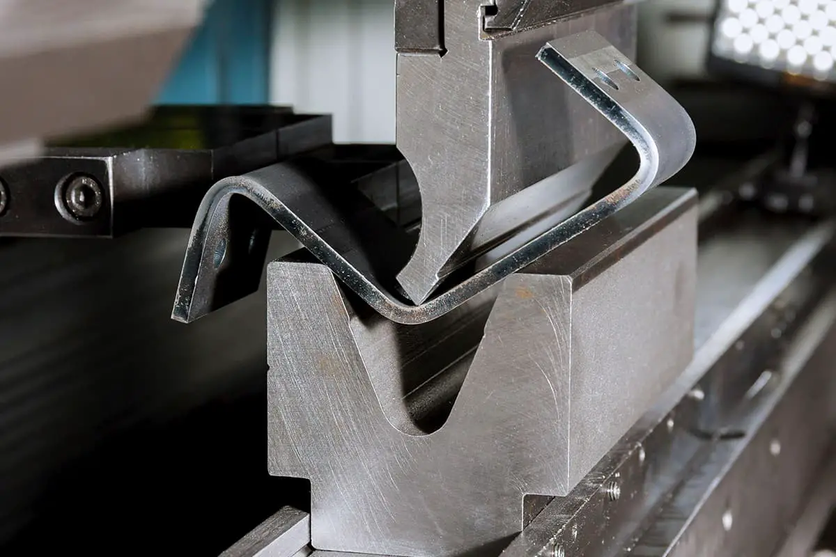
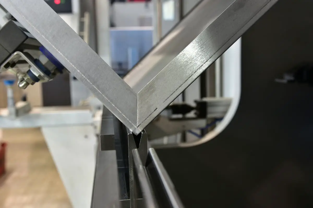
3) Shape of the bent workpiece. Generally, the springback of a U-shaped workpiece pressed out at once is smaller than that of a V-shaped workpiece.
4) Dimensions of the mold. When the radius r of the punch is constant, the springback of the V-shaped bending component decreases as the opening distance of the die increases. The deeper the opening of the U-shaped die, the smaller the springback.
5) Mold clearance. The greater the clearance between the punch and die of the U-shaped bending mold, the greater the springback.
6) Bending correction force. Increasing the correction force can reduce the amount of springback.
Regarding the calculation and mold design of sheet bending, the following issues need to be considered.
1) The relevant dimensions of the bending blank are first calculated, and then determined by test bending.
2) The dimensions of the punch and die of the bending mold are considered according to different requirements for external dimension marking.
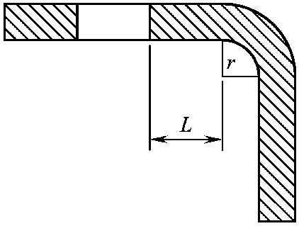
3) When there is a hole in the bending component, the hole must be kept outside the deformation zone to a certain distance, otherwise bending will cause deformation of the hole.
The distance L from the edge of the hole to the center of the bending radius r is related to the thickness of the plate (see Figure 2-17). When the plate thickness t is less than 2mm, the distance L should be greater than 1.5t; when the plate thickness t is more than 2mm, the distance L should be greater than 2t. If the distance L is too small, it is better to drill the hole after bending.
4) The number of bends for some complex-shaped workpieces must be determined based on the actual situation.
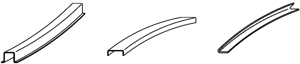
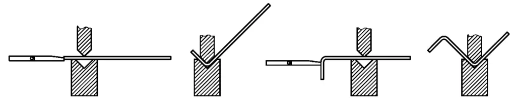
As shown in Figure 2-18, a class of complex-shaped bending components requires specialized molds to complete, and the number of bends must be determined based on the actual situation.
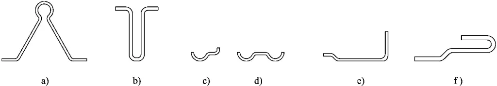
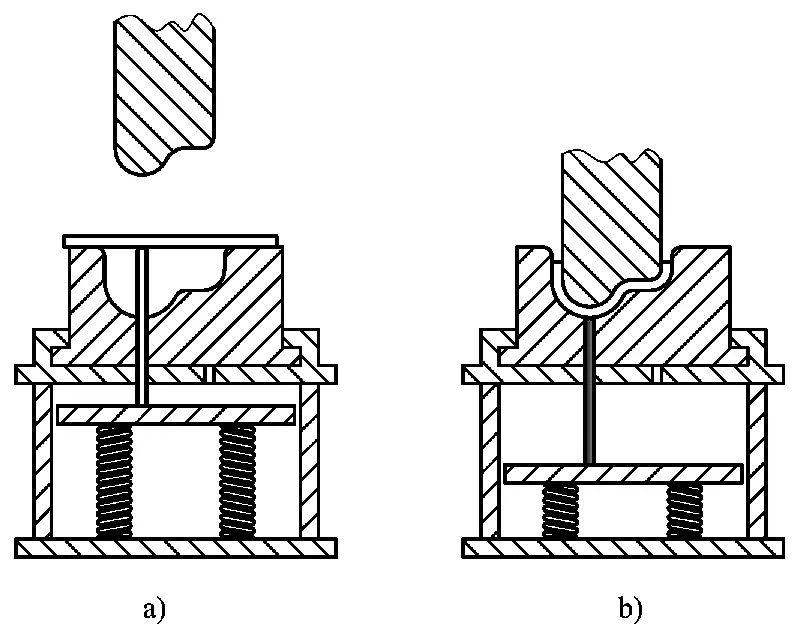
The part shown in Figure 2-18a doesn’t form well under cold pressing, making hot pressing a more appropriate choice. The corresponding mold and forming method are illustrated in Figure 2-19.
The part depicted in Figure 2-18b is better formed through hot pressing, but this approach is inefficient, energy-consuming, and prone to causing stretching injuries. It’s preferable to use a two-step cold pressing method, and the corresponding mold and bending method are shown in Figure 2-20.
The part presented in Figure 2-18c has an asymmetrical cross-section, causing uneven and unstable material flow on both sides during pressing. It’s advisable to add a topping device to the mold, which also facilitates the part’s removal from the mold. The respective mold and press bending method are demonstrated in Figure 2-21.
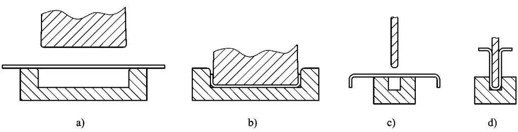
The parts shown in Figures 2-18e and 2-18f both have forward and reverse bends at one end, which cannot be accomplished using a general mold. A two-step press bending method is preferable. After completing the forward and reverse bends at one end (Figure 2-22), proceed with the subsequent bending.
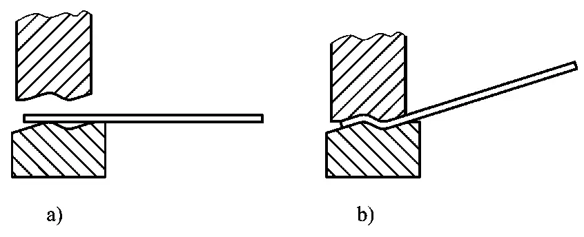
After the first press bending is completed for the part shown in Figure 2-18e, a V-shaped die is used for the second press bending. The part depicted in Figure 2-18f must adopt a method similar to the second press bending of the part shown in Figure 2-18b to complete the subsequent press bending.
Figures 2-23 and 2-24 depict typical profile re-bending components commonly used in locomotives.
Profile bending differs from sheet bending, primarily due to the cross-sectional shape of the profile and its symmetry. Generally, due to the stronger rigidity of the profile, the bending springback of the profile is less than that of the sheet. However, some profiles have asymmetrical cross-sections, causing inconsistent wing surface springbacks during bending, leading to material instability and resulting in twisted deformation.
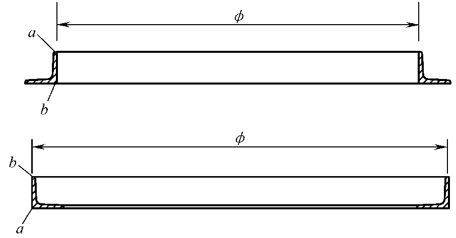
The angle steel bending component shown in Figure 2-23 is a typical example of asymmetrical springback. During bending, the springback at point ‘a’ on its wing surface is the greatest, while the springback at point ‘b’ is smaller, causing the angle steel bending component to undergo spiral twisting. When designing the angle steel bending mold, this inconsistency in springback must be taken into account.
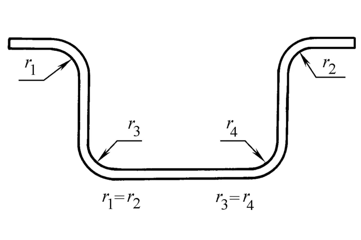
The profile bending component shown in Figure 2-24 is a typical example of symmetrical springback, where the wing surface springback tends to be consistent, and the profile bending component does not exhibit any twisting.
The wing surface of the profile does have an impact on springback, but how significant this impact is currently lacks an accurate conclusion.
In the practice of profile bending, an empirical formula and coefficient values for profile bending mold design have been summarized for your reference (see Figure 2-25 and Table 2-1).
The calculation formula for the convex mold radius is:
Where:
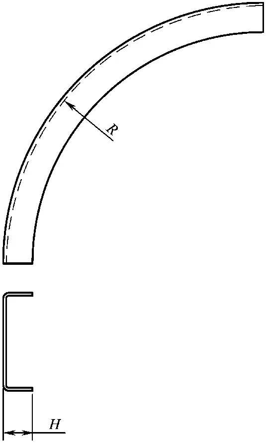
Table 2-1: Rebound Value A for Bent Channel Steel
| No. | R/H Value | A Value | No. | No. | A Value | No. | R/H Value | A Value |
| 1 | 5 | 0. 2 | 7 | 11 | 0. 45 | 13 | 17 ~ 23 | 0. 68 |
| 2 | 6 | 0. 24 | 8 | 12 | 0. 49 | 14 | 24 ~ 38 | 0. 70 |
| 3 | 7 | 0. 28 | 9 | 13 | 0. 53 | 15 | 39 ~ 57 | 0. 72 |
| 4 | 8 | 0. 34 | 10 | 14 | 0. 57 | 16 | 58 ~ 65 | 0. 76 |
| 5 | 9 | 0. 39 | 11 | 15 | 0. 61 | 17 | 66 ~ 76 | 0. 86 |
| 6 | 10 | 0. 42 | 12 | 16 | 0. 65 | 18 | >88 | 1. 00 |
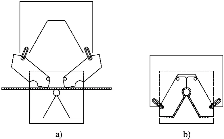
In designing the bending mold for channel steel, consideration should be given to the potential instability and twisting of the wing surface during bending, and appropriate measures should be taken. Here, two mold control methods are introduced for reference.
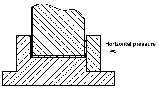
Method One: When the pressure equipment itself has both vertical and horizontal hydraulic cylinders, the vertical force is used for bending, and the horizontal force is used to suppress twisting. The structure of the mold is shown in Figure 2-26. This mold is simple to manufacture, convenient to use, and the workpiece is easy to demold during bending.
Method Two: When the pressure equipment only has a vertical hydraulic cylinder, the mold structure shown in Figure 2-27 can be used.
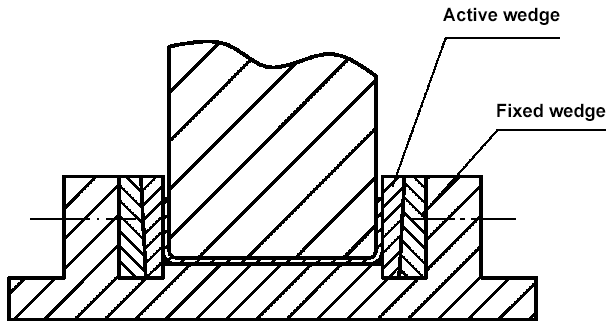
The movable mold iron in the mold can move upward when the punch rises after bending, increasing the gap between the punch and die, making it easy for the workpiece to demold.
Corrugated sheet is a common bent component, also known as a wave component (Figure 2-28). This wave component cannot be completed in one forming process, but must be pressed one wave at a time. The form of its mold is shown in Figure 2-29.
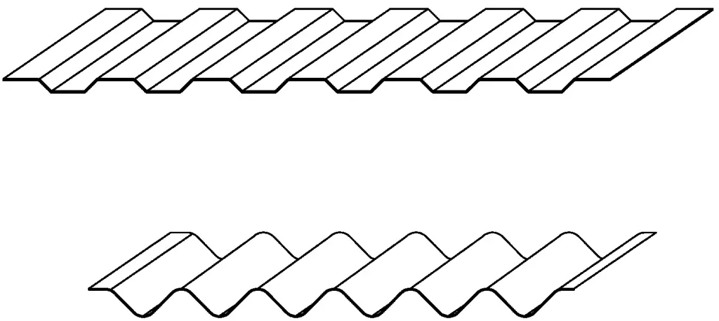
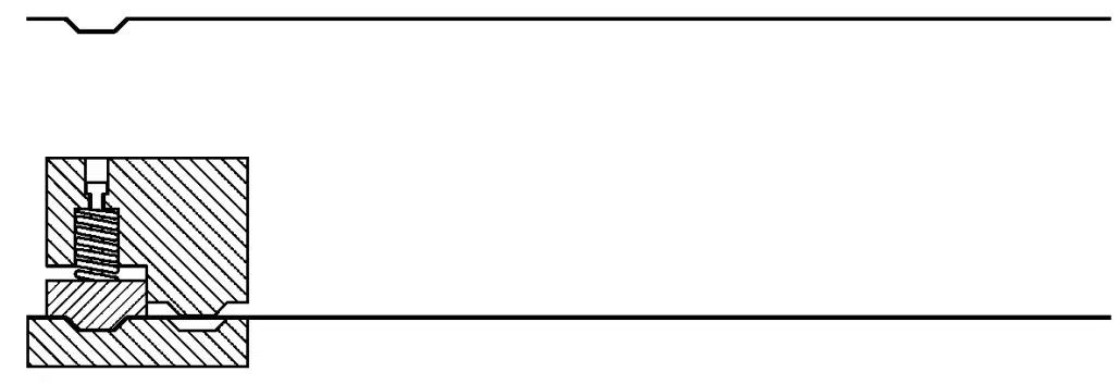
As shown in the figure, this is a double-waveform mold. First, a waveform is pressed at one end of the sheet. When the first waveform is pressed, the material flows from both sides of the mold to the center, allowing for bidirectional material flow.
After the first waveform is formed, it is placed in the left positioning die, the punch descends, and the spring-loaded punch first presses the first waveform. The punch continues to descend, starting to press the second waveform. The material on the right side of the mold flows to the left, allowing for unidirectional material flow, which can supplement the material for pressing the second waveform.
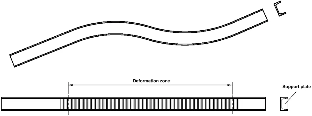
Lateral bending of channel steel is relatively rare (Figure 2-30), and its bending method is also quite unique.
Before bending the channel steel, a support plate needs to be placed in the groove of the deformation zone of the channel steel. During bending, a heated pressing method must be used.
The bending mold for basin-shaped channel steel is a combination of several parts (Figure 2-31). The left and middle punches are fixed on the connecting plate, and the right punch is connected by bolts, leaving a gap of 1-2mm between the right punch and the middle punch. The left, middle, and right punches are connected as a whole by bolts and fixed on the connecting plate.
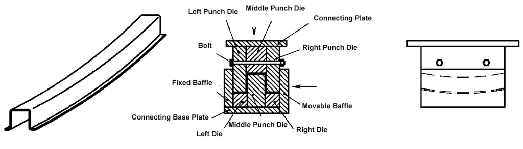
When bending the workpiece, place the basin-shaped channel steel in the die, then use the horizontal hydraulic cylinder to push the movable baffle so that it fits tightly against the die body, and then drive the vertical hydraulic cylinder to make the die body descend for bending.
The quality of a bent part largely depends on the precision of its positioning, and whether the sequence of bending and the positioning benchmark are reasonable. Bending positioning can be roughly divided into front-end positioning, back-end positioning, side auxiliary positioning, centerline positioning, and auxiliary line positioning. Each type of positioning has its own characteristics, and their appropriate selection is crucial.
(1) Front-end positioning (back gauging) is a common and straightforward method of positioning. Currently, bending machines are equipped with multi-axis CNC back-end positioning devices that are easy to use and accurate in positioning. However, when there are multiple bends, the base of the subsequent positioning can be affected by the precision of previous bending due to the change in the positioning base (Figure 2-32).
Although back-end positioning is not as convenient as front-end positioning, this method uses the same positioning base regardless of how many bends are made. Therefore, the bending dimensions are not affected by other factors (Figure 2-33).
When making multiple parallel bends on narrow and long parts, to ensure that each bending line is parallel to each other, in addition to setting up front-end or back-end positioning, auxiliary positioning should also be set along the length direction at the edge of the material (Figure 2-34).
Some bent parts are difficult to accurately position using front-end or back-end positioning methods. It is recommended to use the centerline positioning method, as shown in Figure 2-35.
When making multiple bends with a large radius, if the punch has difficulty accurately capturing the bending line, it is recommended to use the auxiliary line positioning method (Figure 2-36).
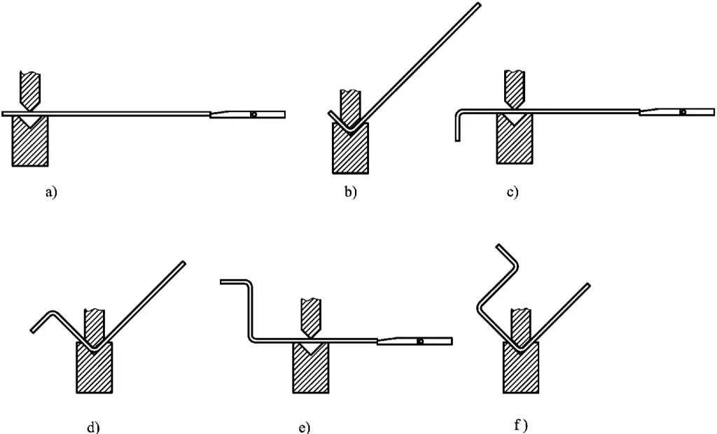
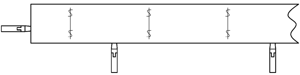
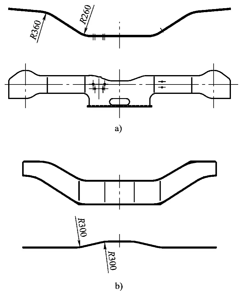
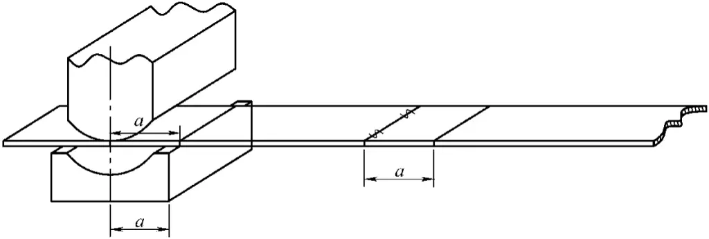
Figure 2-35a displays a narrow and long bent part with four bends, each pair having the same bending radius. According to the bending sequence, the two ends should be bent first with a radius of R360, then the middle should be bent with a radius of R260. This requires two mold changes, which can be quite cumbersome, and involves frequent handling of the workpiece. Here, we introduce a type of combination bending mold for reference.
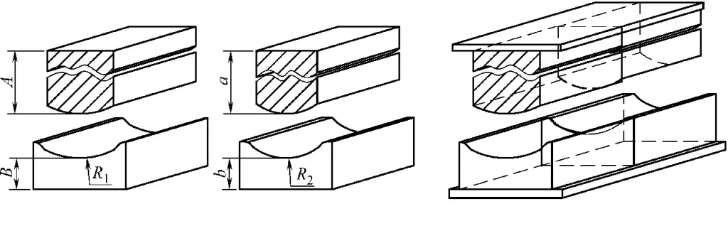
The combination bending mold is shown in Figure 2-37. During design, molds for both bending radii should not be excessively long, they only need to be slightly wider than the width of the workpiece. The convex mold size A of Mold (1) and Mold (2) should equal ‘a’, and the concave mold size B should equal ‘b’.
After Mold (1) and Mold (2) are processed, they are combined to form Mold (3). That is, two sets of equal-height convex molds and the upper seat plate form the upper mold of Mold (3), and two sets of equal-height concave molds and the lower seat plate form the lower mold of Mold (3).
The use of this combination mold not only reduces the number of mold installations and the frequency of workpiece handling, thereby decreasing labor intensity, but also facilitates quality inspection during the bending process.
The types of molds for bent parts can be classified according to the shape of the bent parts, the material of the bent parts, the material of the mold, and the equipment applicable to the mold. These bending molds vary greatly in structure.
This includes single-angle bending molds, double-angle bending molds (Z-shaped bending, U-shaped bending), and multi-angle bending molds.
This includes sheet bending molds, profile bending molds, pipe bending molds, and rod (wire) bending molds.
This includes all-metal molds and polyurethane rubber bending molds (where polyurethane rubber replaces the steel die).
This includes bending molds for general presses, bending machines, and benders.
The bending process is primarily carried out on mechanical presses and sheet metal bending machines.
Figure 2-38 illustrates the structure of a U-shaped connector and its bending mold.
This mold bends the blank into shape in one press, producing two pieces at once.
The blank is placed on the stock support block 12, which has a groove machined into it, ensuring high precision in part positioning. When the press slide descends, the punch 5 makes contact with the blank first, pressing it down.
The blank slides along the fillet of the sliding die 11, entering the die cavity, and is bent into a U-shape. As the slide continues to descend, the inclined wedge 3 contacts the sliding die 11, causing the sliding die 11 to move towards the center of the mold within the groove of the die base 9, correcting the sides of the part.
When the press slide returns, the inclined wedge 3 moves upwards, and the sliding die 11 moves towards the outside of the mold under the action of the bolt 7 and spring 8. The stock support block 12 moves upwards under the action of spring 14, pushing the part out of the die.
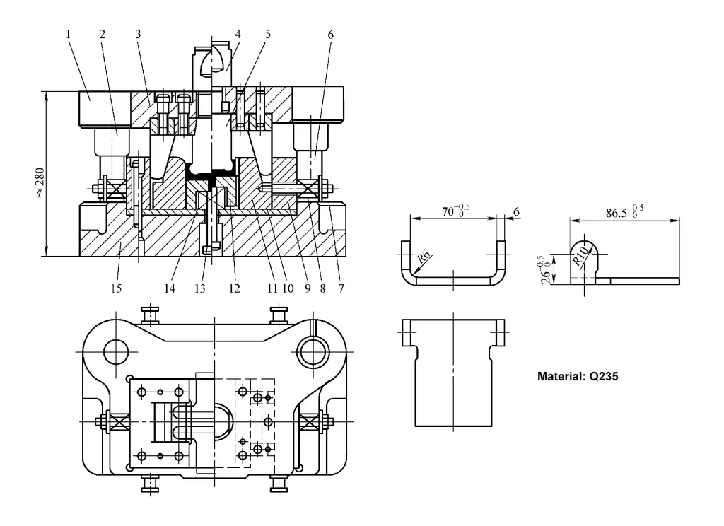
1- Upper mold base
2- Guide bush
3- Slant mold
4- Mold handle
5- Punch mold
6- Guide post
7, 13- Bolts
8, 14- Springs
9- Die base
10- Spacer plate
11- Slide mold form die
12- Material support block
15- Lower mold base
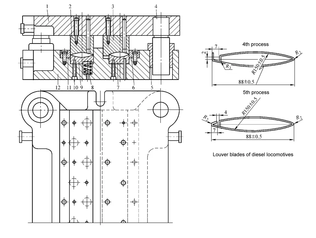
The louver blade of an internal combustion locomotive is formed by bending a 1mm thick steel plate, requiring five operations to shape.
Figure 2-39 shows the bending mold structure of the first to third operations of the louver blade and the schematic diagram of blade bending; Figure 2-40 shows the bending mold of the fourth to fifth operations and the final shape of the blade, i.e., the workpiece diagram. The mold is a set of single-operation molds on a large mold frame, similar to a multi-station combination mold.
In the bending mold shown in Figure 2-39, the blank is placed on the material support plate 18 of the first operation press bending mold, positioned by the positioning plate 15, and the hook-shaped head at one end of the blank is pressed out by the downward movement of the slider.
The blank with the pressed hook head is placed on the die 13 of the second operation press bending mold, positioned by the positioning plate 14, and the arc in the middle part of the blank is pressed out. The blank with the pressed arc is placed on the rubber block 11 of the third operation press bending mold, positioned by the hook head positioning plate 12, and the punch mold 6 bends the blank in half.
In the bending mold shown in Figure 2-40, the folded blank is placed on floating die (I) 9 of the fourth operation press bending mold, positioned by one end of the fold, and the other end is bent.
The already folded blank is placed on the die (II) 7 of the fifth operation bending mold, with the folded end aligned with the groove in the inlaid block (II) 6, and the folded edge with the hook head is pressed to make it fit with the middle arc surface, completing the final shape of the workpiece.
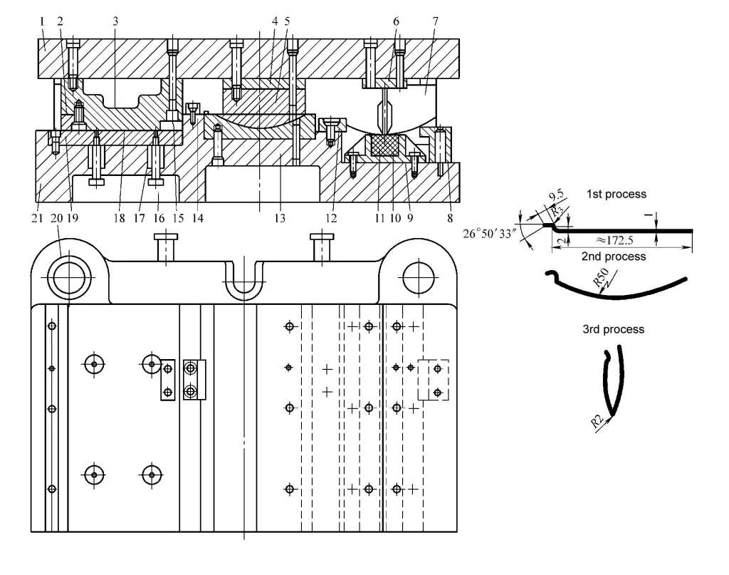
1-Upper Mold Base
2-Insert
3-Punch
4-Pad
5-Punch
6-Punch
7-Guide Post
8-Locating Plate
9-Container Frame
10-Round Steel
11-Rubber Block
12-Locating Plate
13-Die
14-Locating Plate
15-Locating Plate
16-Bolt
17-Spring
18-Support Plate
19-Insert
20-Guide Bush
21-Lower Mold Base
1-Upper Mold Base
2-Punch (I)
3-Punch (II)
4-Guide Post
5-Guide Bush
6-Insert (II)
7-Die (II)
8-Spring
9-Die (I)
10-Bolt
11-Insert
12-Lower Mold Base