I. Bending Forming Principle
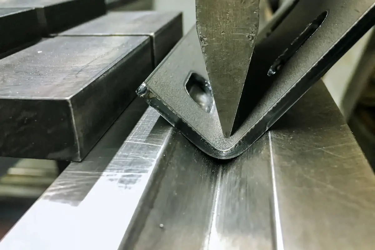
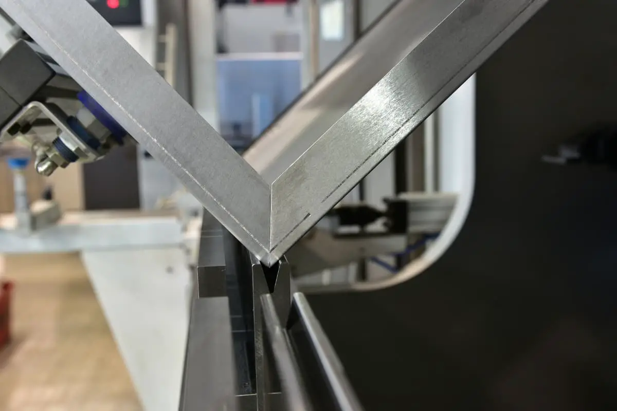
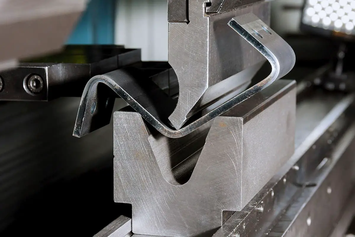
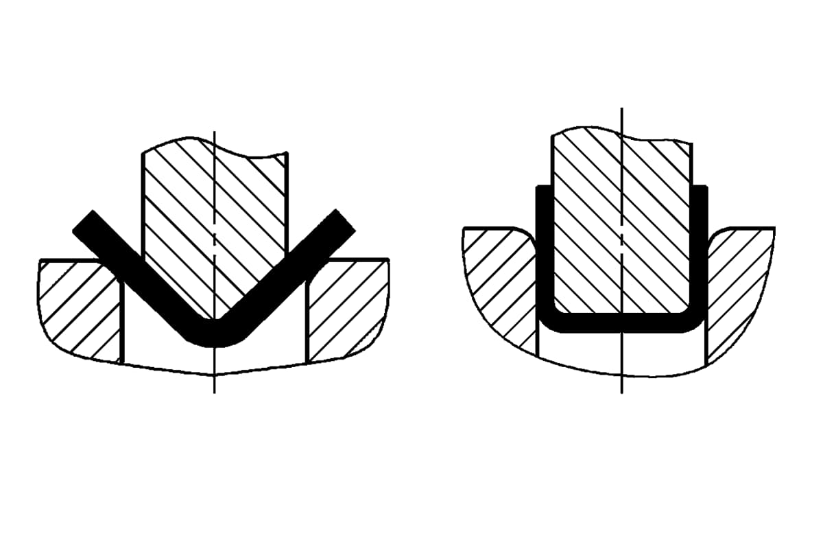
Bending is a method of using dies on a bending machine to bend metal sheets into a certain angle, primarily accomplishing straight-line bends.
A bending machine forms a bend in one stroke. Optimal control of springback can be achieved with bending forming. Over 80% of railcar bends are made by bending forming, which is a key process. The precision of parts formed by bending directly impacts the assembly accuracy of the railcars.
II. Types of Bends
1. By forming material:
- carbon steel bends
- stainless steel bends
- aluminum alloy bends
2. By forming corner radius:
- small corner radius forming
- large corner radius forming
III. Bending Forming Process
The bending forming process primarily considers bending force, bending dies, bending sequence design, as well as workpiece and die interference analysis, bending deflection compensation, etc.
1. Bending Force Calculation
The formula for calculating bending force is as follows:
P = 1. 42*L*Rm*S2/(1000V)
In the formula,
- P – bending force (kN);
- L – the length of the bent part (mm);
- Rm – tensile strength (N/mm2);
- S – the thickness of the sheet (mm);
- V – the die slot width (mm), which is generally 8-10 times the thickness of the sheet;
- R – the bending radius, where R = 5V/32.
Figure 3-114 provides a schematic illustration of the calculation of bending force and the minimum flanging height.
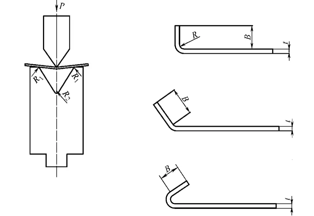
The bending angle has a certain relationship with the minimum flanging height B, as detailed in Table 3-89.
Table 3-89: Relationship Between Bending Angle and Minimum Flanging Height
| Angle | B |
| 165° | 0. 58 V |
| 135° | 0. 60 V |
| 120° | 0. 62 V |
| 90° | 0. 65 V |
| 60° | 0. 80 V |
| 45° | 1. 00 V |
| 30° | 1. 30 V |
Under standard bending radius conditions, the bending force can be directly selected from Table 3-90.
You can also use the following bending force calculator:
2. Bending Radius Requirements
Cracking is a primary form of damage in bent parts. The bending radius of the part cannot be less than the minimum bending radius of the selected material. Recommended bending radii for railcar materials can be found in Tables 3-91 through 3-97. The actual bending radius used must not be less than the recommended values in these tables, or the bent part will crack and be scrapped.
3. Selection of Bending Die
Two factors should be considered: first, the die is selected based on the bending radius required by the drawing; second, whether there will be interference during bending. If interference occurs, the bending sequence needs to be adjusted or the die needs to be replaced. Figure 3-115 provides a graphical method to determine whether bending interference occurs.
4. Calculation of Unfolded Dimensions of Bent Parts
There are three methods for calculating the blank size of bent railcar stamping parts: neutral layer calculation method, direct thickness reduction method, and drawing method. The neutral layer calculation method uses the principle that the length of the neutral layer remains constant before and after bending, as described in earlier sections.
Table 3-90: Bending Force Table

| V | R | B |  | |||||||||||||||||
| 0.5 | 0.8 | 1 | 1.2 | 1.5 | 2 | 2.5 | 3 | 4 | 5 | 6 | 8 | 10 | 12 | 15 | 20 | 25 | 30 | |||
| 4 | 0.7 | 2.6 | 40 | 105 | T = 420 ~ 480N/ mm2 (C = 1) P = (kN/ m) | |||||||||||||||
| 6 | 0.9 | 3.9 | 26 | 69 | 106 | 153 | ||||||||||||||
| 8 | 1.5 | 5.2 | 20 | 55 | 80 | 115 | 180 | |||||||||||||
| 10 | 1.7 | 6.5 | 41 | 65 | 95 | 145 | 260 | |||||||||||||
| 12 | 2 | 7.8 | 55 | 80 | 120 | 215 | 335 | |||||||||||||
| 16 | 2. 7 | 10.4 | 60 | 90 | 160 | 250 | 360 | |||||||||||||
| 20 | 3. 4 | 13 | 75 | 130 | 200 | 290 | 520 | |||||||||||||
| 24 | 3. 9 | 15.6 | 106 | 166 | 240 | 426 | 666 | |||||||||||||
| 30 | 5 | 20 | 140 | 190 | 340 | 540 | 770 | |||||||||||||
| 35 | 6 | 23 | 170 | 300 | 460 | 660 | ||||||||||||||
| 40 | 7 | 26 | 150 | 260 | 400 | 580 | 1030 | |||||||||||||
| 50 | 8.5 | 32 | 210 | 320 | 460 | 820 | 1280 | |||||||||||||
| 55 | 9 | 36 | 300 | 420 | 750 | 1170 | ||||||||||||||
| 60 | 10 | 39 | 270 | 390 | 690 | 1070 | ||||||||||||||
| 70 | 11.7 | 45 | 330 | 590 | 920 | 1320 | ||||||||||||||
| 80 | 13.5 | 52 | 290 | 520 | 800 | 1160 | 1800 | |||||||||||||
| 90 | 15 | 58 | 460 | 710 | 1030 | 1600 | ||||||||||||||
| 100 | 17 | 65 | 410 | 640 | 930 | 1440 | ||||||||||||||
| 120 | 20 | 78 | 540 | 770 | 1200 | |||||||||||||||
| 140 | 24 | 91 | 660 | 1030 | 1830 | |||||||||||||||
| 200 | 31 | 130 | 719 | 1278 | 1997 | |||||||||||||||
| 250 | 39 | 163 | 1020 | 1598 | 2300 | |||||||||||||||
| 300 | 47 | 195 | 852 | 1331 | 1917 | |||||||||||||||
| 350 | 55 | 228 | 1141 | 1643 | ||||||||||||||||
Table 3-91: Bending Radii of Carbon Structural Steel and High-Strength Low-Alloy Structural Steel
| Material Grade | Bending Direction | Plate Thickness | |||||||||||||||
| >1 ≤1.5 | >1.5 ≤2.5 | >2.5 ≤3 | >3 ≤4 | >4 ≤5 | >5 ≤6 | >6 ≤7 | >7 ≤8 | >8 ≤10 | >10 ≤12 | >12 ≤14 | >14 ≤16 | >16 ≤18 | >18 ≤20 | >20 ≤25 | >25 ≤30 | ||
| Q235 | t | 1.6 | 2. 5 | 3 | 5 | 6 | 8 | 10 | 12 | 16 | 20 | 25 | 28 | 36 | 40 | 50 | 60 |
| n | 1.6 | 2. 5 | 3 | 6 | 8 | 10 | 12 | 16 | 20 | 25 | 28 | 32 | 40 | 45 | 55 | 70 | |
| Q275 | t | 2 | 3 | 4 | 5 | 8 | 10 | 12 | 16 | 20 | 25 | 28 | 32 | 40 | 45 | 55 | 70 |
| n | 3 | 3 | 4 | 6 | 10 | 12 | 16 | 20 | 25 | 32 | 36 | 40 | 45 | 50 | 60 | 75 | |
| 09CuPCrNi – B | t | 2 | 3 | 4 | 5 | 8 | 10 | 12 | 16 | 20 | 25 | 28 | 32 | 40 | 45 | 55 | 70 |
| n | 3 | 3 | 4 | 6 | 10 | 12 | 16 | 20 | 25 | 32 | 36 | 40 | 45 | 50 | 60 | 75 | |
| 09CuPCrNi – A | t | 2.5 | 4 | 5 | 6 | 8 | 10 | 12 | 16 | 20 | 25 | 32 | 36 | 45 | 50 | 65 | 80 |
| n | 2.5 | A | 5 | 8 | 10 | 12 | 16 | 20 | 25 | 32 | 36 | 40 | 50 | 63 | 75 | 90 | |
| Q345 Q345R | t | 2.5 | A | 5 | 6 | 8 | 10 | 12 | 16 | 20 | 25 | 32 | 36 | 45 | 50 | 65 | 80 |
| n | 2.5 | 4 | 5 | 8 | 10 | 12 | 16 | 20 | 25 | 32 | 36 | 40 | 50 | 63 | 75 | 90 | |
1. ‘t’ denotes bending perpendicular to the rolling direction, ‘n’ denotes bending parallel to the rolling direction.
2. The above data is suitable for 90-degree bends.
Table 3-92: Standard Fillet Radius for Quenched and Tempered High-Strength Structural Steel Plates
| Material Grade | Plate Thickness Between 3-16mm | |
| Bending Perpendicular to the Rolling Direction | Bending Parallel to the Rolling Direction | |
| Q460 | 3t | 4t |
| Q500 | 3t | 4t |
| Q550 | 3t | 4t |
| Q620 | 3t | 4t |
| Q690 | 3t | 4t |
| Q890 | 3t | 4t |
| Q960 | 4t | 5t |
Table 3-93: Standard Bending Radii for Austenitic Stainless Steel Plates (Unit: mm)
| Plate Thickness | SUS301L -LT/ DLT1 ST | SUS301L – MT1 HT | SUS304 |
| 0.6 | — | 2. 0 | 0.6 |
| 0.8 | 2. 0 | 3 | 0.8 |
| 1 | 2. 0 | 3. 0 | 1. 0 |
| 1.2 | 2. 0 | 3. 0 | 1. 2 |
| 1.5 | 2. 0 | 5. 0 | 1. 5 |
| 2 | 3. 0 | 7. 0 | 2. 0 |
| 2.5 | 3. 0 | 10. 0 | 2. 5 |
| 3 | 5. 0 | 13. 0 | 3. 0 |
| 4 | 7. 0 | 19. 0 | 4. 0 |
| 4.5 | 7. 0 | 19. 0 | 4. 5 |
| 5 | — | — | 5. 0 |
| 6 | — | — | 6. 0 |
Table 3-94: Standard Bending Radii for 1.4003 Stainless Steel
(Unit: mm)
| Plate Thickness | Bending Radius | |
| Bending Perpendicular to the Rolling Direction | Bending Parallel to the Rolling Direction | |
| >1 ~1.5 | 2 | 3 |
| >1.5 ~ 2.5 | 3 | 3 |
| >2.5 ~3 | 4 | 4 |
| >3 ~4 | 5 | 6 |
| >4 ~5 | 8 | 10 |
| >5~6 | 10 | 12 |
| >6~7 | 12 | 16 |
| >7~8 | 16 | 20 |
| >8 ~10 | 20 | 25 |
| >10 ~12 | 25 | 30 |
Table 3-95: Standard Bending Radii for ENAW5052 (Aluminum-Magnesium 2.5) Aluminum Alloy
(Unit: mm)
| Condition | Nominal Thickness / mm | Bending Radius | ||
| Exceeding | To | 180° | 90° | |
| O/ H111 | 1.5 | 3 | 0.5t | 0.5t |
| 3.0 | 6 | — | 1.0t | |
| 6.0 | 12.5 | — | 2.0t | |
Table 3-96: Standard Bending Radii for ENAW5083 (Aluminum-Magnesium 4.5, Manganese 0.7) Aluminum Alloy
(Unit: mm)
| Condition | Nominal Thickness / mm | Bending Radius | ||
| Exceeding | To | 180° | 90° | |
| O/ H111 | 0.5 | 1.5 | 1.0t | 1.0t |
| 1.5 | 3.0 | 1.5t | 1.0t | |
| 3.0 | 6.0 | — | 1.5t | |
| 6.0 | 12.5 | — | 2.5t | |
Table 3-97: Standard Bending Radii for ENAW6082 (Aluminum-Silicon-Magnesium-Manganese) Aluminum Alloy
(Unit: mm)
| Condition | Nominal Thickness | Bending Radius | ||
| Exceeding | To | 180° | 90° | |
| O | ≥0.4 | 0.5 | 1.0t | 0.5t |
| 1. 5 | 3.0 | 1.0t | 1.0t | |
| 3.0 | 6.0 | — | 1.5t | |
| 6.0 | 12.5 | — | 2.5t | |
| T4 | ≥0.4 | 1.5 | 3. 0t | 1.5t |
| 1.5 | 3.0 | 3. 0t | 2.0t | |
| 3.0 | 6.0 | — | 3.0t | |
| 6.0 | 12.5 | — | 4.0t | |
| T6 | ≥0.4 | 1.5 | — | 2.5t |
| 1.5 | 3.0 | — | 3.5t | |
| 3.0 | 6 | — | 4.5t | |
| 6 | 12.5 | — | 6.0t | |
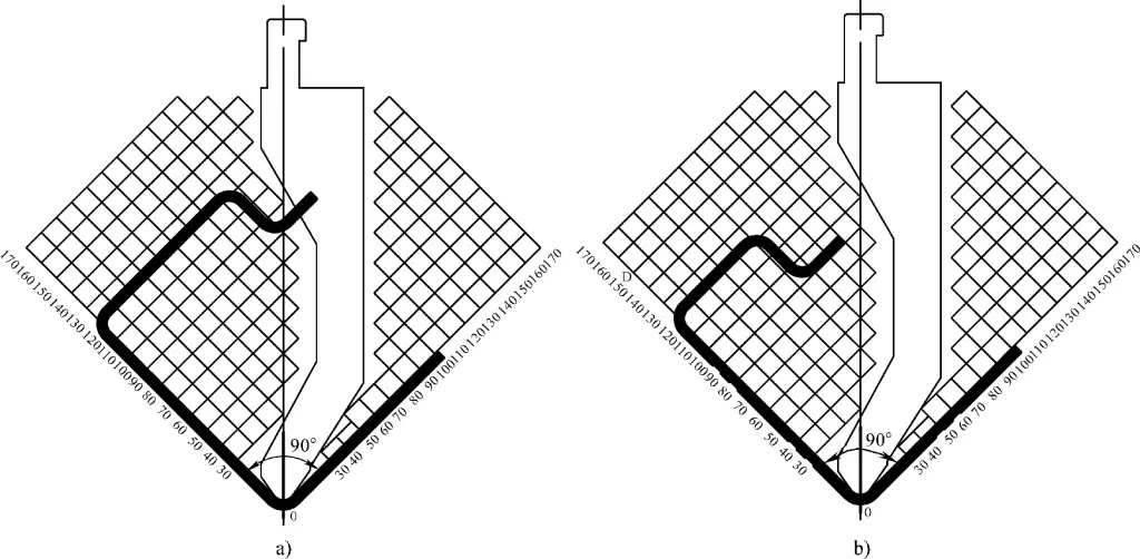
a) Interference State
b) Non-Interference State
1) Direct Subtraction of Sheet Thickness Method (Figure 3-116):

- When the sheet thickness is 1≤6mm, the bend corner radius is 2t≤R, R≥1, and the bending angle is 90°,
Blank length: L = L1 + L2 – 2t (Equation 3-35) - When the sheet thickness is t≤6mm, the bend corner radius is 2t≤R, R≥t, and the bending angle is 135°,
Blank length: L = L1 + L2 – t (Equation 3-36)
Given that the material thickness, bend corner radius, and width of the lower die V-groove remain consistent with the values in Table 3-98, for SUS301L stainless steel 90° bends, the calculation of the developed length deducts one λ value per bend.
2) Graphical Method:
When the structure of the bend is complex, with multiple corner radii and forming angles, the above calculation methods may lead to errors. Employing the graphical method to measure the neutral layer can quickly and accurately determine the developed dimensions.
IV. Bending Forming Equipment
1. Technical Parameters of CNC Bending Machine
The CNC bending machine is the most widely used equipment for bending components in rail passenger cars. Table 3-99 presents the technical parameters of some bending machines manufactured by Huangshi Forging Machine Tool Co., Ltd.
Table 3-98: Calculation Parameters for the Developed Length of SUS301L Series Steel Plate Bends
| Material | Sheet Thickness | Standard Corner Radius R | Reduction Value λ | Minimum Flange | Lower Die V-Groove Width |
| Stainless Steel LT,ST, DLT | 1.0 | 2.0 | 2.4 | 10 | 15 |
| 1.5 | 2.0 | 3.1 | 10 | 15 | |
| 2.0 | 3.0 | 4.3 | 15 | 20 | |
| 2.5 | 3.0 | 5.0 | 20 | 25 | |
| 3.0 | 5.0 | 6.7 | 20 | 30 | |
| 4.0 | 7.0 | 9.0 | 25 | 35 | |
| Stainless Steel MT, HT | 0.8 | 3.0 | 2.4 | 10 | 15 |
| 1.0 | 3.0 | 2.7 | 10 | 15 | |
| 1.5 | 5.0 | 4.2 | 15 | 20 | |
| 2.0 | 7.0 | 5.8 | 20 | 25 | |
| 2.5 | 10.0 | 7.8 | 28 | 40 | |
| 3.0 | 13.0 | 9.7 | 28 | 40 |
Table 3-99 Technical Parameters of CNC Bending Machine
| Model | 80/3200 | 160/3200 | 320/4000 | 400/4000 |
| Nominal Force/kN | 800 | 1600 | 3200 | 4000 |
| Bending Length/mm | 3200 | 3200 | 3200 | 4000 |
| Distance Between Columns/mm | 2700 | 2700 | 2700 | 3500 |
| Throat Depth/mm | 400 | 400 | 400 | 500 |
| Ram Stroke/mm | 170 | 170 | 170 | 200 |
| Worktable Height/mm | 800 | 800 | 800 | 800 |
| Die Mounting Height/mm | 600 | 600 | 600 | 600 |
| Main Motor Power/kW | 5. 5 | 11 | 18.5 | 22. 5 |
| Number of Compensation Cylinders | 3 | 3 | 3 | 4 |
| Number of Control Axes | 3 + 2 | 3 + 2 | 3 + 2 | 3 + 2 |
| Backgauge X-Axis Stroke/mm | 500 | 500 | 500 | 500 |
| Backgauge X-Axis Speed/(mm/s) | 200 | 200 | 200 | 200 |
2. Deflection Compensation Feature of CNC Bending Machine
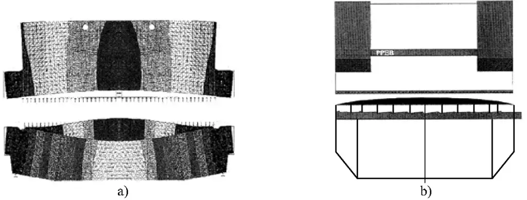
Particularly during the bending process of long pieces, the slider deforms due to insufficient rigidity in the length direction of the bending machine and the layout of the hydraulic cylinders, resulting in different bending angles at the middle and ends. For this reason, the bending machine is equipped with a deflection compensation device to compensate during bending (Figure 3-117).
V. Bending Forming Dies
1. Structure of Bending Machine Dies
Bending machine dies are categorized into general and specialized types. Specialized dies are designed for particular parts. Most bending operations utilize general dies. The structure of the dies is shown in Figure 3-118.
The three key elements in the design of bending machine dies are: the structural dimensions of the die clamping part (related to the equipment), the shape of the upper die and the angle of the working part, and the width and angle of the lower die’s V-groove.
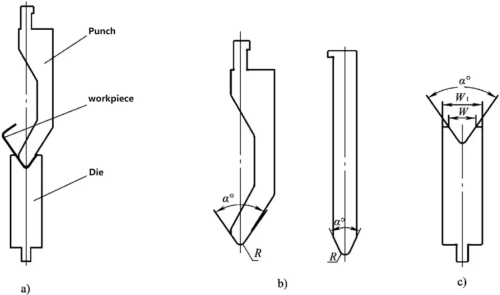
a) Working state of the bending die
b) Structure of the upper die
c) Structure of the lower die
1) As shown in Figure 3-118b, the radius of the rounded corner of the working part of the upper bending die is designed according to the requirements of the bent workpiece. The angle is designed based on the material’s springback and the depth requirement for entering the lower die. The cross-sectional shape of the upper die can be either straight or curved.
2) As depicted in Figure 3-118c, the size of the working part of the lower bending die, denoted as W, is designed based on the sheet thickness and the radius of the rounded corner. The angle is designed according to the material’s springback and the requirement to match the upper die. The angles of the upper and lower dies are identical.
The angles and widths of the V-grooves in bending dies generally have standard values. For materials like carbon steel and aluminum alloy, an angle of 84° is typically used, while for stainless steel, which has a larger springback, the angle is usually less than 75°. The width of the V-groove in the lower die is generally chosen to be eight times the sheet thickness.
After being equipped with dedicated dies, the press brake can form workpieces of some special shapes.
2. Press Brake Die Materials
Press brake die materials typically include 70 steel, 42CrMo, T10, and Cr12MoV, with a heat treatment hardness of over 50 HRC.
VI. Elements of Bending Quality
Cross-sectional dimensional accuracy is one of the main accuracy indicators of a bent part. Many factors can influence this accuracy, including the bending die, blank accuracy, bending sequence, and positioning method.
1. Bending Die
The unfolded dimensions of a bent part are unique. Selecting the correct bending die (upper and lower) is essential to ensure the accuracy of bending dimensions. If not, the required bending precision cannot be guaranteed.
2. Blank Accuracy
Blanks mainly come from shearing, cutting, die punching, or turret punch press operations. Different cutting methods yield different blank accuracies. The cutting process should be chosen based on the accuracy requirements of the bent part to meet the bending precision needs. Besides blank dimensional accuracy, the condition of the blank, such as burrs, side bends, and flatness, will also directly affect the accuracy of the bent part.
3. Bending Sequence
When bending complex shapes, a suitable bending sequence must be chosen to complete the bending formation while ensuring dimensional tolerance requirements.
4. Positioning Method
Positioning is divided into front and side positioning. To ensure bending accuracy, it is best to have one front positioning per meter on the press brake. Some bent parts also require side positioning to improve positioning accuracy.
VII. Production Examples of Bent Forming Parts
1. Bending Formation of Outer Panel Reinforcing Beam
Figure 3-119 shows the workpiece diagram of the outer panel reinforcing beam, made from 0.8mm thick SUS301L-HT stainless steel plate.

As can be seen from the figure, this bent part requires high precision in its dimensions and involves multiple bending operations. If the bending sequence is not properly arranged, the workpiece may interfere with the mold during the bending process, failing to meet the accuracy requirements.
Solution 1: Laser Cutting → Leveling One Bend → Forming.
The bending sequence follows the scheme shown in Figure 3-120. This meets the usage requirements in actual production, thanks to the high precision of laser cutting, the small cumulative error, and the capability to implement multi-point positioning during bending.
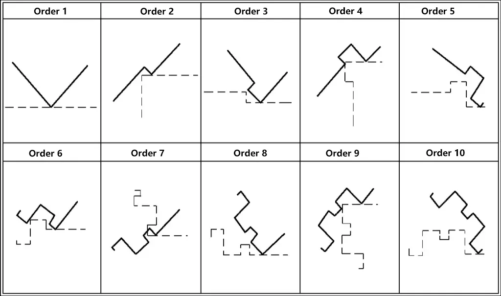
Solution 2: Shearing → Notching → Leveling → Bending → Forming.
Due to the poor precision of shearing, multi-point positioning would affect the bending dimensions of the intermediate bends. In this case, multi-point positioning cannot be used; only a single base point positioning can be applied. Taking the outer panel reinforcing beam as an example, the two outermost bends should be made first.
By leveraging the positioning accuracy of the CNC bending machine, the shearing error is transferred to the outermost sides where precision is not required. Subsequently, the bending of the internal eight bends is performed.
2. Bending Formation of Hat-shaped Beams
Figure 3-121 shows the cross-sectional view of the side pillar bending blank. The workpiece is 3500mm in length, made from 1mm thick SUS301L-HT stainless steel sheet.
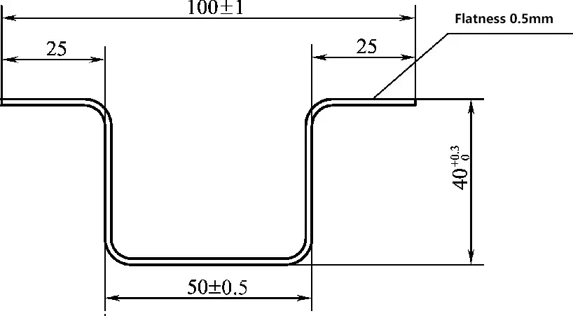
This component requires a high degree of cross-sectional dimensional precision to ensure the quality of the subsequent bending process. Given the need to maintain certain tolerance levels in the cross-sectional dimensions, the bending sequence has been designed as illustrated in Figure 3-122.
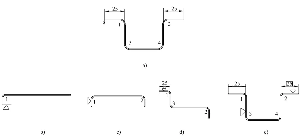
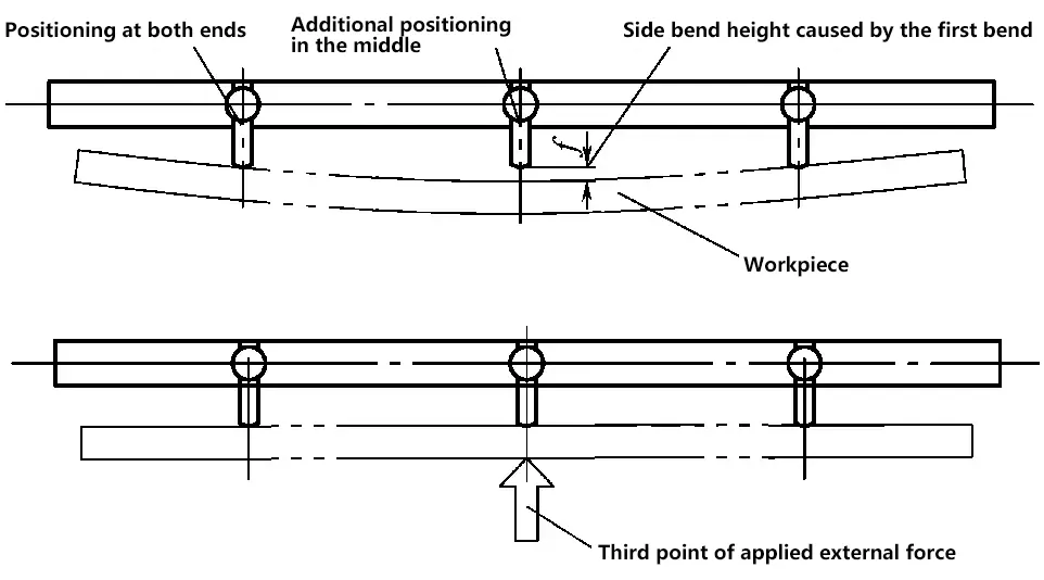
Due to the length of this component, it is prone to side bending during the bending process. This issue is inevitable. Therefore, starting from the second bend, a three-point positioning method must be used for bending (Figure 3-123), i.e., after forcing a straight line positioning at three points on the positioning surface, proceed with the bending.
3. Bending Formation of Angle Iron
Figure 3-124 shows the diagram of the angle iron component, made of 3mm thick weathering steel. It is a simple bending part, but the sides of the bending line are asymmetrical.

Since bending is a free bending process, the bending line may deviate under the action of eccentric force, resulting in the component being nonconforming. To address this, a solution of adding process supplemental material is adopted, as shown in Figure 3-125. The supplemental material is cut off after bending.
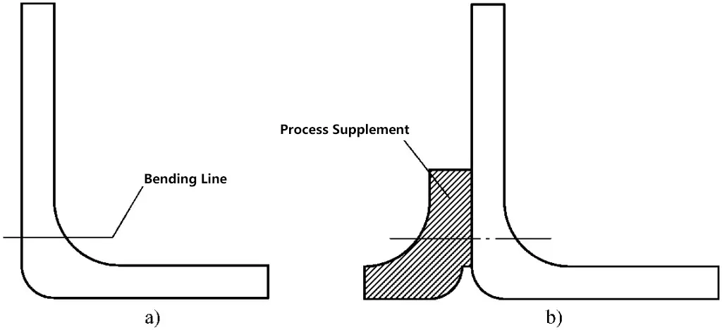
a) The bending lines are asymmetrical on both sides
b) Process supplement material makes it symmetrical
4. Bending Formation of Bogie Cover Plate
Figure 3-126 shows the bogie cover plate, made of 12mm thick S355J2G3 steel plate. Such parts are usually formed at once using a mold. However, if the workpiece is small enough to be lifted manually, using a bending machine for forming is more likely to ensure dimensional accuracy.
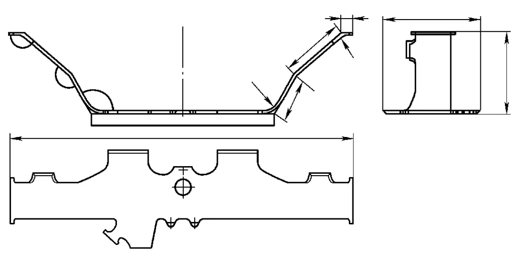
The manufacturing process flow for this component is as follows: Sandblasting the steel plate surface for rust removal → Laser cutting of the raw material → Grinding off the burrs → Processing the bevel → Bending to form.
Figure 3-127 illustrates the bending process, with positioning points at both ends. The positioning method, bending sequence, and bending die are the three primary factors.

1) Positioning Method:
As the bottom cover plate is a long and thin component, a combination of rear and side positioning methods must be used during bending. The rear positioning must be on a horizontal plane to ensure the straightness of the workpiece after bending.
2) Bending Sequence:
For ease of operation and accurate positioning, bending is carried out from the middle towards both ends. The bending sequence is the inner side R100 → R50 → outer side R100. The blank is cut by laser cutting, which has high dimensional accuracy. Both ends are positioned separately, resulting in a smaller cumulative error.
3) Bending Die:
The springback amount of the bending forming is ensured by controlling the travel of the bending machine slider. No measures have been taken to control springback on the die. The structure of the die is shown in Figure 3-128.
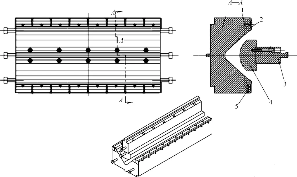
1 – Press Column Seat
2 – Gate Column
3 – Upper Gate Seat
4 – Upper Gate
5 – Lower Gate

