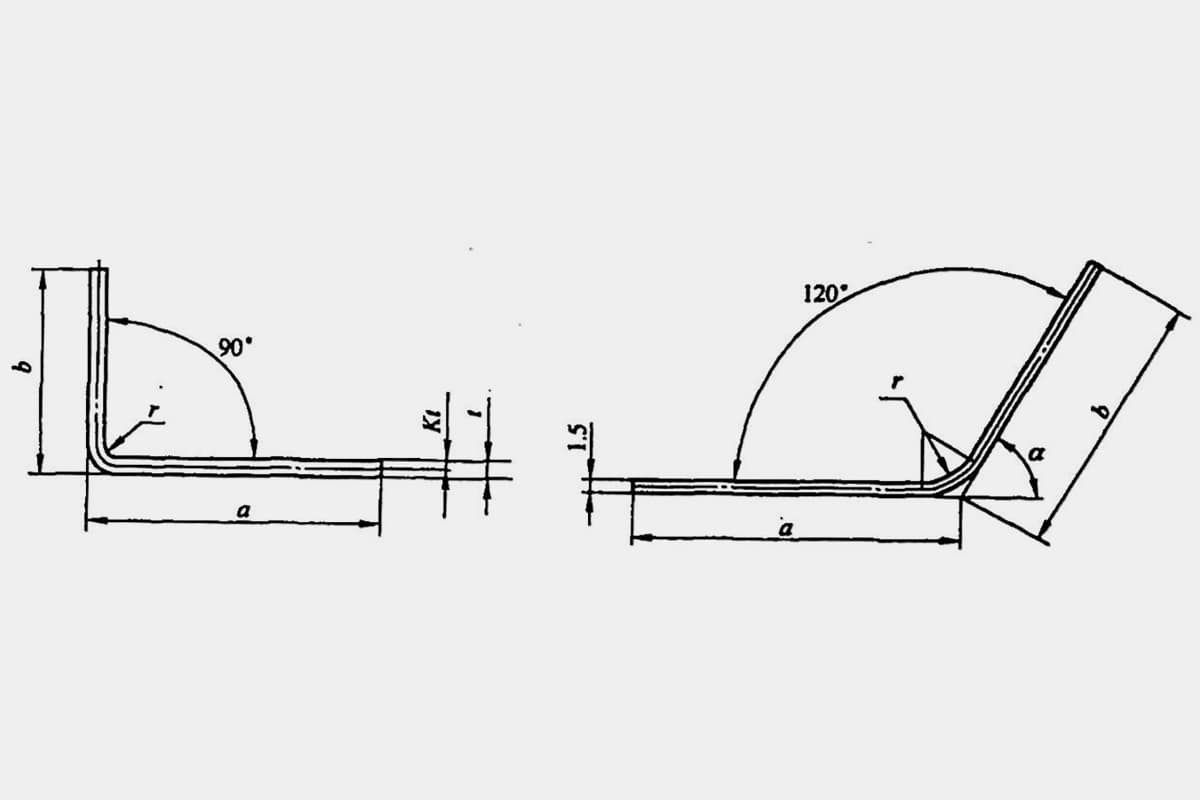
For sheet metal bending parts, calculating the blank size is a prerequisite for formulating the bending process plan. Different technicians may select different bend allowance factors in their process documents, and the accuracy of the blank size directly impacts the dimensional accuracy and product quality of the bending parts.
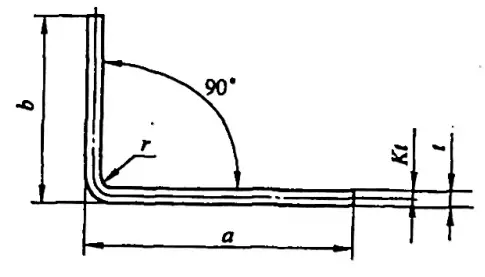
Sometimes, inaccurate calculations can even result in waste products. The unfolded length L of a typical simple bending part (see Figure 5-1) is L = a + b – y (where y is the bending deduction, also known as the correction value for the R part).
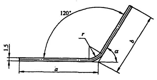
However, in various manuals and materials, the bending deduction for φ=90° can be directly obtained, while for non-90° bends, like shown in Figure 5-2, technicians need to calculate it based on an experience factor (K factor).
Related reading: The Art of Sheet Metal Unfolding Explained
1. Principle of Calculating the Unfolded Dimension of Sheet Metal Bends
The unfolded dimension of a bent blank is determined based on the principle that the length of the neutral layer remains unchanged before and after bending. When the sheet metal is bent, the outer layer fibers of the blank section are stretched, and the inner layer fibers are compressed.
The stretching of the outer layer fibers gradually decreases from the outside to the inside, and the compression of the inner layer fibers also gradually decreases from the inside to the outside.
When the fibers transition from stretching to compression or from compression to stretching, there must be a layer of fibers where the stress and strain are zero, and its length remains unchanged before and after bending.
This layer is what we define as the neutral layer. Therefore, the key to calculating the unfolded dimension of the bent blank is to determine the position of the neutral layer. The position of the neutral layer is determined based on the condition that the volume of the bent part and the blank are equal before and after plastic deformation.
2. Determining the Curvature Radius ρ of the Neutral Layer
In theory, due to the uneven deformation along the thickness direction of the bent part, the neutral layer is a parabolic surface, but for the sake of calculation, it is usually considered as a circular arc surface. When the bending deformation is very small (r/t >6.5), the neutral layer can be approximately considered to be in the middle of the material thickness, that is, the curvature radius of the neutral layer is ρ=r+t/2.
When the deformation is very large (r/t≤6.5), the material thickness will become thinner, and the section distortion is very large, as shown in Figure 5-3.
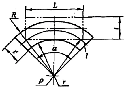
At this time, in order to satisfy the balance condition that the resultant force of all the acting forces in the section is zero, the neutral layer must move towards the inner surface of the material.
At this point, we can determine the curvature radius of the neutral layer based on the condition that the volume does not change during plastic deformation, that is, the volume before bending: V0=LBt, and the volume after bending:
V=(R2-r2)α*B’/2.
In the formula, B is the width of the blank (mm); B’ is the average width of the blank after bending (mm); α is the bending center angle. According to the principle that the volume is equal before and after bending, we have V0=V, that is,
LBt=(R2-r2)α*B’/2, and L=(R2-r2)α*B’/2tB (5-1).
From the zero stress and strain of the neutral layer, we get L=l=αρ, where L is the length before deformation of the neutral layer (mm), and l is the length after deformation of the neutral layer (mm).
Substituting equation (5-1), we get ρ=(R2-r2)B’/2tB. If we substitute R=r+t’ into the above equation, we can get another form of the equation ρ=(r/t+η/2)tβη (5-2), where β is the width factor, β=B’/B, and generally when a wide plate (B>3t) is bent, it is usually considered that β=1; η is the thinning factor, η=t’/t.
Equation (5-2) is the formula for theoretically calculating the position of the neutral layer. When calculating, we must know η, that is, the thinning rule. The value of η can be referred to in Table 5-1.
It should be pointed out that the thinning rule is quite complex, the distribution of the neutral layer’s position in the bending area is not uniform, and the thinning rule is also related to many factors such as the bending method, the width of the bending lower die slot and the material thickness.
This brings unavoidable errors to the theoretical calculation of the position of the neutral layer, thus reducing the practical application value of the theoretical determination method.
Table 5-1: Thinning factor η
| r/t | 0.1 | 0.25 | 0.5 | 1.0 | 2.0 | 3.0 | 4.0 | 5.0 | ≥5 |
| η | 0.82 | 0.87 | 0.92 | 0.96 | 0.985 | 0.992 | 0.995 | 0.998 | 1 |
In actual production, an empirical formula, which is more straightforward than theoretical computation, is typically used to determine the position of the neutral axis, as follows:
ρ = r + Kt (5-3)
Where:
- ρ – Radius of curvature of the neutral axis (mm)
- r – Inside radius of bending of the raw material (mm)
- t – Material thickness (mm)
- K – Neutral axis coefficient (empirical K factor), refer to Table 5-2
Table 5-2: Empirical values of the neutral axis coefficient K
| r/t | K1 | K2 | ±k |
| 0.3 | 0.2 | 0.23 | 0.04 |
| 0.4 | 0.22 | 0.24 | |
| 0.5 | 0.23 | 0.25 | |
| 0.6 | 0.24 | 0.265 | |
| 0.7 | 0.26 | 0.28 | |
| 0.8 | 0.28 | 0.3 | |
| 1 | 0.31 | 0.32 | |
| 1.2 | 0.32 | 0.33 | |
| 1.3 | 0.33 | 0.34 | |
| 1.5 | 0.35 | 0.36 | |
| 2 | 0.37 | 0.38 | 0.03 |
| 2.5 | 0.38 | 0.39 | |
| 3 | 0.39 | 0.4 | |
| 4 | 0.42 | 0.42 | |
| 5 | 0.44 | 0.44 | 0.02 |
| 6 | 0.46 | 0.46 | |
| 7 | 0.48 | 0.48 | |
| ≥8 | 0.5 | 0.5 |
Note:
- K1 is applicable to V-shaped or U-shaped bends with a top plate or press plate.
- K2 is suitable for V-shaped bends without a top plate.
3. Calculation of Blank Unfolded Dimensions for Several Typical Sheet Metal Bends
Based on the definition of the neutral layer, the blank unfolded dimension should be equal to the length of the neutral layer. Typically, based on the inner bend radius r of the blank, bends are categorized as round-cornered and non-round-cornered bends: bends are considered round-cornered when r>0.5t, and non-round-cornered when r<0.5t.
Furthermore, based on the plate width B, bends are categorized into wide and narrow plate bends: when the plate width B>3t, it’s referred to as a wide plate bend, and when the plate width B<3t, it’s referred to as a narrow plate bend.
In production practice, bends with a round-corner radius (r>0.5t) and wide plates (B>3t) are the most widely used, and considering the universality of bends, we mainly discuss the calculation of blank unfolded dimensions for bends with round-corner radius and wide plates during bending.
3.1 Calculation of Blank Unfolded Dimensions for Round-Corner Bends (r>0.5t)
When r>0.5t, B>3t, due to the thinning of the bending part is not severe and the cross-sectional distortion is small, the length of the blank can be determined based on the principle that the length of the neutral layer is equal to the blank unfolded dimension.
The common methods for calculating the blank unfolded dimensions of round-corner bends (r>0.5t) are divided into: the calculation of the bending coefficient and the calculation of the bending deduction value.
1. Round-Corner Bends (r>0.5t) Bending Coefficient Calculation for Blank Unfolded Dimensions:
1) The bending coefficient is the length of the arc part measured along the neutral layer of the bending deformation zone (bending R part), as shown in Figure 5-4.
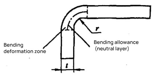
The bending coefficient is calculated by formula (5-4): x=παρ/180° (5-4)
Where ρ is the radius of curvature of the neutral layer (mm).
2) Figure 5-5 shows an example of dimension notation for the bending coefficient calculation of blank unfolded dimensions, and its formula for calculating the bending coefficient of blank unfolded dimensions is as follows.

a) φ > 90° b) φ≤90
L=a+b+x (5-5)
By substituting equation (5-3) into equation (5-4), we obtain the formula for the bending coefficient:
x=πα(r+Kt)/180° (5-6)
By substituting equation (5-6) into equation (5-5), we obtain the formula for calculating the unfolded size of the bent blank:
L=a+b+πα(r+Kt)/180° (5-7)
Where:
- L – The unfolded size of the blank (mm);
- K – Coefficient for the K-factor, refer to Table 5-2 for its value;
- α – The central angle of bending, its relationship with the angle of the bent part is α=180°-φ;
- r – The bending radius of the inner layer of the blank (mm);
- t – The thickness of the material (mm);
- a, b – The lengths of the straight parts of the component (mm), respectively.
2. Calculation of the bending deduction for unfolded size of a rounded corner bent part (r>0.5t)
1) The bending deduction (also known as the correction value for the R part) is the difference between twice the R of the bending deformation zone (the R part of the bend) and the bending coefficient, as shown in Figure 5-6.

The bending deduction (correction value for the R part) is calculated as per equation (5-8):
y = 2R-παr/180° (5-8)
2) Figure 5-7 shows an example of dimension annotation for the calculation of bending deduction for the unfolded size of the blank. The bending deduction y is calculated by the following formula:

a)90°<φ≤165° b)φ≤90°
①When φ ≤ 90°:
R=(r+t)/tan(φ/2)
Substituting the above formula and formula (5-3) into formula (5-8), we obtain the bending deduction (i.e., the correction value of the R part) for a bend φ≤90° (see Figure 5-7b):
y=2(r+t)/tan(φ/2)-πα(r+Kt)/180° (5-9)
②When 90°<φ≤165°:
R=(r+t)tan[(180°-φ)/2]
Substituting the above formula and formula (5-3) into formula (5-8), we obtain the bending deduction (i.e., the correction value of the R part) for a bend 90°<φ≤165° (see Figure 5-7a):
y=2(r+t)tan[(180°-φ)/2]-πα(r+Kt)/180° (5-10)
③When 165°<φ≤180°:
y≈0
3) The formula for calculating the bending deduction value of the blank size of the part shown in Figure 5-7 is:
L=a+b-y (5-11)
①When φ≤90°, substituting formula (5-9) into formula (5-11), we obtain the formula for calculating the bending deduction value of the blank size as follows:
L=a+b-[2(r+t)/tan(φ/2)-πα(r+Kt)/180°] (5-12)
②When 90°<φ≤165°, substituting formula (5-10) into formula (5-11), we obtain the formula for calculating the bending deduction value of the blank size as follows:
L=a+b-[2(r+t)tan[(180°-φ)/2]-πα(r+Kt)/180°] (5-13)
③When 165°<φ≤180°:
L≈a+b (5-14)
Where,
- y – Bending deduction (mm)
- L – Blank size of the part (mm)
- r – Inner bending radius of the blank (mm)
- t – Material thickness (mm)
- α – Bending center angle, its relation with the bend angle is α=180°-φ
- a, b—Edge lengths of the part (mm) to the bending vertex.
3. Calculation of the blank size for multi-angle bends
For multi-angle bends, the blank size is the sum of the R part and the lengths of the straight edges.
1) Multi-angle bend blank size calculation by the bending coefficient:
L=l1+l2+…+ln+1+nx (5-15)
Where l1, l2…ln+1 are the lengths of the straight parts of each edge of the part (mm);
n is the number of bends R.
2) Multi-angle bend blank size calculation by the bending deduction:
L=l1+l2+…+ln+1-ny (5-16)
Where l1, l2…ln+1 are the lengths of the edges of the part (mm) to the bending vertex;
n is the number of bends R.
Example 5-1: Calculate the blank size for the bend shown in Figure 5-8.
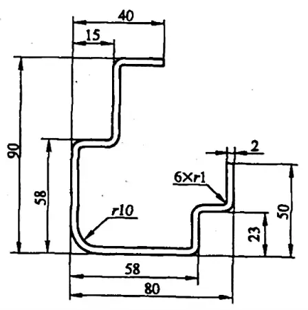
Solution 1: Calculate the blank size using the bending coefficient.
Refer to Appendix A: When the bending piece angle φ=90°, thickness t=2mm, and radius r=10mm, the bending coefficient is 2.68mm;
When the bending piece angle is 90°, thickness t=2mm, and radius r=10mm, the bending coefficient is x2=16.9mm.
From equations (5-5) and (5-15), the flat size of the blank for the bent piece is calculated as:
L= [(40-15-2-1) + (90-58-2-2×1) + (15-2-2×1) +2(58-2×2-10-1) + (23-2-2×1) + (80-58-2-2×1) + (50-23-2-1) + 6×2.68 + 16.9]mm
= (22+28+11+86+19+18+24+16.08+16.9)mm
= 240.98mm.
Solution 2: Calculate the flat size of the blank using the bending deduction value.
Refer to Appendix C: For a bend with an angle φ=90°, thickness t=2mm, and radius r=1mm, the correction value for the R section is y1=3.32mm; for a bend with an angle φ=90°, thickness t=2mm, and radius r=10mm, the correction value for the R section is y2=7.1mm.
The raw size of the bent part can be obtained from equations (5-11) and (5-16):
L= [(40-15) + (90-58+2) + (15+2) + 2×58 + (23+2) + (80-58+2) + (50-23) – 6×3.32 – 7.1] mm
= (25+34+17+116+25+24+27-19.92-7.1) mm
= 240.98 mm
Example 5-2: Compute the raw size of the bent part shown in Figure 5-9.
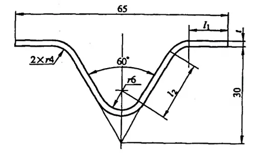
Solution: Calculate the raw size using the bending coefficient.
The formula for calculating the blank dimensions of the bent part from equations (5-5) and (5-15) is:
L=2l1+2l2+2x1+x2
where l1 = [32.5 – (30tan30°+4tan30°)] mm = 12.87 mm
and l2 = [(30/cos30°) – (8/tan30°+4tan30°)] mm = 18.47 mm
Referencing Appendix A: when the bend angle φ=120°, t=2mm, r=4mm, the bending factor value is x1=4.98mm; when the bend angle φ=60°, t=2mm, r=6mm, the bending factor value is x2=14.16mm.
Substituting these values into the formula gives the blank unfolded length as L= (2×12.87 + 2×18.47 + 2×4.98 + 14.16) mm = 86.8 mm.
It should be noted that for simpler bends with lower precision requirements, the blank unfolded dimensions can be directly calculated. However, for more complex bends or those with higher precision requirements, the shape and dimensions of the unfolded blank need to be repeatedly tested and continually revised to confirm the shape and dimensions of the blank.
3.2 Calculation of Blank Development Dimensions for Sharp Bend Components (r<0.5t)
When the bend radius r of a component is less than 0.5t, it is referred to as a sharp bend. The calculation of the blank development dimension for such components is based on the principle of volume consistency before and after bending.
With sharp bends, due to severe thinning of the material at the bend, the deformation process is extremely complex, making it difficult to accurately calculate the blank development dimensions. Therefore, the calculated blank development dimensions need to be corrected based on empirical data or through trial bending.
The calculation formula for the blank development dimensions of sharp bend components (r<0.5t, φ=90°) can be found in Table 5-3.
Table 5-3 Calculation formula for blank development dimensions of sharp bend components (r<0.5t, φ=90°) (unit: mm)
| Serial Number | Bending Features | Schematic | Formula |
| 1 | Bend a corner. |  | L=a+b+0.4t |
| 2 | Flatten it. |  | L=a+b-0.43t |
| 3 | Bend two corners at once. |  | L=a+b+c+0.6t |
| 4 | Bend three corners simultaneously. |  | L=a+b+c+d+0.75t |
| 5 | Bend two corners in the first instance, and bend another corner in the second. | L=a+b+c+d+t | |
| 6 | Bend four corners at the same time. |  | L=a+2b+2c+1.2t |
| 7 | Bend to form four corners in two instances. | L=a+2b+2c+1.2t |
3.3 Calculation of the Unfolded Dimensions for Hinge-type Bending Parts
For hinge-type bending parts with r= (0.6~3.5)t (refer to Figure 5-10), the flanging process usually follows the pattern shown in Figure 5-11. During flanging, the thickness of the sheet metal increases and the neutral layer shifts outward. The unfolded dimensions of the blank can be approximatively calculated by the following formula:
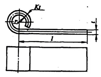
- a) First operation
- b) Second operation
L=l+1.57π(r+Kt)+r
Where:
- L – Unfolded dimensions of the blank (mm);
- l – Length of the straight segment (mm);
- r – Internal bending radius of the blank (mm);
- K – Displacement coefficient of the neutral layer. When r/t=0.5~1.8, K is usually taken as 0.5~0.70 (the smaller the r/t value, the larger the K value; conversely, the smaller the K value). It can also be selected according to Table 5-4.
Table 5-4 Displacement Coefficient of Neutral Layer for Hinge-type Bending Parts
| r/t | ≥0.5~0.6 | >0.6~0.8 | >0.8~1 | >1~1.2 | >1.2~1.5 | >1.5~1.8 | >1.8~2 | >2~2.2 | >2.2 |
| K | 0.76 | 0.73 | 0.7 | 0.67 | 0.64 | 0.61 | 0.58 | 0.54 | 0.5 |

