Hydraulic Press Brake vs. Folding Machine: A Comprehensive Guide
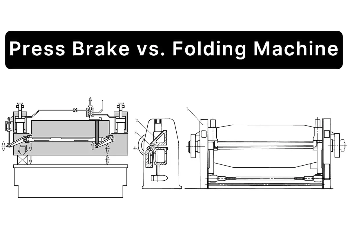
I. Overview 1. Process Introduction and Drive Mode The press brake is a processing machinery that bends metal sheets into [...]

In the manufacturing process, sheet metal bending often encounters various quality issues, affecting the enhancement of production efficiency and the stability of product quality.
This article discusses common bending and cutting quality issues encountered in production practice, analyzes the causes of these issues, and proposes solutions to provide experience and reference for similar problems that may arise in subsequent production practices.
Sheet metal bending involves using a CNC bending machine equipped with standard (or specialized) dies to bend metal sheets into various required geometric cross-sectional shapes.
The rationality of the bending process directly affects the final dimensions and appearance of the product. Choosing the right bending dies is crucial for the final shape of the product.
In actual production, due to the uncertainty of product dimensions and the diversity of product types, we often encounter issues like dimensional interference and mismatched die angles during cold working of parts, which pose significant challenges.
Bending quality is influenced by factors such as product size, shape, material, dies, equipment, and auxiliary facilities, leading to various quality issues that impact production efficiency and product quality stability. Therefore, resolving and preventing these quality issues is particularly important.
This article summarizes and describes common sheet metal bending quality issues encountered in production practice, analyzes their causes based on production experience, and proposes solutions.
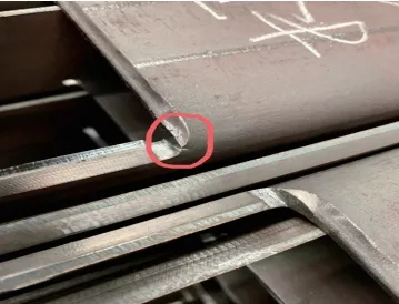
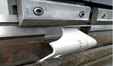
Bending cracking refers to the phenomenon where burrs or fine cracks often appear at the edges of materials after cutting, shearing, or stamping, leading to stress concentration and cracking when bent. An example is the cracking at the corners of the U-shaped reinforcement groove (2A90100185G00) of the HXD1C locomotive accessory after bending, as shown in Figure 1.
The main causes of bending cracking include:
In the manufacturing process, the bending cracking phenomenon needs to be addressed according to specific circumstances. For the bending cracking issue shown in Figure 1, solutions such as adding process holes or grooves can be employed, as illustrated in Figure 2.
Bending interference primarily occurs in products undergoing secondary or higher-order bending, where the bending edge collides with the die or equipment, preventing normal formation. Bending interference is mainly influenced by the part’s shape, size, and die, and is caused by the design structure of the bent part, the chosen bending sequence, and the selected bending dies.
The solutions include:
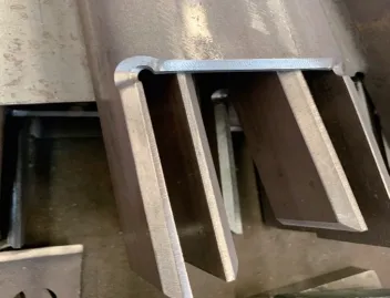
For example, the installation bracket for the cable tray of Shanghai’s Line 18 chassis attachment (ADC1027252G030) is a U-shaped channel steel with a mid-width of 100mm, side height of 80mm, and bending radius of 15mm. Using existing workshop dies for a simulation bend resulted in bending interference.
To address this interference, a part of the bending upper die was mechanically modified (as shown in Figure 3). A 140mm×48mm notch was cut in the middle line of the existing R15mm straight blade upper die (L=800mm) (as seen in Figure 4).
The notch’s position was determined based on the simulated bending interference location, without affecting its original function. This modification of the bending die successfully resolved the bending interference issue.

Bending indentation occurs when the sheet metal progressively presses against the inner surface of the die’s V-shaped groove during bending, creating friction that leaves noticeable marks on the material’s surface.
For parts with high surface requirements, traditional bending cannot meet the quality demands, and the bending indentation (as shown in Figure 5) does not satisfy the requirements of the subsequent process.

Bending indentation is mainly influenced by the hardness of the sheet material and the structure of the lower die. The harder the material, the greater its resistance to plastic deformation, making it more difficult for the material to deform and easier for indentations to form.
The likelihood of bending indentation occurring in common materials is in the following order: Aluminum > Carbon Steel > Stainless Steel. The wider the opening of the lower die, the broader and shallower the indentation. The larger the R size of the die’s shoulder, the shallower the indentation depth.
To resolve bending indentation issues, apart from improving material hardness and modifying the lower die structure, methods like using anti-indentation rubber pads and ball-bearing lower dies can be employed.
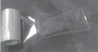
Anti-indentation rubber pads reduce indentation formation through physical isolation, as shown in Figure 6. Ball-bearing lower dies convert the compressive friction required for traditional die forming into rolling friction, reducing friction and minimizing damage to the product, as illustrated in Figure 7.

During bending, materials undergo both plastic and elastic deformation. Once the workpiece is removed from the bending die, it experiences elastic recovery, causing its shape and size to differ from those during loading. This phenomenon is known as bending springback and is one of the main reasons for inadequate bending angles.
Factors influencing springback include the mechanical properties of the sheet material and the conditions of bending deformation. The magnitude of springback is directly proportional to the yield strength of the sheet and inversely proportional to its elastic modulus.
The smaller the relative bending radius (the ratio of the bending radius to the sheet thickness, R/t), the lesser the springback. The shape of the bent part also affects the magnitude of springback; typically, U-shaped parts have less springback than V-shaped parts.
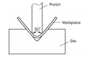
The main method to overcome bending springback is angle compensation. This is usually achieved by designing the bending die with a slope equal to the angle of springback, effectively balancing the effects of springback. As shown in Figure 8, using a bending die with an 80° slope can successfully bend a workpiece to a 90° angle.
Given the multitude of factors affecting bending springback, accurately calculating its value is extremely challenging. Through trial adjustments and experience accumulation, mastering the pattern of springback and applying appropriate compensation, along with measures in die structure, are effective methods to ensure product quality.
Bending slippage refers to the phenomenon where the workpiece to be bent lacks complete and effective support points on the lower die groove, leading to the workpiece easily slipping and failing to be positioned correctly for bending.
The main causes of bending slippage are as follows:
1) The width of the lower bending die is too large, causing slippage when the bending size is less than half the width of the lower die.
2) The shape and size of the workpiece affect positioning, resulting in bending slippage when the workpiece has too short a side for die positioning or lacks an effective positioning edge.
There are mainly two methods to solve bending slippage:
1) Method 1. Select an appropriate lower bending die, generally choosing a die width of 4 to 6 times the sheet thickness for bending.
2) Method 2. Address bending slippage issues caused by poor positioning during bending by adding templates or process edges.
Generally, bending is positioned along one straight edge of the workpiece, requiring contact with two end faces of the bending die for positioning. However, in actual production, there are cases where the product’s edge for die positioning is too short or non-existent, making bending positioning impossible.
Solutions include:
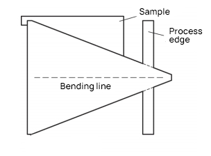
a) For sheet thickness t ≤ 6mm, add process edges for positioning. The process edge should extend flush with the end edge of the part, and the junction can be cut with a laser slit for easy grinding and removal after bending.
b) For sheet thickness t > 6mm, use cut templates for positioning. The thickness of the template can be equal to or slightly less than the thickness of the workpiece. As shown in Figure 9, both positioning methods can solve the bending slippage issue.
In the manufacturing process, it’s common to encounter workpieces requiring a large bending radius for which the workshop lacks matching large-radius dies. In such cases, fabricating an integral forming die or large-radius die can be time-consuming and costly. Instead, using a small-radius multi-bend forming process is more cost-effective and versatile.
For example, the Superbus 2.0 project’s component, Vertical Plate 3 (ADC1043361G030), requires a bending radius of 125mm and a bending angle of 90°, as shown in Figure 10. Without a corresponding bending die in the workshop, a multi-bend process can be applied.
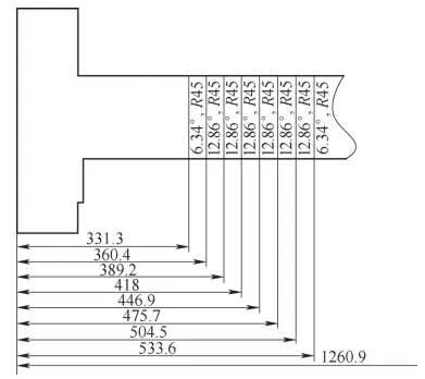
First, the R125mm position is modeled in 3D software for layout bending, then the software automatically unfolds the flat two-dimensional drawing. By entering a 45mm bending radius into the software and comparing multiple sets of data, it’s confirmed that forming by bending 8 times can ensure the arc section.
Subsequently, the bending data for each cut (bending angle, bending line position length) are generated, as shown in Figure 11. Finally, the bending data is used for on-site trial bending, as shown in Figure 12.


Bending bulge occurs when sheet metal, after bending, exhibits protrusion on both sides of the bend due to material compression, leading to a width larger than the original size. The size of the bending bulge generally relates to the thickness of the part and the bending radius; the thicker the material and the smaller the radius, the more pronounced the bulge.
To prevent this issue, process notches can be added on both sides of the bending line in the bending expansion drawing stage, as shown in Figure 13. These notches are typically in the form of an arc, with a diameter generally more than 1.5 times the thickness of the workpiece, effectively counteracting the bending bulge. For workpieces that have already developed a bending bulge, manual grinding is usually employed for correction.

It should be noted that the common bending and cutting quality issues listed above do not consider the impacts of human or equipment factors (such as errors in unfolding dimensions, incorrect selection of bending parameters, and equipment aging).
In production practice, it’s crucial to select appropriate bending process parameters based on equipment performance, product size, and material characteristics, and to strictly follow operating norms.
It’s not only necessary to consider factors such as project progress, cost, and quality comprehensively and adopt suitable methods to solve bending quality issues, but also to preemptively identify and prevent potential bending problems through the accumulation of experience and foresight in process analysis.
This article lists several common bending quality issues and their solutions, hoping to provide some reference and guidance for industry colleagues.