The development of CNC cutting technology has been rapid in recent years. With its flexibility and process compounding, it is replacing mold punching methods and occupies a very significant position in the processing of stamping parts for rail passenger cars.
The widely used types include CNC laser cutting, CNC plasma cutting, CNC flame cutting, and CNC high-pressure water jet cutting. The materials cut include carbon steel plates, stainless steel plates, and aluminum alloy plates.
CNC Laser Cutting Technology
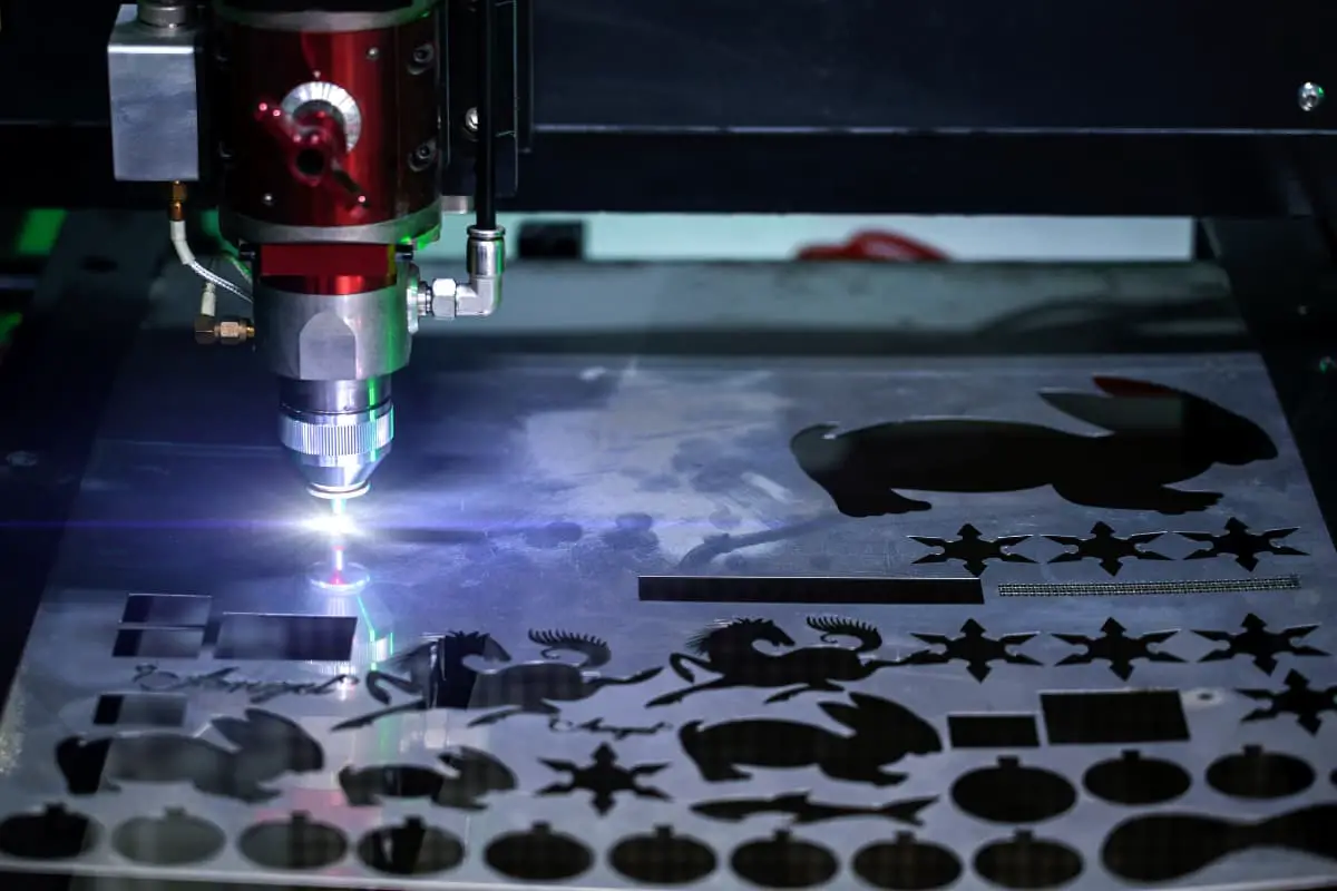
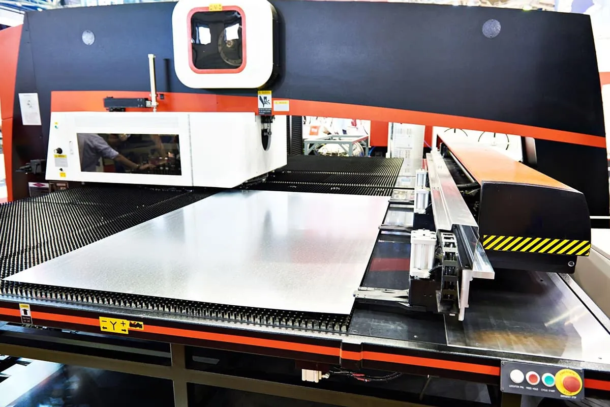
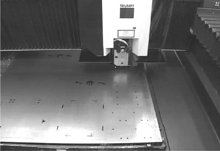
Laser cutting is an advanced processing method that uses a high-energy laser beam to thermally cut materials. It can cut various metals and non-metal sheets and is widely used in the manufacture of rail passenger cars. Figure 3-47 shows a picture of laser-cut sheet metal.
(1) Principle of Laser Cutting
Laser cutting involves irradiating the workpiece with a focused high-energy laser beam, causing it to rapidly melt, vaporize, ablate, or reach its ignition point. At the same time, the molten material is blown away by a high-speed airflow coaxial with the beam, cutting the workpiece. Laser cutting is one of the thermal cutting methods.
(2) Characteristics of Laser Cutting
1) The cut is narrow, ranging from 0.15~0.4mm (depending on the thickness of the plate), and it is vertical to the surface.
The cut surface is smooth and beautiful, the heat-affected zone is small, the workpiece deformation is small, the cutting precision is high, and the dimensional accuracy of the cut parts can reach ±0.05mm, making high material utilization possible.
2) Generally equipped with an exchange worktable, continuous cutting can be achieved during the cutting process. The cutting speed is fast, reaching up to 70m/min. It is a non-contact cutting process, can cut parts of different shapes, and produces low noise and little pollution during the process.
3) The quality of cutting thin sheet material is good, the speed is fast, but as the thickness of the sheet increases, the cutting speed significantly decreases, and the quality of the cut section also decreases.
(3) Application of Laser Cutting in the Field of Rail Passenger Cars
In the manufacture of rail passenger cars, laser cutting technology is mainly used for blanking carbon steel plates with a thickness of less than 16mm and stainless steel plates with a thickness of less than 12mm. Among all blanking technologies, it has the highest efficiency and best precision.
CNC Plasma Arc Cutting Technology
Plasma arc cutting uses a high-energy plasma arc and high-speed plasma flow to blow molten metal away from the cut, forming a continuous kerf. With its fast cutting speed and minimal workpiece deformation, plasma arc cutting is suitable for cutting a variety of metal materials.
(1) Common Plasma Arc Cutting Methods
There are two main methods: air plasma arc cutting and precision plasma arc cutting.
1) Air Plasma Arc Cutting: This is a manual plasma arc cutting technique, primarily used for intermediate processes in carbon steel, stainless steel, and aluminum alloy stampings, such as hole cutting, slot cutting, edge cutting, head cutting, and seam cutting.
2) Precision Plasma Arc Cutting: This is a CNC cutting technique that can cut materials such as carbon steel and stainless steel with a thickness less than 30mm.
(2) Precision Plasma Arc Cutting Process
This process is suitable for all metals and some non-metal materials. It’s an effective method for cutting stainless steel, aluminum and aluminum alloys, copper and copper alloys, and other non-ferrous metals. The maximum cutting thickness can reach 180-200mm.
Currently, in passenger car production, it is used to cut carbon steel with a thickness of 5-25mm and stainless steel with a thickness of 4-20mm.
(3) Plasma Arc Cutting Process Parameters
These include cutting current, cutting voltage, cutting speed, gas flow, and the height of the nozzle from the workpiece.
1) The cutting current and voltage determine the power of the plasma arc. As the power of the plasma arc increases, both the cutting speed and cutting thickness can correspondingly increase.
Cutting current is typically selected based on the thickness of the plate and the cutting speed. Too high a cutting current can easily burn the electrode and nozzle, producing a double arc and forming a V-shaped kerf.
2) A higher cutting voltage is beneficial for cutting thick plates, and the cutting effect is better. Although increasing the current can increase cutting thickness and speed, merely increasing the current will cause the arc column to thicken, widening the kerf.
3) Cutting speed is a major indicator of cutting productivity, and it significantly impacts cutting quality. The appropriate cutting speed is crucial for a flat kerf surface. Cutting speed depends on material thickness, cutting current, types and flow of gas, nozzle structure, etc. At the same power, increasing the cutting speed will cause the kerf to slant.
4) The gas flow should match the nozzle aperture. Appropriately increasing the gas flow can strengthen the thermal compression effect of the arc, making the plasma arc more concentrated. The cutting voltage will increase accordingly, benefiting the enhancement of cutting capability and quality.
5) The height of the nozzle from the workpiece is generally 6-8mm. For air plasma and water-compressed plasma arcs, the height of the nozzle from the workpiece can be slightly less than 6-8mm.
When the cutting distance increases, the length of the plasma arc column exposed in space increases, leading to a decrease in effective heat and an increased likelihood of a double arc. If the distance is too small, the nozzle can easily short-circuit with the workpiece and burn, disrupting the normal cutting process.
Tables 3-64 and 3-65 provide parameters for low carbon steel and stainless steel cutting with HiFoucs100 precision plasma arc cutting, respectively.
(4) Plasma Arc Cutting Quality
The quality of the cut is mainly evaluated based on the kerf width, kerf perpendicularity, kerf surface roughness, striation depth, bottom dross of the kerf, and the hardness and width of the heat-affected zone of the kerf.
The standards for a good cut are a narrow width, a rectangular cross-section, a smooth surface with no slag or hanging slag, and a surface hardness that does not hinder mechanical processing after cutting.
Table 3-64: HiFoucs100 Fine Plasma Arc Cutting Parameters for Low Carbon Steel
| Plate Thickness/mm | Current/A | Nozzle Model | Diameter/mm | Cutting Gas (Air/bar) | Cutting Gas (O2/bar) | Swirling Gas (O2/bar) | Swirling Gas (N2/bar) | Piercing Delay/s | Torch Spacing/mm | Ignition Height/mm | Arc Voltage/V | Cutting Speed/(m/min) | Kerf Width/mm |
| 2 | 120 | Z2112 | 3 | 6/20 | 6/60 | 6/10 | 6/70 | 0.1 | 2 | 4 | 116 | 7 | 1.9 |
| 3 | 130 | Z2114 | 3 | 6/20 | 6/60 | 6/10 | 6/70 | 0.1 | 2 | 4 | 111 | 6 | 1.8 |
| 6 | 80 | Z2112 | 3 | 6/40 | 6/70 | 6/10 | 6/70 | 0.1 | 2.5 | 4 | 128 | 1.6 | 1.8 |
| 6 | 115 | Z2114 | 4 | 6/40 | 6/70 | 6/10 | 6/70 | 0.1 | 2.5 | 4 | 119 | 2.5 | 2 |
| 8 | 130 | Z2114 | 4 | 6/40 | 6/70 | 6/20 | 6/70 | 0.1 | 3 | 5 | 125 | 2.45 – 2.7 | 2.2 |
| 10 | 130 | Z2114 | 4 | 6/40 | 6/70 | 6/10 | 6/75 | 0.3 | 3 | 5 | 127 | 2.2 – 2.4 | 2.4 |
| 12 | 130 | Z2114 | 4 | 6/40 | 6/70 | 6/10 | 6/75 | 0.4 | 3 | 5 | 128 | 1.8 – 2 | 2.5 |
| 16 | 130 | Z2114 | 4 | 6/40 | 6/75 | 6/10 | 6/75 | 0.4 | 3 | 5 | 132 | 1.4 | 2.7 |
| 18 | 130 | Z2114 | 4 | 6/40 | 6/60 | 6/20 | 6/85 | 0.5 | 3 | 5 | 136 | 0.8 – 1.2 | 2.8 |
| 20 | 130 | Z2114 | 4 | 6/40 | 6/80 | 6/20 | 6/85 | 0.6 | 4 | 6 | 138 | 0.7 – 1.1 | 3 |
| 25 | 130 | Z2114 | 4 | 6/40 | 6/80 | 6/20 | 6/85 | 0.7 | 4 | 6 | 140 | 0.7 – 0.8 | 3.4 |
Table 3-65: HiFoucs100 Fine Plasma Arc Cutting Parameters for Stainless Steel
| Plate Thickness/mm | Current/A | Nozzle Model | Diameter/mm | Cutting Gas Air/bar | Cutting Gas O2/bar | Swirl Gas O2/bar | Swirl Gas N2/bar | Pierce Delay/s | Torch Spacing/mm | Ignition Height/mm | Arc Voltage/V | Cutting Speed/(m/min) | Kerf Width/mm |
| 1 | 30 | Z2007 | 2 | 6/10 | 6/45 | 6/100 | 6/100 | 0 | 2.5 | 3 | 119 | 4.5 | 0.9 |
| 2 | 45 | Z2008 | 2 | 6/10 | 6/40 | 6/100 | 6/60 | 0.1 | 2 | 3 | 125 | 3.2 | 1.1 |
| 3 | 45 | Z2008 | 2 | 5/10 | 5/40 | 5/70 | 5/55 | 0.1 | 2 | 3 | 115 | 2.4 | 1.1 |
| 4 | 50 | Z2008 | 2 | 5/10 | 5/45 | 5/75 | 5/60 | 0.1 | 2 | 3.2 | 116 | 2 | 1.3 |
| 5 | 50 | Z2008 | 2 | 5/10 | 5/45 | 5/80 | 5/60 | 0.1 | 2 | 3.2 | 116 | 1.8 | 1.3 |
| 6 | 50 | Z2008 | 2 | 5/10 | 5/45 | 5/90 | 5/50 | 0.2 | 3 | 4 | 117 | 1.5 | 1.5 |
CNC Flame Cutting Technology
(1) Principle of Flame Cutting
Flame cutting refers to a thermal cutting process that utilizes the heat from a combustible gas and oxygen flame along with cutting oxygen. The heat emitted by the flame causes the cutting oxygen to continually burn, melting the metal.
The molten metal and oxides produced are blown away by the kinetic energy generated by the cutting oxygen flame, forming a cut.
(2) Types of Flame Cutting
The main types include manual cutting, semi-automatic cutting, and CNC flame cutting.
(3) Application of Flame Cutting
Primarily used for cutting carbon steel plates, it is not suitable for cutting stainless steel plates. Manual cutting is used for post-cutting of profiles and formed parts, and for cutting simple shapes and workpieces with low quality requirements.
Semi-automatic cutting is used for cutting thick plate rectangular small parts. CNC flame cutting is applicable for cutting complex-shaped parts.
(4) Flame Cutting Process Parameters
These include preheat flame power, oxygen pressure, cutting speed, nozzle-to-workpiece distance, and cutting angle.
1) The preheating flame power is a critical process parameter that impacts the quality of flame cutting.
Generally, a neutral flame or a slightly oxidizing flame should be chosen for cutting, and the intensity of the flame should be moderate. The preheating flame should be selected based on the thickness of the workpiece, the type of cutting nozzle, and the quality requirements of the workpiece.
The preheating flame power should increase with the thickness of the plate. The relationship between the oxy-acetylene preheating flame power and the cutting plate thickness is shown in Table 3-66.
Table 3-66: Relationship between Oxy-Acetylene Preheating Flame Power and Cutting Plate Thickness
| Plate Thickness/mm | 3~25 | 25~50 | 50~100 | 100~200 | 200~300 |
| Flame Power (Acetylene Consumption) L/min-1 | 4~8.3 | 9.2~12.5 | 12.5~16.7 | 16.7~20 | 20~21.7 |
2) The cutting oxygen pressure depends on the type of cutting nozzle and its size, and the oxygen pressure can be chosen based on the thickness of the workpiece. The recommended values are shown in Table 3-67.
If the cutting oxygen pressure is too high, the cut will become wide and rough; if the pressure is too low, the cutting process will be slow and may cause slag to stick.
In actual cutting, the optimal cutting oxygen pressure can be determined using the method of releasing the wind line. When the wind line is the clearest and longest, it is the appropriate value, achieving the best cutting effect.
Table 3-67: Recommended Values for Cutting Oxygen Pressure
| Workpiece Thickness/mm | 3~12 | 12~30 | 30~50 | 50~100 | 100~150 | 150~200 | 200~300 |
| Cutting Oxygen Pressure/MPa | 0.4~0.5 | 0.5~0.6 | 0.5~0.7 | 0.6~0.8 | 0.8~1.2 | 1.0~1.4 | 1.0~1.4 |
3) The cutting speed is related to the thickness of the workpiece and the form of the cutting nozzle, generally slowing as the thickness of the workpiece increases. The cutting speed must be adapted to the oxidation speed of the metal in the cut. If the speed is too slow, the upper edge of the cut will melt, and if too fast, there will be excessive lag, or it may even fail to cut through.
In the cutting operation, the cutting speed can be controlled by observing the direction in which the molten slag sparks fall in the cut. When the sparks are discharged vertically or slightly forward, it is the normal speed. Table 3-68 is the parameter table for CNC oxy-acetylene flame cutting speed.
Table 3-68: CNC Oxy-Acetylene Flame Cutting Speed Parameter Table
| Material Thickness /mm | 18~25 | 30~50 | 60~80 | 90~100 | 100~150 | 160~200 |
| Cutting Speed /mm/min | 440~350 | 300~250 | 240~180 | 160~120 | 110~80 | 80~50 |
4) The distance between the nozzle and the workpiece is determined by the thickness of the workpiece and the length of the preheating flame.
If the distance is too small, melting and carbonization can occur at the top edge of the cut, and the nozzle can easily become blocked by splatter, even leading to backfire.
If the distance is too large, the heating effect on the front edge of the cut weakens, leading to insufficient preheating, and a decrease in the flow capacity of the cutting oxygen, making slag removal difficult and affecting cutting quality.
Simultaneously, the purity of the oxygen entering the cut decreases, leading to an increase in drag and cutting width. The core of the preheating flame should typically be 2-4mm from the surface of the workpiece. The recommended table of distances between the nozzle and the surface of the workpiece can be found in Table 3-69.
Table 3-69: Recommended Distances Between the Nozzle and the Workpiece Surface
| Material Thickness /mm | 3~10 | 10~25 | 25~50 | 50~100 | 100~200 | 200~300 | >300 |
| Distance Between Nozzle and Workpiece /mm | 2~3 | 3~4 | 3~5 | 4~6 | 5~8 | 7~10 | 8~12 |
5) The cutting tilt angle directly affects the cutting speed and the amount of drag.
6) The parameters for CNC oxy-acetylene flame cutting can be found in Table 3-70.
Table 3-70: CNC Oxy-Acetylene Flame Cutting Parameter Table
| Material Thickness /mm | Nozzle Model | Acetylene Pressure /MPa | Oxygen Pressure /MPa | Cutting Speed /mm/min |
| 18~25 | II | 1 | 4 | 440~350 |
| 30~50 | III | 1.1 | 5 | 300~250 |
| 60~80 | IV | 1.2 | 6 | 240~180 |
| 90~100 | V | 1.3 | 7 | 160~120 |
| 100~150 | VI | 1.4 | 8 | 110~80 |
| 160~200 | VII | 1.4 | 10 | 80~50 |
(5) CNC Flame Cutting Programming
To ensure the accuracy of the cross-section cut by CNC flame cutting and to avoid cutting defects, keep the following points in mind when programming:
1) The arc initiation point should be set on the cutting surface that will undergo subsequent processing.
2) During programming, treat the intersection of the arc initiation and termination points specially, leaving a process bulge. This bulge can be removed through subsequent processing or grinding after cutting.
3) During programming, sharp corners should be transitioned into arcs to prevent cutting defects.
4) Use a single cut to complete the cutting of two parts at the same time, known as shared-edge cutting, to improve production efficiency and material utilization.
5) For thick plate cutting, use uninterrupted cutting from arc initiation to the completion of a cutting process. Start the arc from the edge of the material, using a latch-like start to prevent cutting deformation.
(6) Flame Cutting Slag Treatment Process
The subsequent processing techniques for oxy-acetylene flame cutting of bus stamping parts include manual cleaning, manual grinding, shot blasting, and mechanical drum cleaning.
(7) CNC Flame Cutting Jig
CNC flame cutting requires placing the material on a grid. Depending on the thickness of the material being cut, the grid form can vary. Point-contact grids can significantly reduce cutting defects, improving the precision of the cut cross-section and the quality of the product.
High-Pressure Water Jet Cutting Technology
High-pressure water jet cutting is a novel cutting method that can cut various metals and non-metals. The cutting process does not produce a heat-affected zone, the material at the cut edges does not change, and the cutting precision is high, making it suitable for processing parts with high precision requirements.
(1) Principle of High-Pressure Water Jet Cutting
This involves pressurizing water to ultra-high pressure (100~400MPa) and then shooting it out through a throttle hole (0.15~0.4mm). The water pressure potential energy is converted into water jet kinetic energy (the flow speed can reach up to 900m/s), and the erosion of the high-speed concentrated stream is used for cutting.
(2) Types of High-Pressure Water Jet Cutting
There are two types of high-pressure water jet cutting: pure water type and abrasive type.
1) Pure water type high-pressure water jet cutting uses only the high-speed water jet shot from the nozzle for cutting. The cutting capability is relatively low and is suitable for cutting non-metallic soft materials. The water pressure used is between 200~400MPa.
2) Abrasive type high-pressure water jet cutting involves mixing abrasive particles into the water jet through a mixing tube to form an abrasive water jet for cutting. In the abrasive water jet, the water jet acts as a carrier to accelerate the abrasive particles.
As the abrasives are large in mass and high in hardness, the kinetic energy of the abrasive water jet is large, resulting in strong cutting capabilities.
(3) Features of High-Pressure Water Jet Cutting
1) Wide cutting range. It can cut almost all metals and non-metals, especially materials that are difficult or impossible to cut with various thermal cutting methods.
2) No thermal effects. Due to the cooling effect of the water, the cut workpiece does not produce thermal deformation or a heat-affected zone, and its material properties do not change. It is especially suitable for cutting heat-sensitive materials such as alloy steel and non-ferrous metals.
3) High cut quality. The cut surface has no burrs or slag, is vertical, flat, smooth, and does not have tearing or hardening phenomena. There is no curling when cutting thin metal sheets.
4) Narrow cut width. During pure water cutting, the diameter of the water jet is usually between 0.1~0.5mm, and the nozzle aperture of the abrasive type is about 1.2~2.5mm, which is beneficial for improving material utilization when cutting nested parts.
5) Cutting can start or stop at any point on the workpiece, and it is relatively easy to start a cut hole. The cutting backlash is small, the cutting head is easy to be manipulated by a robot, and it can be used to cut 3D shaped workpieces.
6) It does not produce toxic gases, dust, etc., that are harmful to human health, and is especially suitable for processing asbestos, textile materials, and various synthetic fiber materials.
In areas where open flames are strictly prohibited, such as offshore oil drilling and oil extraction platforms, refineries, large oil and gas storage tank areas, and oil and gas pipelines, safe cutting can be achieved.
7) A disadvantage of high-pressure water jet cutting is that the equipment cost is higher than other cutting forms; the cutting speed is lower when cutting hard materials; the cutting precision is slightly worse compared to mechanical processing; in some cutting situations, the wastewater needs to be treated; the cutting cost of the abrasive type is higher.
(4) Quality level of high-pressure water jet cutting
Table3-71 Quality Level of High-Pressure Water Jet Cutting
| Parameters | Quality Level | Remarks |
| Cut Width /mm | 0.8~2 | Depends on the diameter of the water nozzle and the abrasive mixing tube |
| Difference in Upper and Lower Cut Width /mm | 0.2~2 | Optimal cut parameters can achieve parallel cuts on both sides |
| Surface Roughness of Cutting Face /μm | 20 | Materials with uneven crystalline structure, such as stone, have a larger surface roughness |
| Dimensional Accuracy /mm | ±0.5 |

