Sheet Metal Bending: Equipment and Techniques
Bending is a crucial skill in metalworking that allows us to create functional and aesthetic designs. This article explores the…
In this blog post, we’ll explore the essential equipment for sheet metal fabrication, from shearing machines to laser cutters. Whether you’re a seasoned professional or a curious novice, this guide will introduce you to the key tools and techniques that make modern fabrication possible. Prepare to discover the machines that shape the world around us!
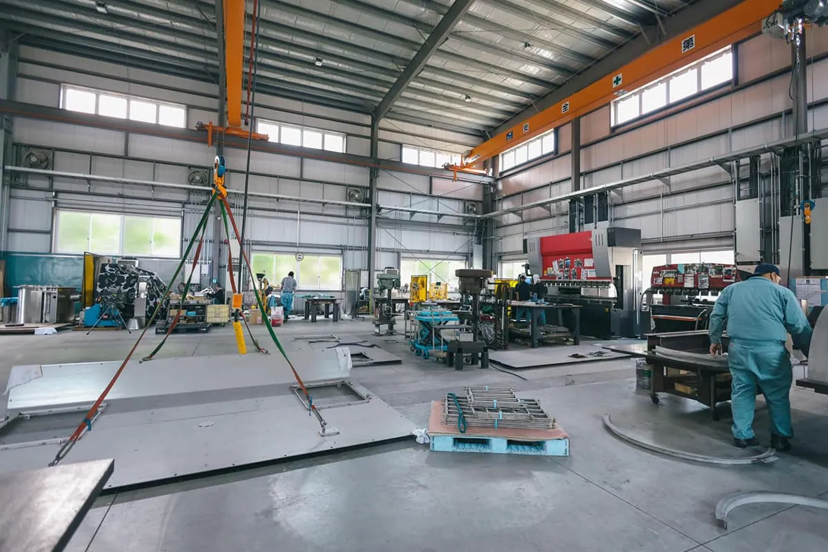
The main equipment for the fabrication of sheet metal components includes shearing machines, presses (punching machines), roll beds, flanging machines, drilling machines, grinding machines, gas welding, and electric welding, among others.
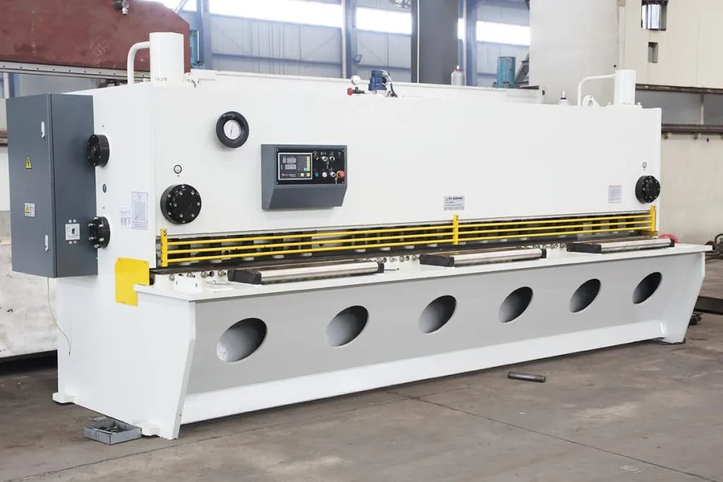
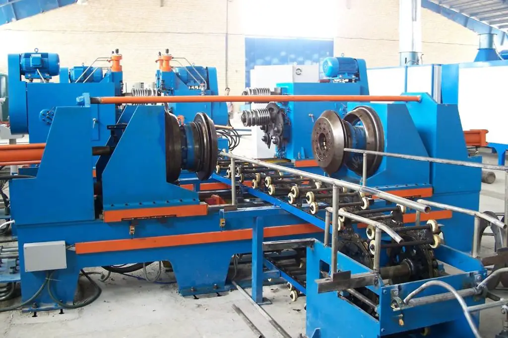
Also known as a plate shearing machine. Commonly used shearing machines include gantry shears, vibrating shears, rolling shears, and hydraulic shears.
Now, let’s take the commonly seen 2.5mm×1600mm gantry shear as an example to introduce.
Namely: Shearing thickness—maximum thickness is 2.5mm, minimum thickness is 0.5mm; shearing width—1600mm; shearing angle—1°30′; stroke frequency—55 times/min; backgauge length—maximum 500mm; motor power—3kW; shearing range—low carbon steel plate, copper, aluminum, and some low hardness thin metal plates.
The gantry shear is mainly composed of a bed, bed surface, upper and lower blades, base, pressure device, and transmission system, and is a special equipment for cutting thin metal plates. The cast iron bed is the main body of the entire machine. The flat bed surface is used to place the cut plate, and the pressure device is set to fix the cut plate to prevent misalignment or flipping during cutting.
The 380V motor provides the power, and through the transmission system (belt, pulley, connecting rod, eccentric shaft, and other parts), the power is transmitted to the upper blade to complete the vertical impact action from top to bottom. The lower blade is fixed on the bed, and with the combined action of the upper and lower blades, the plate is cut.
In addition to completing the main cutting action, the working mechanism also has a pressure device, backgauge, braking device, and safety device. The pressure device functions to press the plate tightly when the upper blade moves down for cutting, through an eccentric mechanism, to prevent misalignment and flipping.
The front and back backgauges and angle backgauges are used to align the sample plate for cutting the plate according to the sample plate specifications.
The braking device is used to control the main spindle camshaft to be at top dead center when stopping, and it helps to balance the stability of the reciprocating motion of the upper blade. The safety device is to set a guard plate in front of the blade to prevent cutting accidents.
The gantry shear can cut parts or blanks with various linear contour shapes such as rectangles, parallelograms, trapezoids, triangles, or polygons. Its advantages include ease of use, simple feeding, fast cutting speed, and high precision.
When cutting large or low-precision sheet metal, it is possible to directly mark lines on the sheet and align with the lower blade before cutting. For mass production, it is also possible to mark reference lines on the worktable instead of using a stopper.
1) The machine must be maintained and operated by designated personnel, and the operators must be familiar with the machine’s performance.
2) The blade edge should be kept sharp, and if any damage is found, it should be replaced promptly.
3) Before starting the machine, check the surface quality of the sheet metal. If there are defects such as hard scars or welding slag, cutting should not be carried out to avoid damaging the blade.
4) Machine operation should strictly follow the operating procedures, and overloading should be avoided.
5) In the event of any abnormal phenomena during use, the machine should be stopped immediately for inspection and repair.
6) After use, the power should be cut off.
7) After machine maintenance, a trial run should be conducted, paying attention to the motor’s direction of rotation and specified speed.
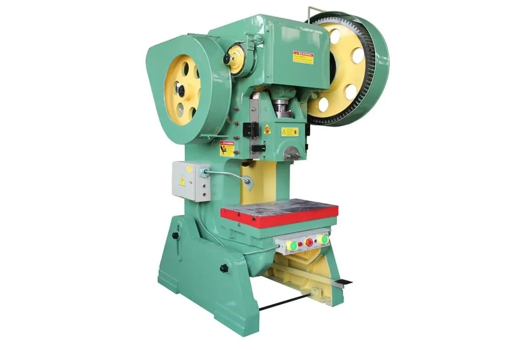
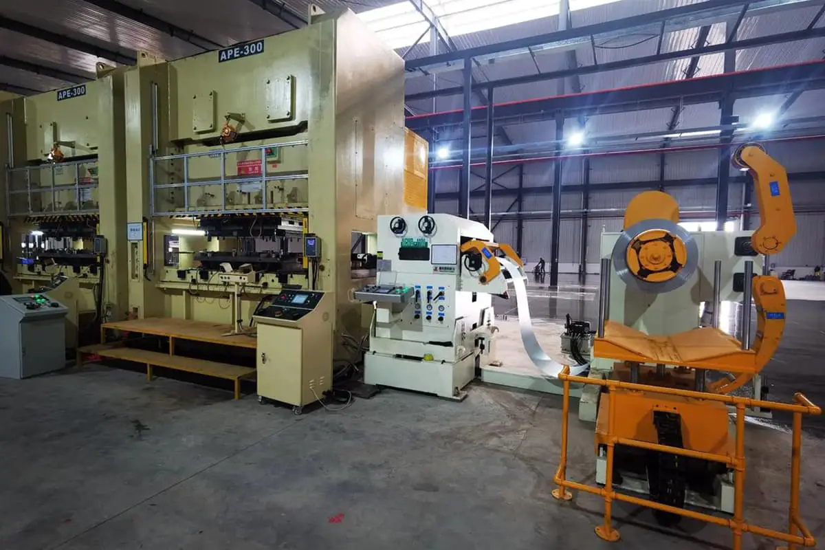
A press machine (also known as a punch press) is a type of equipment that can both cut and form materials. When in use, it only requires a change in the structure and type of the mold: the former uses a cutting die, while the latter uses a forming die.
When processing large parts, a large press machine with a force of 800 kN is used, while for medium and small parts, eccentric presses and crank presses with smaller tonnages are commonly used, with specifications such as 100 kN, 160 kN, and 250 kN. Let’s take the example of a 100 kN open-type double-column inclinable press machine for explanation.
Namely: Nominal force—100 kN, slide stroke—45mm; maximum shut height—180mm; working table area—240mm×370mm; maximum inclining angle—35°; motor power—1.1 kW.
The open-type double-column inclinable press machine is a type of crank press. It is powered by an electric motor, and through belt transmission and reduction, the driven wheel with belt transmission is the flywheel. The mass and size of the flywheel are larger than other components, so it has a large inertia when running, allowing it to store and release a certain amount of energy to reduce the fluctuations caused by the machine’s rotational speed.
The flywheel is connected to the main shaft (the crankshaft) through a clutch, and the crankshaft drives the connecting rod, enabling the slide to move in a straight line along the track.
The upper die is fixed on the slide, and the lower die is fixed on the working table. The working mechanism of the press machine relies on the impact action of the upper die and the lower die to complete the punching, cutting, or bending of thin metal sheets.
The press machine is supported by a frame. The bed is the main body that supports the parts, and blank materials and workpieces can be placed on the working table. The electrical box is installed at the bottom of the bed, and the foot pedal controls the clutch to control the movement and stopping of the upper die.
Equipped with appropriate cutting tools and molds, the press machine can be used for cutting, punching, blanking, bending, and shallow drawing, among other cold forming processes. The press machine body can be tilted to a certain angle to allow the workpiece to slide down from the die on its own. The press machine can perform single or continuous punching and cutting.
1) Precautions before work:
①Tidy up the site, remove any unrelated items, and place the blanks properly;
②Check the lubrication of the press machine’s mating parts and add sufficient lubricating oil;
③Check if the punching die is securely installed and if the cutting edge has any cracks, dents, or damage;
④Always start the electric motor after the clutch is disengaged;
⑤Test the action of the brake, clutch, and controller for flexibility, accuracy, and reliability, and perform several unloaded strokes without a load;
⑥Prepare various tools needed for work.
2) Precautions during work:
①Regularly add lubricating oil;
②Do not cut or trim two pieces of sheet metal at the same time;
③During work, promptly remove the burrs and waste edges cut from the worktable, and use a hook for removal, strictly prohibiting direct use of hands. If the workpiece gets stuck on the die table, the machine should be stopped before clearing it;
④When performing shallow drawing, pay attention to the cleanliness of the blank and apply some lubricating oil on the workpiece;
⑤When using the foot switch, be sure to remove your foot in time to avoid accidental activation and accidents;
⑥Do not reach into the die while the press machine is operating;
⑦If any abnormal operation is noticed (such as the slide freely falling, abnormal knocking or noise, burrs on the finished product, or poor quality), the machine should be stopped immediately, and solutions and countermeasures sought;
⑧Do not dismantle safety protection devices (such as covers, casings, etc.) at will.
3) Precautions after work: ①Disengage the clutch, i.e., disengage the clutch and turn off the power; ②Clean up the waste and work area; ③Organize the tools and the components of the punched products and place them in the appropriate location; ④Wipe the machine body and the die.
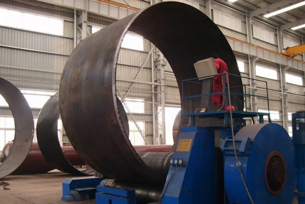
A rolling machine, also known as a plate rolling machine, is a type of equipment that produces bending deformations in flat plates through the rotation of the roller shafts. Let’s take the example of a 2mm×1500mm three-roll rolling machine for explanation.
Namely: Maximum plate thickness—2mm; maximum plate width—1500mm; minimum diameter for making pipes—150mm; working roller shaft speed—35r/min; roller shaft diameter—100mm; motor power—3kW; motor speed—950r/min.
The three-roll rolling machine is composed of three symmetric or asymmetric roller shafts. The primary power comes from a 380V electric motor, which is transmitted to the upper and lower roller shafts and the adjustment shaft through a gear system. The spacing between the three roller shafts can be adjusted at any time according to the size of the bending radius of the plate.
The layout of the three roller shafts is shown in Figure 1-41, with two types: symmetric and asymmetric. Their common feature is that the lowest point of the upper roller shaft is lower than the highest points of the two lower roller shafts.
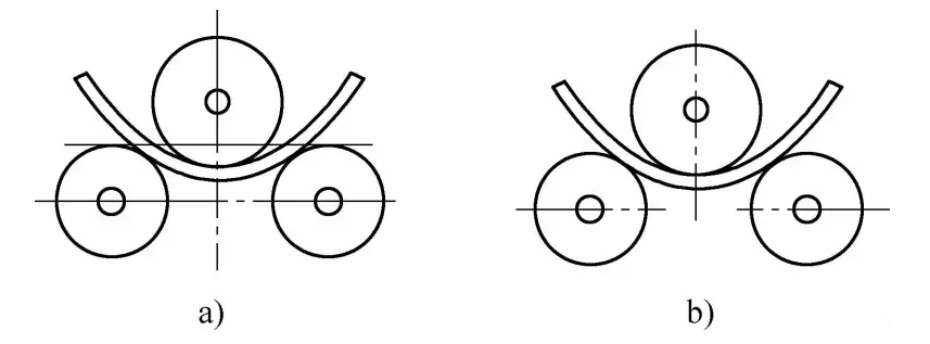
a) Symmetrical Type
b) Asymmetrical Type
Sheet metal is automatically advanced and bent into shape under the combined action of rotating roller pressure and friction. The degree of bending of the sheet metal depends on the relative position of the rollers, the thickness of the material, and its mechanical properties.
This roll lathe can roll metal sheets with a thickness of 2mm and a width below 1500mm into cylindrical parts with constant curvature, parts with variable curvature, as well as conical parts with constant or variable curvature.
1) Before starting the machine, lubricate it first, and check if all parts of the machine are functioning properly. If any issues are found, they should be resolved promptly.
2) Avoid overloading during operation.
3) After operation, cut off the power supply and wipe down the machine.
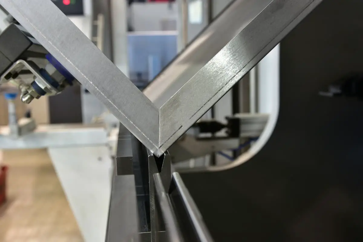
The flanging machine, also known as the folding machine, is primarily used to bend and fold the sheared sheet metal along a straight line to achieve the desired 90° angular corners.
The flanging machine consists of an electric motor, a transmission mechanism, upper beam, lower beam, folding beam, and bed frame. The upper and lower beams are composed of two modules corresponding to a 90° angle, where the upper module protrudes at a 90° angle, and the lower module features a recessed 90° transverse groove.
The recessed 90° transverse groove of the lower module is fixed on the base of the flanging machine. The workpiece can be placed on the lower beam, with the workpiece positioned against a stop block. The electric motor provides the primary power, and through the transmission system, it drives the movement of the upper beam and the folding beam.
The upper beam exerts pressure on the workpiece, while the folding beam rotates to bend the workpiece, thus creating the flange. The process of flanging is as follows: the sheared sheet metal is placed on the lower module’s recessed groove, aligning the straight line drawn on the sheet with the bottom corner line of the lower module’s recessed groove.
Then, the electric motor is started, and through the transmission system, it slowly moves the upper module downward until the upper and lower modules are completely closed, causing the sheet metal to curl up on both sides of the straight line, achieving the desired 90° angular corner.
1) Before work, the work area should be cleaned, the workpieces to be bent should be neatly stacked, and all lubrication orifices of the machine should be filled with lubricating oil.
2) According to the width of the workpiece’s flange and the process requirements, adjust the position of the stop block, the gap between the folding beam and the upper beam, and the rotation angle of the folding beam.
3) After work, the power should be cut off first, and then the machine should be wiped clean.
4) Clean the work site and neatly stack the workpieces.
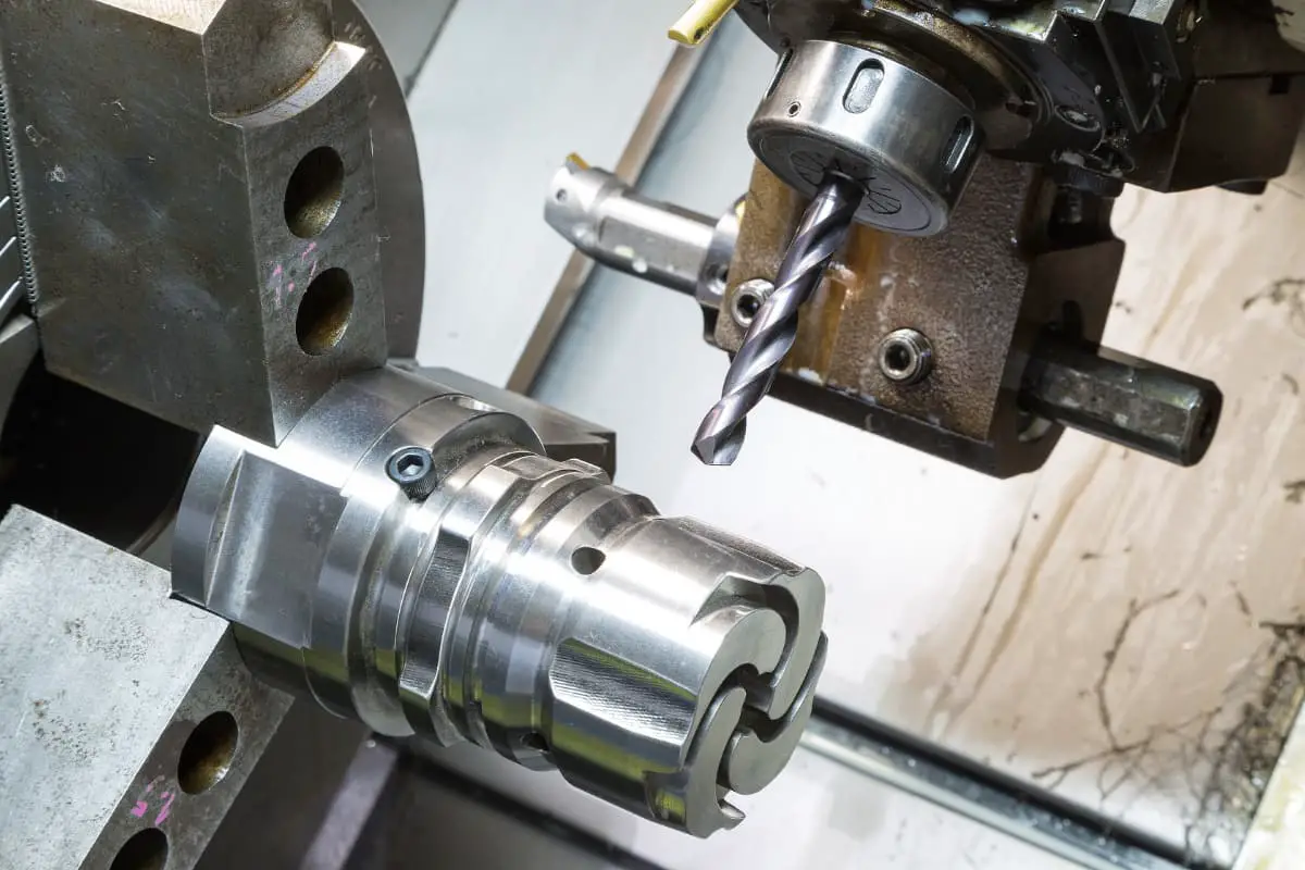
A drilling machine used to drill holes in solid workpieces is called a drilling machine. The main purpose of a drilling machine is to process holes in components, such as rivet, screw, and pin holes for connections, installation holes for transmission parts and bearings, tapping holes, oil holes, and various other process holes.
When drilling or reaming holes, the workpiece should remain fixed. The cutting tool (i.e., the drill bit) can perform two coordinated movements: continuous rotational cutting motion around its own axis and a feed motion downward along the axis. The operator holds the feed handle and gradually applies appropriate force downward.
As the hole is about to penetrate, the force on the feed handle should be gradually reduced to prevent the drill bit from lifting the workpiece and causing injury.Drilling machines can generally be divided into three types: bench drills, radial arm drills, and handheld electric drills.
1) Bench Drill:
Smaller bench drills placed on the bench are referred to as bench drills, which come in two types: tabletop and floor-standing. The tabletop bench drill is usually fixed on the workbench, with a maximum drilling diameter of 13mm and a minimum drilling diameter of 0.1mm. The tabletop bench drill is compact, flexible, and easy to use, serving as the primary equipment for drilling small-diameter holes in small parts.
The larger bench drill is the floor-standing type, which is connected to the ground with base positioning bolts.
The floor-standing bench drill consists of an electric motor, spindle gearbox, column, feed box, spindle worktable, and machine base. The spindle gearbox is equipped with a variable speed device, with higher speeds generally chosen for drilling small holes and lower speeds for drilling larger holes. It comes in several maximum drilling diameters such as 25mm, 35mm, 40mm, and 50mm, with its specifications indicated by the maximum drilling diameter.
There are various styles and sizes of bench drills, but their construction and working principles are fundamentally the same: the electric motor transmits power, driving the drill bit to rotate and complete the cutting action, while the feed handle controls the feed speed.
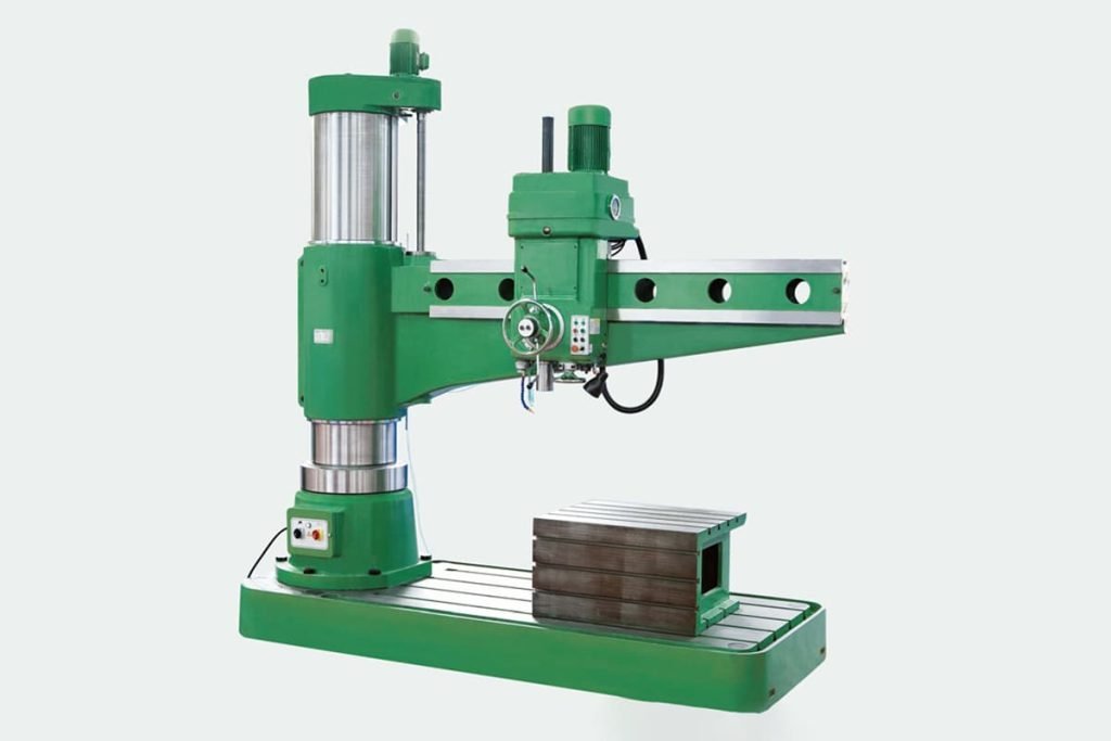
2) Radial Drill:
The radial drill press has a more complex structure, a high degree of automation, and a wide range of applications, making it a high-precision large drill press suitable for hole processing of large workpieces, generally with relatively large drilling diameters.
The radial drill press consists of a column, arm, spindle box, spindle, worktable, and machine base. The spindle box is suspended on the arm and can move left and right on the arm. One end of the arm encloses the column, and the arm can rotate around the axis of the column and move up and down along the column.
The arm position is fixed by a braking device, allowing the spindle box to be aligned with the workpiece at any position within the allowable length of the arm. The spindle is equipped with a drill chuck at the bottom, capable of drilling holes of any position and size on the workpiece.
3) Handheld Electric Drill:
The handheld electric drill is a handheld drilling tool powered by electricity, and the feeding action is completed by the operator’s personal pushing force. Its features include flexibility, portability, and freedom from spatial constraints. For large workpieces or workpieces with relatively small and immovable apertures, using a handheld electric drill is more convenient.
The power supply voltage for the electric drill is 220V or 36V, and the size specifications are divided based on the maximum drilling diameter, such as 6mm, 10mm, 13mm, and so on. There are two types: pistol-grip and handheld.
Precautions for drilling holes
1) When using a handheld electric drill, attention should be paid to electrical safety, such as ensuring a secure power connection, high insulation level to prevent electric leakage, and the installation of residual current circuit breakers during wiring.
2) The drill bit should be securely clamped, and during the drilling process, it should be regularly cooled, for example, by spraying a water solution.
3) When drilling through-holes, reduce the feed rate just before breakthrough. If using automatic feed, switch to manual feed at this point. The downward force applied to the feed handle should be minimized to prevent the drill bit from lifting the workpiece and causing injury.
4) When the hole diameter exceeds 30mm, it should be drilled in two stages. First, drill a small hole with a diameter larger than the width of the cutting edge of the larger drill bit to reduce axial force (generally, a drill bit with a diameter approximately ~ of the hole diameter is used to drill the small hole first).
5) Before drilling through-holes, adjust the stopper on the spindle of the drilling machine to the required depth, or fit a positioning ring on the drill bit.
6) When the material is hard or the drilling depth is significant, the drill bit should be continuously withdrawn from the hole during the drilling process to remove chips and prevent the drill bit from overheating or being jammed and broken by metal shavings.
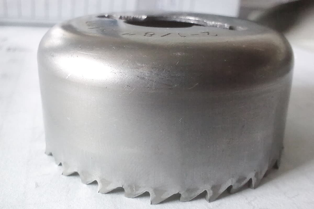
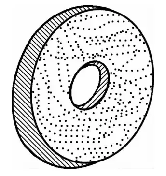
During the manufacturing or repair process, burrs and protrusions produced on the workpiece need to be removed. In this removal process, a flat disc composed of a mixture of adhesive and abrasive particles is used, which is called a grinding wheel (refer to Figure 1-42). The equipment used to frictionally remove the excess waste material from the workpiece is called a grinding machine.
The grinding wheel is mounted on the shaft of the mechanical rotor. The high-speed rotation of the mechanical rotor drives the synchronous rotation of the grinding wheel. By utilizing the high-speed rotating grinding wheel to frictionally remove the excess waste material from the workpiece.
There are two common types of grinding machines in factories: bench grinding machines and handheld grinding machines.
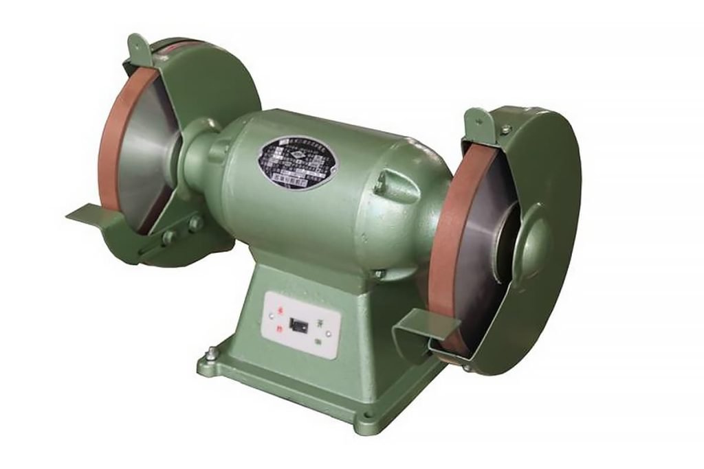
1)Bench Grinding Machine:
There are two types of bench grinding machines. One is small and fixed on the workbench, and the other is a larger floor-standing type with a base fixed to the ground.
A bench grinding machine has an electric motor enclosed and fixed on the motor frame. The rotor of the electric motor is a through shaft, with a grinding wheel attached to each end of the shaft, secured by tightening bolts and a guard plate. The grinding wheel is externally equipped with a protective cover connected to the grinding machine housing.
The large floor-standing grinding machine has a support platform at both ends of the machine body, used to support large or heavy workpieces to reduce the manual force required. The support platform can be adjusted up and down, front and back, to adjust the distance gap. There are four bolts on the support platform to fix it in place. The gap between the support platform and the edge of the grinding wheel is generally between 5-10mm.
As the grinding wheel is consumed and worn, the gap between the support platform and the edge of the grinding wheel should be adjusted in a timely manner. If not adjusted in time, if the gap is too large, the workpiece is prone to getting stuck during the friction process.
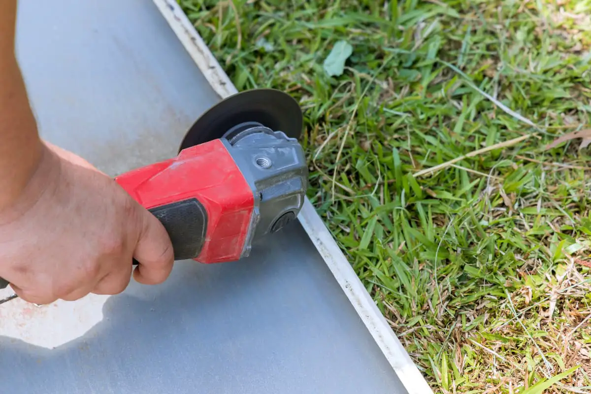
2)Handheld Grinding Machine:
It is a type of grinding machine that is mobile and not restricted by site or orientation conditions. During operation, the workpiece being ground is held in place, and the grinding machine moves around the fixed workpiece for grinding. The handheld grinding machine has only one grinding wheel, which is securely fastened to one end of the through shaft of the electric motor rotor.
The grinding wheel is externally equipped with a protective cover connected to the machine body, serving as a safety protection. The electric motor leads are temporarily connected to the power supply line. One end of the elongated grinding machine housing is a handle, near the grinding wheel, and the other end is a grip handle, with a switch button on the machine body.
During operation, the operator grips the handle and grip handle with both hands, applies even force, and lightly touches the workpiece being ground.
1)Before using the grinding machine, check for any cracks in the grinding wheel and run it empty for 1 minute.
2)Operators using the grinding machine should wear safety glasses.
3)When grinding the workpiece, force should be applied evenly, not excessively. When the workpiece heats up, it should be promptly cooled in water.
4)Regularly check the support platform and adjust it as needed to ensure a gap of 5-10mm.
5)Operators should stand at the side of the grinding machine, not directly in front of the grinding wheel, to avoid being unable to evade accidents.
6)The grinding machine must be equipped with a protective cover to ensure personal safety.
7)When handling the handheld grinding machine, handle it gently, and during operation, stand firmly and hold it securely.
8)The insulation of the leads of the handheld grinding machine must be maintained at a good level, and during operation, it should be equipped with residual current circuit breakers.
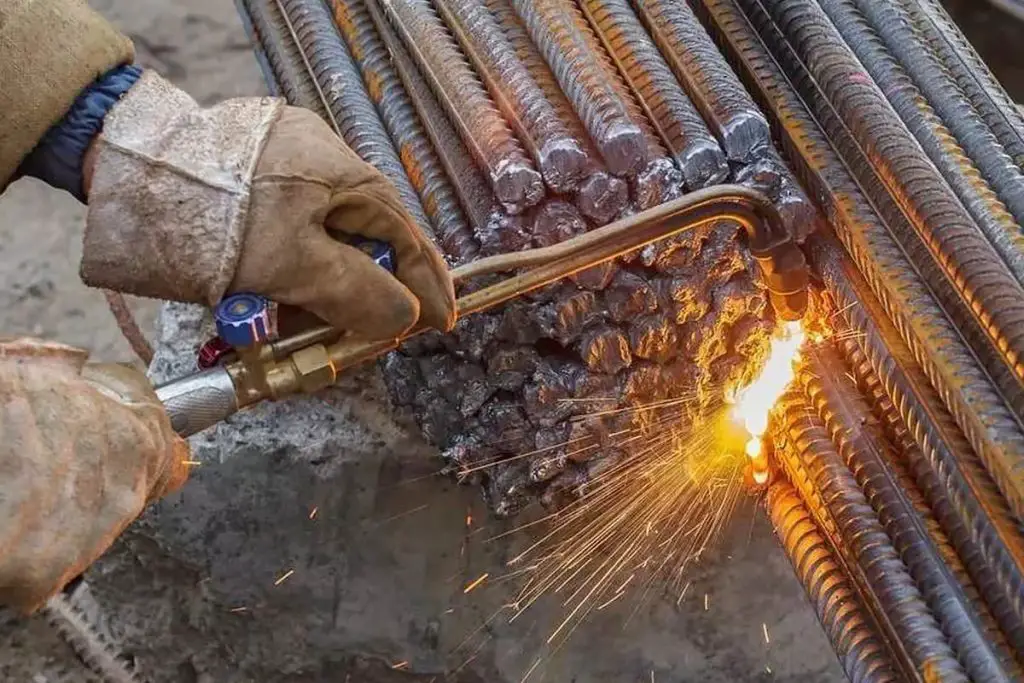
The mixture of combustible gas acetylene and oxidizing gas oxygen can generate temperatures as high as (3-4) × 10^3°C when burned. When directed at low carbon steel plates, the high-temperature flame can directly burn through the steel plate. This equipment, which uses the mixed gas to burn through steel plates, is called gas cutting.
Depending on the different ratios of oxygen and acetylene gas mixtures, three different types of flames can be obtained: neutral flame, carburizing flame, and oxidizing flame.
1) Neutral Flame: When the ratio of oxygen to acetylene is 1 to 1.2, a neutral flame is obtained, in which the resulting gas after combustion contains neither excess oxygen nor excess acetylene. The neutral flame is mainly used for cutting and welding thin sheets of low carbon steel.
2) Carburizing Flame: When the ratio of oxygen to acetylene is less than 1 (generally around 0.85 to 0.95), a carburizing flame is obtained, in which some acetylene remains unburned in the gas after combustion. The carburizing flame is primarily used for welding thin sheets of low carbon steel and for carburizing treatment on the surfaces of some steel plates.
3) Oxidizing Flame: When the ratio of oxygen to acetylene is greater than 1.2 (typically around 1.3 to 1.7), an oxidizing flame is obtained, in which the resulting gas after combustion contains excess oxygen. The oxidizing flame is mainly used for cutting thick plates of low carbon steel, with the oxidizing flame ratio increasing as the steel plate thickness increases.
1) Acetylene and oxygen cylinders should be stored separately with a distance of over 10 meters between them.
2) Acetylene cylinders should be kept in an upright position and not laid horizontally.
3) Handle acetylene and oxygen cylinders with care, avoiding any random collisions.
4) Acetylene and oxygen cylinders should not be exposed to direct sunlight and should be kept away from sources of heat. If necessary, a sunshade should be provided.
5) In the event of a flashback during work, the oxygen valve should be turned off first, followed by the acetylene valve.

Electric welding refers to the metal welding conducted using the high temperature generated by an electric arc.
1) Welding joint forms:
There are generally four types of joint forms: butt joint, lap joint, T-joint, and corner joint (refer to Figure 1-43). Comparison of joint forms: In terms of welding strength, the T-joint is the best, commonly used in welding large parts on ships. The lap joint is better than the butt joint, the butt joint is better than the corner joint, and the corner joint has the lowest strength. Therefore, welding in important areas should avoid corner joints as much as possible.
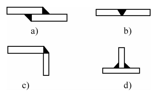
a) Lap Joint b) Butt Joint c) Corner Joint d) T-Joint
2) Weld seam forms:
Weld seams can be divided into flat weld, fillet weld, vertical weld, and overhead weld based on spatial position. Based on structural types, they can be classified as butt weld, corner weld, and plug weld. In terms of continuity, they can be continuous weld or intermittent weld. Based on working mode, they can be working weld or backing weld.
Comparison of weld seams: In terms of quality and work progress, the flat weld is the best, superior to other weld seams. Following that are the fillet weld, vertical weld, and overhead weld, with the overhead weld being the least favorable. Therefore, whenever possible, other types of weld seams should be converted to flat welds (refer to Figure 1-44).
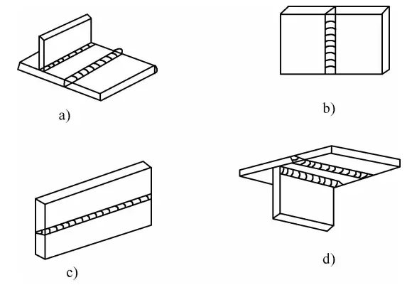
a) Flat Weld Bead b) Vertical Weld Bead c) Horizontal Weld Bead d) Overhead Weld Bead
3) Precautions for electric welding operations:
1.Before starting work, wear various labor protection equipment according to standards and requirements, such as insulated shoes and gloves, and then start the operation.
2.Avoid working outdoors in rainy conditions and in damp or wet areas to prevent electric shock accidents.
3.When working in enclosed containers, ensure ventilation and promptly remove smoke.
4.Do not exceed the welding operation time to avoid damaging the welding machine or cables.
5.After completing the work, promptly turn off the power, tidy up the work area, and arrange the cables.
Hand tools can be roughly divided into four types based on their operating procedures and processes: measuring tools, marking tools, cutting tools, and shaping tools.
Tools used to measure the dimensions, lengths, angles, arc sizes, as well as the inner and outer diameters and thickness of components and materials during cutting processes are collectively referred to as measuring tools.Measuring tools mainly include rulers, protractors, curve rulers, and calipers.
Used to measure straight-line distances, including the following styles and specifications.
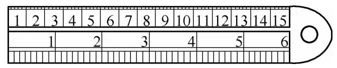
1) Steel ruler:
a commonly used measuring tool available in metric and inch units. Common sizes include 150mm (6in), 200mm (8in), 300mm (12in), 500mm, 600mm, 1000mm, 2000mm, etc. The smallest measurement unit is in millimeters (mm). Figure 1-45 shows a 150mm steel ruler, marked with scales in both inches and millimeters.
2) Tape measure:
Available in steel and cloth varieties. The steel tape measure is made of a long and thin steel strip, which can be fully retracted into its housing when not in use. The steel strip is marked with metric scales.
Common sizes include 1m, 2m, 3m, 5m, etc. The front end of the steel tape has a small hook for measuring distances of small structures and to prevent the entire tape from retracting into the housing. The smallest measurement unit for the steel tape measure is in millimeters (mm).
The cloth tape measure is made of synthetic leather or fabric tape and can be fully retracted into its housing when not in use. It generally comes in two sizes, 20m and 50m. The surface of the cloth tape measure is marked with scales, with the smallest measurement distance in centimeters (cm).
A tool used for measuring and creating angles. Angle measuring tools mainly include the square, the protractor, the universal bevel protractor, and the angle measuring ruler.
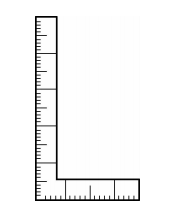
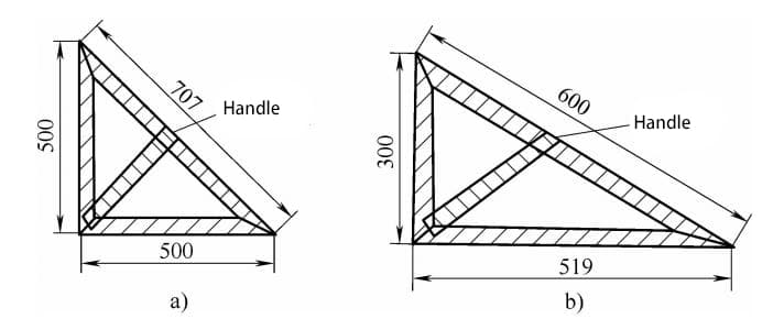
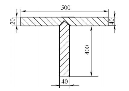
1) Square:
Also known as a 90° angle ruler, it is formed by welding together two straight rulers of different lengths to form a 90° angle. The surface is marked with metric scales and is generally 250mm × 500mm. It is used to measure whether two surfaces of a workpiece are perpendicular or to draw vertical lines on it (see Figure 1-46).
2) Protractor:
The protractor is a tool that can be made by oneself. This tool can measure various internal and external angles on equipment components and can also be used as a template for directly drawing lines on sheet metal (see Figure 1-47).
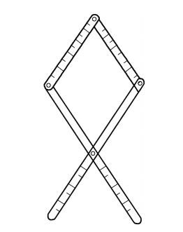
The principle of making a protractor is based on the characteristics of a rhombus, where the four sides are symmetrical and equal, the upper and lower angles are equal, and the opposite angles are equal.
The process of making a protractor:
① Make four strips of equal width, two long and two short, with the long strip being twice the length of the short one.
② Mark each strip at equal distances for measurement.
③ Drill two holes in each strip, with the holes on all four strips equally spaced.
④ The “head” of the protractor consists of two short strips, and the “tail” consists of two long strips. The holes at one end of the two short strips are overlapped and hinged with a shaft. The holes at the other end of the two short strips are overlapped with the holes at the front end of the two long strips and hinged with a shaft. The middle hole of the two long strips is overlapped and hinged with a shaft.
⑤ After the four strips are connected, they form a fish shape, which can be easily adjusted in size. No matter how it is rotated, the angles at the “head” and “tail” are always equal. The “head” is used for measuring internal angles, and the “tail” is used for measuring external angles.
3) Universal Bevel Protractor:
It consists of two rulers, an internal angle ruler, and an external angle ruler, and can measure the relative position and distance between screws and holes on equipment and components. This tool is easy to use, convenient, quick, and highly accurate.
① Construction of the universal bevel protractor (see Figure 1-50):
It consists of a 180° scale disc with a handle and four hinged adjustable strips, two long and two short. The two short strips are used to measure angles on the equipment and components, and the bars of the two long strips are fixed on the upper edge of the scale disc. The other end of one of the long strips matches the scale on the disc and can freely rotate within the 180° scale disc, and the value it points to is the measured angle.
The four strips are hinged together with equally spaced holes using four equal-diameter shafts to form a rhombus, which can be adjusted in size and fixed when measuring angles.
② Working principle:
The universal bevel protractor is composed of four hinged strips forming a rhombus, utilizing the principles of a rhombus where the four sides are equal, the opposite angles are equal, the opposite angles are equal, and the corresponding angles are equal. When measuring internal angles, the two short strips are movable, causing the long strips to move, and the end of the movable long strip rotates on the scale disc. The value it points to on the scale disc is the measured angle because the angle between the two long strips on the scale disc is the angle measured by the two short strips, i.e., the corresponding angles are equal (see Figure 1-48a).
The universal bevel protractor consists of an internal angle ruler and an external angle ruler that work together as a set. The internal angle ruler is used for measuring internal angles, and the external angle ruler is used for measuring external angles. The construction of the external angle ruler is basically the same as that of the internal angle ruler, except that the two short strips are removed, leaving only the two long strips (see Figure 1-48b).
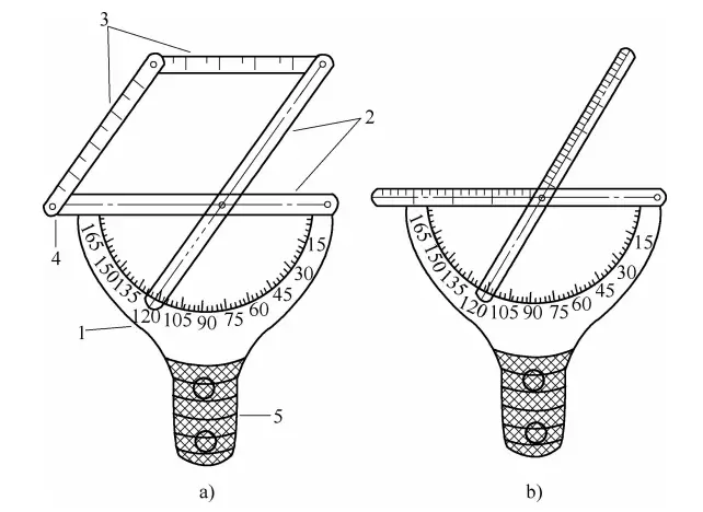
a) Internal Angle Protractor b) External Angle Protractor
1 – Vernier Scale 2 – Long Blade 3 – Short Blade 4 – Pivot Axis 5 – Handle
4) Angle Measuring Ruler:
It is a specialized tool for measuring angles, which can be used to directly draw lines and cut products and materials without using a protractor. It can produce any angle within 180° and can also divide known angles arbitrarily.
Structural features and working principle: The angle measuring ruler consists of two overlaid fan-shaped plates with the middle part removed, forming a hollow half-circle. The arc of the half-circle is marked with a scale of 180°, and a 180mm long scale line is marked in the central lower part of the fan-shaped plate.
Numbers are marked below the scale line, and two bars, one long and one short, are hinged at the upper ends of the two plates. The long and short bars can move freely within the fan-shaped plate, with the long bar matching the 180mm scale line under the fan-shaped plate, and the short bar moving freely along the arc of the half-circle inside the fan-shaped plate.
The long and short bars intersect on the arc of the half-circle, and the point of intersection represents the angle, with the number corresponding to the intersection point on the scale line being the measured angle (see Figure 1-49).
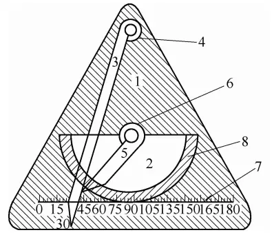
1 – Sector Plate
2 – Sector Plate with Hollowed Center
3 – Movable Long Blade
4 – Long Blade Pivot Axis
5 – Movable Short Blade
6 – Short Blade Pivot Axis
7 – 180mm Graduation Line
8 – Short Blade Rest
The working principle of the angle measuring ruler can be found in the section “Method for Drawing Any Angle in Plane Geometry” in the first section of plane geometry.
The curve ruler is a tool used to measure the arc and curve of product parts during cutting. It can measure both concave and convex curves, that is, internal and external arcs.
1) Main structure of the curve ruler:
The curve ruler consists of a hollow sliding track with a handle, and two long and short adjustable plate bars connected by multiple chain links. The center of the chain is fixed at the top of the hollow sliding track handle. The ends of the chain are connected to one end of the two adjustable plate bars.
The overlapping holes at the other ends of the two bars are fastened inside the hollow sliding track by a concentric axis bolt. The sides of the chain can move up and down, with upward movement used for measuring external arcs and downward movement for measuring internal arcs.
2) Working principle:
When measuring internal arcs, the concentric axis of the plate bars moves downward inside the hollow sliding track of the handle, simultaneously pushing the chain links to tighten against the object being measured. When the object’s arc position matches that of the curve ruler, the concentric axis bolt of the plate bars is fastened to secure the curve ruler (see Figure 1-50b).
When measuring external arcs, the plate bars connected to the concentric axis move upward inside the hollow sliding track of the handle, simultaneously pushing the chain links to tighten against the object being measured. When the object’s arc position matches that of the curve ruler, the concentric axis bolt of the plate bars is fastened to secure the curve ruler (see Figure 1-50c).
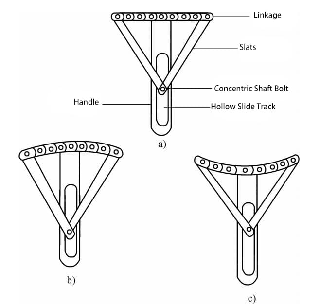
a) Structure of the curve ruler b) Measure internal curves c) Measure external curves
Also known as calipers, it is used to measure the inner and outer diameters of cylindrical or tubular workpieces as well as the thickness of sheet metal. There are two types: internal calipers for measuring the size of apertures or slots, and external calipers for measuring the outer diameter of cylindrical or tubular workpieces as well as the thickness of workpieces and sheet metal.
Both internal and external calipers are indirect measuring tools. After measurement, they need to be checked against a steel ruler to confirm the dimensions.
Scribing is the process of marking out the machining boundaries of a part on the raw material, based on the drawing or the actual part. The tools used for scribing include scribing pins, compasses, long straight edges, steel rulers, protractors, triangular scales, T-squares, flexible curves, die cuts, chalk lines, hammers, and scribers.
Made of carbon tool steel, with a diameter of approximately 3 to 5mm and a length of about 200 to 300mm, the scribing pin has a pointed angle of 15° to 20°, with the pointed end being around 20mm, and it undergoes quenching treatment. When using a scribing pin for marking, it is essential to have guiding tools as assistance, such as a steel ruler, triangular scale, or T-square.
During marking, the pointed end of the scribing pin should be placed closely against the guiding tool, with the upper part inclined outward at 15° to 20° and inclined at around 50° in the direction of movement of the scribing pin. It can be used instead of a scriber and chalk line when laying out material for cutting.
They are used for drawing circles, measuring angles, dividing line segments, and taking measurements. They are typically made of medium carbon steel. Their tips are hardened through quenching treatment. For drawing larger circles, a compass is used, while a straightedge is used to draw large circles on a flat surface.
The triangular scale consists of two right-angled triangles (see Figure 1-51). One triangle has both non-right angles at 45°, while the other has non-right angles of 60° and 30°.
a) 45° angle
b) 60° angle and 30° angle
Triangular scales are typically made from hard, non-deformable wooden strips bonded together. When used together, two triangular scales can create multiple angles in 15° increments, such as 15°, 30°, 45°, 60°, 75°, 90°, and so on.
It is used for drawing vertical lines or for positioning patterns on flat boards. T-squares are typically made by bonding hard, non-splitting, and non-deforming wooden strips together (see Figure 1-52).
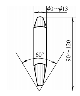
They are generally forged from high carbon steel or made from discarded tool steel. They can be used to mark on steel or to find the center when drilling to avoid eccentricity. When using a sample punch, it should be aligned vertically with the steel plate.
Grip the upper 2/3 of the sample punch with the left hand, exposing the striking part at the top of the sample punch, and strike the top of the sample punch with a hammer using the right hand (see Figure 1-53).
It is often wound with a cotton fine line on a chalk line reel and can be used to draw long lines on large components. When using a chalk line, it requires two people to work together: one holds the chalk line taut, while the other pulls and snaps the taut chalk line, relying on the inertia of the falling chalk line to mark the steel plate.
The hammer used for layout and cutting is generally smaller, typically around 0.4 lb (1 lb = 0.454 kg), and can be used in conjunction with a scribe, prick punch, or small chisel for marking.
A white mineral material, processed into a long, slender shape, primarily used for drawing lines.
The rough material after layout, cutting, and marking is divided according to the template, and the tools used for this process are categorized as cutting tools. Cutting tools include scissors, hand saws, chisels, gas welding, and toothless saws.
This includes tin snips, shears, and fabric scissors.
1) Tin Snips:
There are two styles, straight and curved, made of high carbon steel, with various types and sizes. They are specifically used for cutting thin sheet metal. The straight snips are for cutting straight lines, while the curved snips are for cutting arcs or curves. They generally cut steel plate thicknesses between 0.5 to 1mm, and can cut softer metals such as copper or aluminum below 1.5mm.
When in use, the opening of the scissors should be appropriate, the two edges should be close together, and the cutting edge should be perpendicular to the sheet metal. The angle of the scissor opening should be kept within 15°, as exceeding 15° will cause sliding due to reduced friction between the scissor edge and the sheet metal.
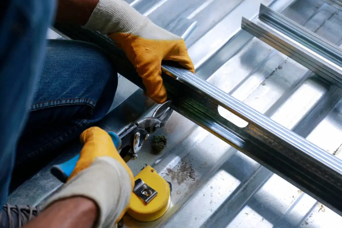
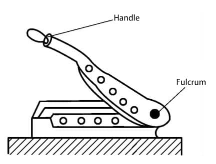
2) Shears:
As shown in Figure 1-54, shears can only perform straight cuts. Because the fulcrum is at the end, they can cut thicker steel plates, typically reaching 1.5 to 2.5mm for low carbon steel plates.
3) Fabric Scissors:
These are used to cut out some templates when laying out materials, such as yellow cardboard, oilcloth, thin iron sheets, and so on.
A handsaw is composed of a saw blade and a saw frame. Common hand saws are divided into fixed and adjustable types based on their length. Adjustable saws can accommodate saw blades of different lengths. Saw blades are generally made of carbon tool steel and can also be made of alloy steel, but they require heat treatment.
The specifications of a saw blade are indicated by the distance between the mounting holes at its two ends. The more teeth within 25mm, the finer the saw teeth; conversely, the fewer teeth within 25mm, the coarser the saw teeth. Coarse-toothed saw blades are suitable for cutting soft metals, while fine-toothed saw blades are suitable for cutting hard metals.
In actual work, sawing involves pushing the saw with force, so when mounting the saw blade onto the saw frame, the saw teeth should face forward.
A chisel is a cutting tool made of forged carbon tool steel and heat-treated, with a wedge-shaped cutting edge that is struck with a hammer.
The chisel consists of three parts: the chisel head, chisel body, and chisel edge (see Figure 1-55). The chisel head has a convex top surface that tapers from fine to coarse towards the chisel body, transitioning into a conical shape. Its characteristic is that the hammer strike point is directly aligned with the center of the chisel edge, making it less likely to deviate during striking and resulting in smooth chiseling without damaging the chisel edge.
The length of the chisel body is determined by the processing requirements and the size of the worker’s hand. The chisel body is often made octagonal to prevent the chisel from rotating during use.
The chisel edge, or cutting edge, consists of two cutting surfaces forming a wedge, and the angle between them is called the wedge angle, denoted as angle “a”.
The size of the wedge angle directly affects the chiseling of the workpiece. A smaller wedge angle requires less effort for chiseling, but if it is too small, the cutting edge becomes weak and prone to damage.
Conversely, if the wedge angle is too large, more effort is required for chiseling, and the cutting surface is not smooth. The size of the wedge angle should be determined based on the material being chiseled; softer materials allow for a smaller wedge angle, while harder materials require a larger one.
During use, the chisel edge may become dull, and the chisel head may develop burrs or rolled edges, requiring attention. In such cases, grinding on a grinding wheel is performed to ensure both the cutting edge and the head meet the usage requirements. Chisels come in various styles based on work requirements, including flat chisels, pointed chisels, and groove chisels.
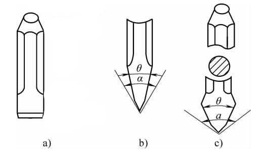
a) Structure of chisels b) Flat chisel c) Point chisel
Mainly used for cutting iron plates above 3mm in thickness, the cutting is done along the cutting line. The cutting speed is dependent on the thickness of the plate; it can be faster for thinner plates and slower for thicker ones.
After marking, cutting, and shearing the blank or the component that needs to be repaired, the next step in the process is shaping and forming, which involves flattening, bending, folding, closing, connecting, positioning, notching, riveting, or welding the workpiece. The tools used in these processes are categorized as sheet metal forming tools.
There are many types of sheet metal forming tools, including pliers, wrenches, hammers, files, screwdrivers, anvils, flat bars, square bars, round bars, scribes, chromium iron, blowtorches, mallets, punches, forked levers, and expanders.
Primarily used for gripping and securing various small workpieces or individual components, pliers come in many types, including wire-cutting pliers, flat-nose pliers, needle-nose pliers, duckbill pliers, hand vise pliers, machine vise pliers, bench vise pliers, and pipe pliers.
1) Wire-cutting pliers, flat-nose pliers, needle-nose pliers, and duckbill pliers are all single-handed grip pliers. Wire-cutting pliers are used for clamping small parts and cutting various metal wires. Needle-nose pliers are suitable for narrow and shallow areas, while flat-nose pliers are used for elongated gaps.
2) Hand vise pliers and machine vise pliers are both small gripping tools. Hand vise pliers, a handheld bench vise, are used for clamping small workpieces and thin sheet metal, primarily for filing, shaping, and drilling. They are convenient to carry and use, not restricted by conditions or location, and their specifications are determined by the width of the jaws, typically around 45mm.
Machine vise pliers are fixed to the workbench and used for clamping medium to small flat workpieces, mainly for filing and shaping. The base of the machine vise pliers has four screws that secure it to the workbench.
3) Bench vise pliers are relatively large gripping tools fixed to the workbench. They consist of a base, plier body, and jaws. The circular base of the bench vise pliers has three bolts connected to the workbench.
The base has a turntable connected to the plier body. The plier body can rotate 360° under the action of the turntable, and it has two bolts to fix the plier body in place. The plier body is composed of two opposing jaws. In the center of the plier body, there is a trapezoidal screw that adjusts the distance between the jaws for positioning.
The specifications of bench vise pliers are determined by the width of the jaws. There are many types of bench vise pliers. The specifications commonly used in sheet metal processing are 6in and 10in, indicating jaw widths of 150mm and 250mm respectively. Bench vise pliers are used to grip workpieces for cutting, filing, repairing, and shaping.
The use and maintenance of bench vise and machine vise:
①When using a bench vise and machine vise fixed to the workbench with bolts, the workpiece should not be clamped too loosely or too tightly. If the workpiece surface is smooth and flat, a pure copper sheet can be used to pad the jaws to prevent damage to the workpiece surface.
②The jaws and the moving parts of the bench vise should not have any oil.
③Do not strike the moving parts with a hammer.
④When clamping heavy workpieces, wooden blocks can be added underneath the workpiece as a support to prevent it from falling and causing injury.
⑤The bench vise should be kept clean regularly and lubricating oil should be applied to the moving parts frequently.
4)The pipe wrench is a clamping tool made of cast steel, consisting of jaws and a handle, mainly used for clamping cylindrical and conical workpieces.
The jaws of the pipe wrench have a row of teeth at the upper and lower ends of the jaw lips, which serve to grip cylindrical workpieces. The upper end of the pipe wrench jaws is connected to the handle, and there is a movable gear on the upper end of the handle, positioned within the gear frame.
The lower end of the jaws is an adjustable jaw, connected to a vertical rack, which meshes with the movable gear inside the gear frame, allowing the jaw lips at the lower end to move up and down.
The handle is used to apply external force, facilitating the clamping or flipping of cylindrical workpieces to secure or disassemble the joints of tubular components.
Wrenches are common tools used to tighten or loosen bolts. Common types include adjustable wrenches, monkey wrenches, socket wrenches, and box-end wrenches.
Adjustable wrenches, monkey wrenches, and box-end wrenches are all available in sets and come in both metric and standard (imperial) units. A typical set of adjustable wrenches consists of eight pieces with sizes ranging from 5.5mm to 27mm. Monkey wrench sets consist of seven pieces with sizes ranging from 5.5mm to 24mm, while socket wrench sets consist of 24 pieces, composed of sockets, handles, and ratchets, with sizes ranging from 8mm to 32mm.
The specifications for adjustable wrenches refer to the overall length of the wrench. Common sizes range from 100mm to 500mm, equivalent to 4 inches to 20 inches, available in 4in, 6in, 8in, 10in, 12in, 14in, 16in, and 20in.
Usage and maintenance of wrenches:
1) The selected wrench must fit the size of the nut and should not have any looseness to prevent slipping and causing injury.
2) When using an adjustable wrench, ensure the jaw is adjusted to fit the size of the nut.
3) When using a wrench, apply force mainly on the body of the wrench, keeping it perpendicular to the centerline of the bolt to ensure safety.
4) Use pulling force rather than pushing force when using a wrench. If pushing force is necessary, apply gradual force with the palm to prevent injury if the bolt suddenly loosens.
5) Do not add a pipe to the wrench for increased leverage, and never apply force with multiple people, as this may damage the wrench (except for wrenches designed for additional force).
6) Do not strike the handle with a hammer or use the wrench as a hammer.
7) A large 20-inch adjustable wrench can also be used as a clamp to straighten and restore bent metal plates.
There are many types and styles of hammers used by sheet metal operators, including sheet metal hammers, flat hammers, throwing hammers, square hammers, iron hammers, wooden hammers, and rubber hammers. Different hammers should be chosen according to the specific workpieces.
Hammers can be divided into two types based on the material properties: soft head hammers and hard head hammers. Soft head hammers are generally made of copper, lead, hardwood, leather, or rubber, and are mostly used for working on soft metal workpieces or various assemblies. Hard head hammers are mostly made of carbon steel.
Both ends of the hammer head have undergone appropriate heat treatment. Hammer heads come in three shapes: round, square, and flat. The hammer handle is made of hard and tough wood, with an elliptical cross-section at the grip to facilitate directing the hammer head and prevent the handle from rotating when swinging the hammer.
Using and maintaining hammers:
1) Hammers weighing over 2kg are considered large, while those weighing under 2kg are considered small. When using a large hammer, the right hand is placed in front and the left hand is placed behind, gripping the handle tightly, with the feet positioned apart in a figure-eight stance, with the left foot stepping forward or half a step forward.
When using a small hammer, the right hand grips the handle, with appropriate grip to ensure there is no excessive force in either direction.
2) Before use, check whether the hammer head is securely attached, and it is best to use a wedge to firmly secure the hammer head to the handle.
3) Do not use the hammer with oily hands to prevent the hammer from slipping out and causing injury.
4) If the hammer head or the top of the hammer is oily or has dents, do not use it to avoid causing damage to the processing surface.
5) After using the hammer, it should be properly stored to prevent the handle from breaking or being damaged.
A file is a type of cutting tool primarily used to remove excess metal from the surface of workpieces, and it is a precision machining operation.
1) Construction of a file: A file consists of a file body and a file handle (see Figure 1-56). The file body is made with file teeth for filing, serving as the working part, while the file handle is for gripping. The handle is typically made of wood. The length of a file refers to the length of the file body, and it comes in various specifications.
2) Types and uses of files:
Based on the size of the file teeth, files can be categorized into coarse, fine, and superfine teeth (known as a smooth file). The size of the file teeth depends on the number of file teeth per 10mm, with a greater number of file teeth resulting in smaller file teeth. File teeth are further divided into single-cut and double-cut.
Single-cut file teeth are straight and form an angle of 70° to 80° with the edge of the file, used for filing soft metals or surfaces requiring a relatively smooth finish. Double-cut file teeth intertwine, with the file teeth that are cut first called the bottom-cut teeth, and those cut later called the surface-cut teeth.
The surface-cut teeth form an angle of 65° or 72° with the file edge, while the bottom-cut teeth form an angle of 45° or 52° with the file edge. The spacing of the bottom-cut teeth is larger than that of the surface-cut teeth.
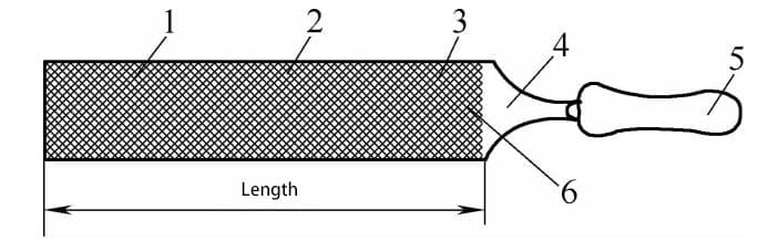
1—File teeth 2—File face 3—Bottom-cut teeth 4—File body 5—File handle 6—Handle
According to the cross-sectional shape, files can be divided into ordinary files (including flat files with parallel edges, tapered flat files, square files, round files, half-round files, triangular files, etc.) and special files (including knife files, rhombic files, flat triangular files, elliptical files, round belly files, etc.).
Finishing files, also known as needle files or Swiss files, are used for precision machining. Each set of files has different shapes, such as five-piece sets, seven-piece sets, ten-piece sets, twelve-piece sets, and so on.
The uses of various files are listed in Table 1-8.
Table 1-8: Uses of Various Files
| File Types | Uses |
| Flat file | File flat surfaces, external cylindrical surfaces, and convex curved surfaces |
| Square file | File square holes, rectangular holes, and narrow flat surfaces |
| Round file | File round holes, small radius concave curved surfaces, and elliptical surfaces |
| Half-round file | File concave curved surfaces and flat surfaces |
| Triangular file | File internal angles, triangular holes, and flat surfaces |
| Knife file | File internal angles, narrow slots, and wedge-shaped slot file square holes, triangular holes, rectangular holes, and internal flat surfaces |
| Elliptical file | File internal and external concave surfaces, round off edges and concave corners of elliptical holes |
| Rhombic file | File teeth of gears, sprockets, and chain wheels |
| Round belly file | File down thick layers of metal (the coarsest file) |
3) Selection and Rules for Using Files: The choice of file depends on the shape of the workpiece, while the selection of the file grade depends on the machining allowance, precision requirements, and material properties of the workpiece. Coarse files can be used for filing soft metals with large machining allowances, low precision requirements, and low surface roughness.
Conversely, fine files are used in the opposite scenarios. New files are sharper and suitable for filing soft metals, while old files are the opposite. Correct usage of files can prolong their lifespan. Therefore, it is essential to avoid using new files for filing hard metals, castings with hard skin or sand particles, and forgings.
These should be ground with a grinding wheel before filing with a semi-sharp or old file. Files should be used on one side, and only when that side becomes dull or when sharp file teeth are necessary should the other side be used. Avoid touching the freshly filed surface by hand to prevent slipping during filing.
A screwdriver, also known as a screwdriver or screwdriver, is a tool used to tighten or loosen screws. There are generally two common types based on their shape and usage characteristics:
1) Flathead screwdrivers typically have a flat blade, and their specifications are indicated by their overall length, with various sizes ranging from 150 to 300mm. The width and thickness of the screwdriver head are proportional to the length of the handle.
2) Phillips head screwdrivers have a cross-shaped head and are suitable for Phillips screws, characterized by being less likely to slip out of the screw slot. They come in four sizes, numbered 1 to 4.
3) Tips for using and maintaining screwdrivers:
When using, ensure the blade is pressed vertically into the screw slot, and avoid applying excessive force.
Hold the handle with the right hand and maintain alignment with the screw using the left hand, keeping it perpendicular to the screw.
It is strictly prohibited to use a screwdriver when the blade does not align with the screw slot.
The handle of the screwdriver and the operator’s hands should be free of oil to prevent slipping during use.
Screwdrivers should not be used as substitutes for pry bars, punches, or chisels.
Its primary function is to flatten workpieces and it is made of medium carbon steel. Depending on the requirements of the workpiece, it can be made in various styles, such as flat plate backing traverse rest and arc-shaped top needle traverse rest. When repairing thin sheets, the traverse rest is placed on the opposite side to resist the hammering force.
Depending on the specific needs during repair, different traverse rests are chosen. For larger areas of protrusions or indentations, a flat plate backing traverse rest is used, while for smaller deformations (such as small protrusions), a top needle traverse rest is employed (refer to Figure 1-57).
a) Flat anvil b) Pointed anvil
1 – Workpiece surface 2 – Handle
The anvils should be kept clean, smooth, free from oil stains, and devoid of any dents or irregularities. After use, they should be stored properly and not thrown or placed haphazardly to prevent damage.
A surface plate, also known as a surface platform, is mostly made of cast iron with reinforcing ribs on the back to increase its strength. The thickness varies; small plates are typically 50-80mm thick, while larger ones range from 200-300mm in thickness. The primary function of the surface plate is to provide a flat and straight surface for sheet metal.
There is no unified specification for the area of the surface plate, but common sizes include 600mm×1000mm, 800mm×1200mm, and 1500mm×3000mm.
Usage and Maintenance of the Surface Plate:
1.The surface plate must be securely fixed on a stand at an appropriate height for ease of operation. The stand is primarily made of wood, serving to dampen vibrations.
2.The surface of the plate must be kept clean and smooth. It should not be subjected to random hammering or used for electrical or gas welding to prevent damage to the surface.
A square bar, commonly known as a “square tube”, is a steel bar about 2 meters long with a cross-section of 20mm × 50mm. It is mainly used for bending, folding, and biting thin sheet metal. One end of the square bar is tapered to facilitate the operation of thin sheet metal. When a square bar is not available, a small iron rail can be used as a substitute.
The four corners of the square bar must be kept intact and not damaged. After use, it should not be thrown around to avoid damaging the four corners of the square bar.
A round bar, made of low-carbon or medium-carbon steel, is a circular steel rod about 1.5 to 2 meters long with a diameter of 30 to 50mm. It is mainly used to manufacture hollow circular components. When a round bar is not available, a round iron tube can be used as a substitute. When using, it should be handled with care.
A line engraving chisel, also known as a line carving tool or stamping tool, is a flat chisel made from a high-manganese carbon steel plate that is about 8~10mm thick and cut to shape. It consists of three parts: the chisel edge, the chisel body, and the chisel top, but it does not have a sharp edge. Its main function is to make the sheet metal bend into a sharp line.
There is no fixed specification, but generally there are two styles: straight line chisels and curved line chisels. Straight line chisels are made with longer chisel edges and shorter chisel tops for ease of use and work.
Curved line chisels are the opposite, with shorter chisel edges and chisel tops that are pointed and slanted. When using a line engraving chisel, it should be aligned vertically with the line on the sheet metal. Hold the chisel handle with one hand and the hammer handle with the other hand, then strike the top of the line engraving chisel with the hammer.
a) Straight chisel b) Curved chisel
1- Chisel head 2- Handle 3- Chisel body 4- Chisel edge
Instructions and precautions for using a line scribing chisel:
1) Before use, check the chisel edge for any defects and ensure that it is straight enough. If necessary, grind it on a grinding wheel and repair it before use.
2) When using, the chisel edge should be perpendicular to the scribed line. The back of the processed sheet should be padded with soft materials such as wood or rubber to prevent the sheet from cracking when hammered.
3) When using a curved chisel, the chisel edge should be perpendicular to the curve drawn on the sheet, and hammered progressively with each strike.
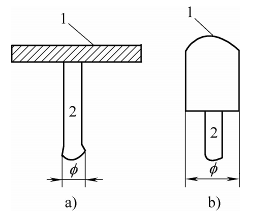
A soldering iron is an indirect heating tool that stores heat after being heated by a heat source, which is used to melt solder and heat solder joints. The material used to make soldering irons is pure copper, which has a slow cooling rate and a long insulation time when heated, and is easy to tin. There are two types of soldering irons: handheld external heating soldering irons and electric soldering irons heated by a power source.
1) Handheld external heating soldering irons are composed of a soldering iron head and a handle. According to the shape of the soldering iron head, it can be divided into hammer-shaped soldering iron, pointed soldering iron, and conical soldering iron.
The hammer-shaped soldering iron head is riveted to the soldering iron handle, and the other end of the handle is equipped with a wooden handle. The lower end of the soldering iron head is a blade-like straight-line chisel, which is the working end. The hammer-shaped soldering iron is suitable for welding long and straight seams.
The pointed soldering iron does not have a handle and is held with pliers when in use, which is suitable for welding recessed parts or narrow places.
The conical soldering iron has a fixed handle and is similar in use to the pointed soldering iron.
All of the above three types of soldering irons are external heating, and the soldering iron heads are generally rectangular blocks. The heating methods are usually oxyacetylene torches, gas welding torches, and stoves.
2) Electric soldering irons belong to the internal heating type, and the soldering iron head is heated by the heat generated by the electric resistance of the power source. The shape and size of electric soldering irons vary, and their electric power also varies in size, generally ranging from 40 to 500W.
They all use a voltage of 220V. When welding electrical components and small parts, a soldering iron with a lower power is used, while a soldering iron with a higher power is selected when welding medium-sized parts or longer seams. The soldering iron head of an electric soldering iron is generally a cylindrical pure copper rod.
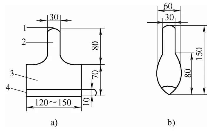
A blowtorch is a closed, pot-shaped metal container filled with gasoline. The pot-shaped shell is equipped with a hand-pressurized cylinder and a nozzle, which are connected to the interior of the container.
By pressing the hand-pressurized cylinder, the gasoline vapor inside the container expands, causing the gasoline to flow through the nozzle pipe towards the nozzle. The gasoline is ignited at the nozzle, and the resulting combustion is used to heat the object. Blowtorches are commonly used in sheet metal fabrication to heat soldered parts and soldering iron tips.
A majority of edge setters are made of hard and resilient wood, while some are made of fiberboard. The standard size is 40mm x 40mm x 400mm, and they are primarily used for rolling and biting thin metal sheets. When in use, avoid using excessive force, and after use, they should be stored in a fixed location to prevent moisture damage and avoid being thrown or placed haphazardly to prevent damage.
A cross wrench is a homemade tool used for repairing sheet metal components. It is mainly made of iron rods or pipes welded into several styles, such as F-shaped, X-shaped, and H-shaped. Its function is to twist and restore the bent edges of sheet metal components to their original position.
The method is to insert the forked head of the cross wrench into the bent edge of the sheet metal component, hold the other end with your hand, and apply force in the opposite direction of the bent edge until it is straightened. Then, use a hammer and a dolly to correct the position of the component.
The expander is a manual tool used to restore collapsed and deformed sheet metal parts. Its main structure includes a base box, a main spindle screw, two nuts, four plate strips, two connecting plates, and a hand crank (see Figure 1-59).
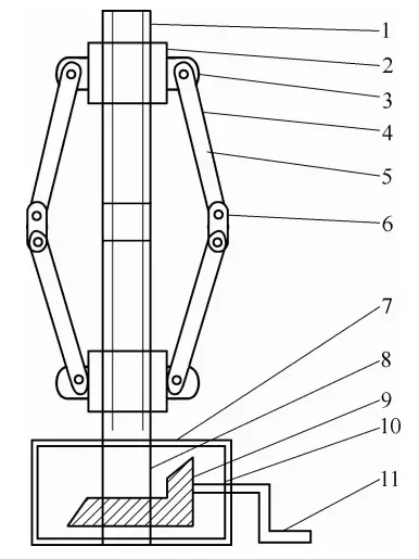
1 – Spindle screw 2 – Nut 3 – Ear 4 – Ear hole 5 – Movable plate strip 6 – Connecting plate 7 – Base box 8 – Large bevel gear 9 – Small bevel gear
10 – Small bevel gear center shaft 11 – Crank
The base box contains large and small bevel gears. The large bevel gear is fixed on the main spindle screw, and the small bevel gear meshes with the large bevel gear. The center shaft of the small bevel gear is connected to a hand crank outside the base box. The meshing of the small and large bevel gears reduces the force required.
The main spindle screw on the outside of the base box has up and down reverse threads, with a small unthreaded section in the middle separating the up and down threads.
There is a nut at each end of the main spindle screw, and each nut has an ear with a shaft hole on either side. The four plate strips with different lengths are connected by the ears with shaft holes, and the two side plate strips are connected to the connecting plates to form a variable diamond shape.
To repair damaged and deformed sheet metal parts, insert the main spindle screw of the expander directly into the collapsed and deformed area, grasp the hand crank, and rotate the small bevel gear to drive the large bevel gear.
This causes the nuts on the main spindle screw to move towards the middle of the screw, and the four diamond-shaped plate strips on the nuts move horizontally, supporting the collapsed area and achieving the desired repair effect.
The above description of the tool’s structure, performance, usage, and precautions is only a brief introduction and not comprehensive enough. Operators need to refer to other materials to complete their understanding. Many tools also need to be manufactured by the operator according to the work environment and on-site needs, as tools are constantly being innovated and improved.