Comprehensive Guide to Bearing Selection Factors
Choosing the right bearing is crucial for the efficiency and longevity of your machinery, but with so many options, where…
The main factors affecting the quality of laser cutting can be roughly divided into two categories: the influence of laser cutting system performance and the influence of laser cutting parameters. The former must be considered when purchasing lasers and establishing a laser cutting system, while the latter relates to how to choose and optimize parameters during the laser cutting process.
The lower the beam mode, the smaller the spot size after focusing, the greater the radiant illumination, the narrower the kerf, and the higher the cutting efficiency and surface quality. Figure 8-8 shows the impact curve of two beam modes on the roughness of the cutting surface. Using a TEM00 mode laser to cut a 2mm thick plate, the cutting surface roughness Rz is only 0.8μm, achieving a very smooth level.
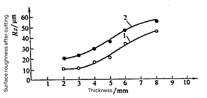
The cutting quality with TEM01 mode is slightly worse, but still maintains a good level. Figure 8-9 shows the impact curve of the two beam modes on cutting speed. As seen in Figure 8-9, when cutting a 2mm thick stainless steel plate with a 500W TEM00 mode laser, the cutting speed can reach 2.0m/min, while with a TEM01 mode laser, the cutting speed is only 1.0m/min.
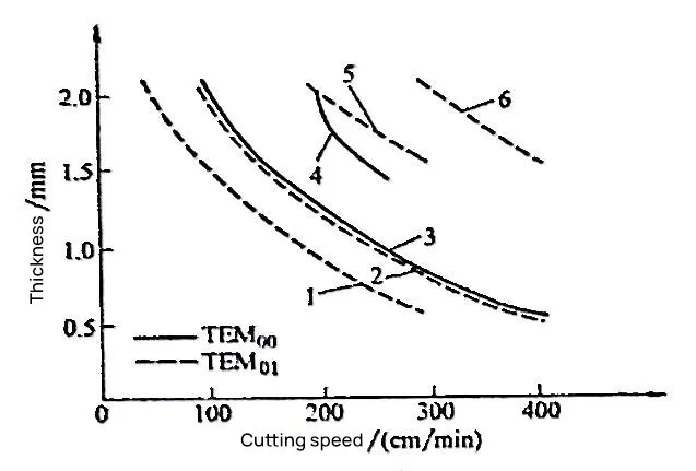
Therefore, to achieve better cutting quality and higher cutting efficiency, it is best to choose a TEM00 mode laser, or at least not higher than TEM01 mode. Lasers with modes higher than TEM01 cannot guarantee cutting quality and should not be used.
The polarization of the laser beam greatly affects the quality and efficiency of laser cutting. If linearly polarized light is used for cutting, the cutting direction changes relative to the polarization direction of the beam, the absorption ratio of the cutting edge to the laser changes, thus affecting the effect of laser cutting.
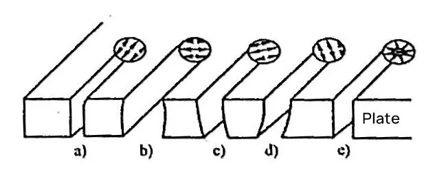
1) When the cutting direction is parallel to the polarization direction, the absorption ratio of the cutting edge to the laser is the highest, so the kerf is narrow, the perpendicularity and roughness of the cut are low, and the cutting speed is fast, as shown in Figure 8-10a.
2) When the cutting direction is perpendicular to the polarization direction, the reflection ratio of the cutting edge to the laser is the highest, the absorption ratio is the smallest, and the lateral absorption ratio increases, so the cutting speed decreases, the cut widens, and the roughness value of the cutting surface also increases, as shown in Figure 8-10b.
3) When the cutting direction is at an angle to the polarization direction, the direction with the highest absorption ratio to the laser is also at an angle to the cutting direction, resulting in a tilt at the bottom of the kerf, as shown in Figures 8-10c and 8-10d.
4) To prevent changes in the shape of the kerf and the quality of the cutting surface due to changes in the cutting direction, circularly polarized light should be used for cutting. The electric vector amplitude of circularly polarized light is equal in all directions, so the absorption ratio of the cutting edge to the laser does not change with the change in cutting direction, and the kerf is uniform and neat, as shown in Figure 8-10e.
In order to convert the linearly polarized light output from the laser into circularly polarized light, a circular polarizer should be added at the exit of the beam.
The pressure and flow of the auxiliary gas are related to the structure and size of the nozzle, both of which greatly influence the quality and speed of laser cutting.
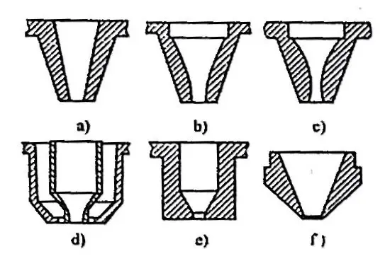
Figure 8-11 lists various structural forms of laser cutting nozzles, among which the conical nozzle shown in Figure 8-11a is the most widely used.
The size of the nozzle aperture must first ensure that the beam can pass smoothly, avoiding the beam inside the hole touching the inner wall of the nozzle. The smaller the aperture, the more difficult it is to collimate the beam, so the aperture cannot be too small.
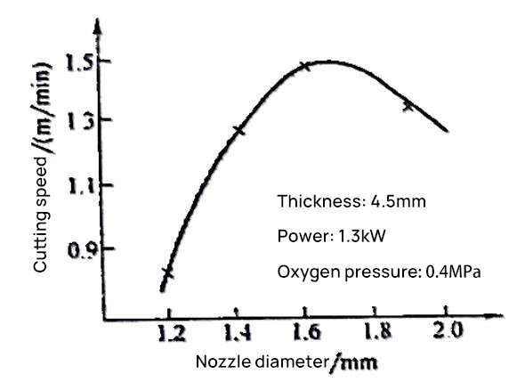
In addition, under a certain auxiliary gas pressure, there is an optimal range for the nozzle aperture. Either too small or too large an aperture will affect the clearance of the molten product in the kerf by the auxiliary gas, thus affecting the cutting speed. Figures 8-12 and 8-13 show the impact of the nozzle aperture on the cutting speed of a 2mm thick low carbon steel plate under certain laser power and auxiliary gas pressure.
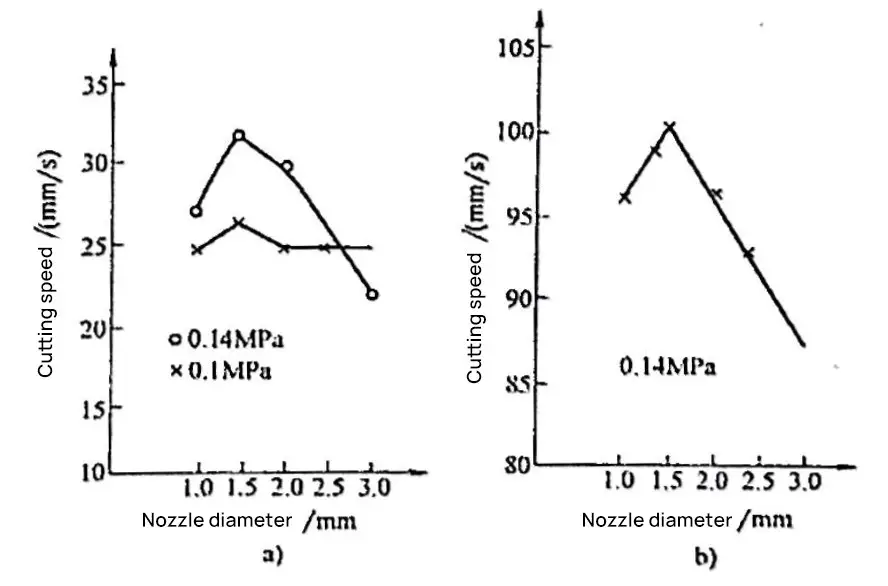
a) Argon
b) Oxygen
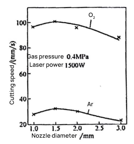
As can be seen from Figures 8-12 and 8-13, there is an optimal nozzle aperture value for achieving the maximum cutting speed. Whether oxygen or argon is used as the auxiliary gas, this optimal value is about 1.5mm. Laser cutting tests on hard alloys, which are difficult to cut, show that their optimal nozzle aperture value is also very close to the above results, as shown in Figure 8-14.
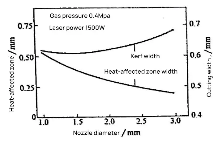
The nozzle aperture also affects the width of the kerf and the size of the heat-affected zone, as shown in Figure 8-15. As can be seen from Figure 8-15, as the aperture increases, the kerf widens and the heat-affected zone narrows. The main reason for the narrowing of the heat-affected zone is that the cooling effect of the auxiliary gas flow on the parent material in the cutting area is enhanced.
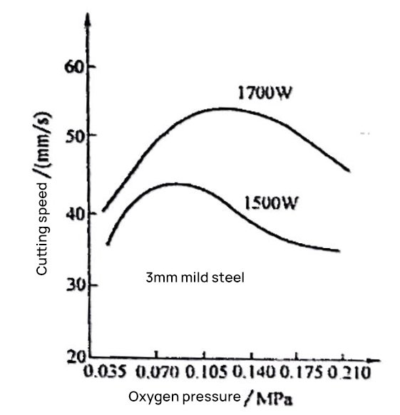
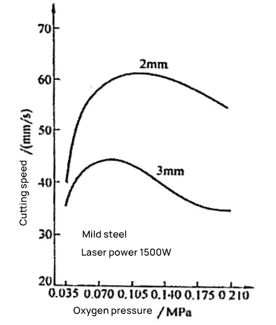
Increasing the gas pressure can improve the cutting speed, but after reaching a maximum value, further increases in pressure will cause a decrease in cutting speed.
As can be seen from Figures 8-16 and 8-17, the maximum cutting speed is a function of the laser power and the thickness of the workpiece plate. At high auxiliary gas pressures, the cutting speed decreases. The reasons for this decrease can be attributed not only to the enhanced cooling effect of high airflow speeds on the laser action area, but also to the interference of intermittent shock waves in the airflow with the laser action area.
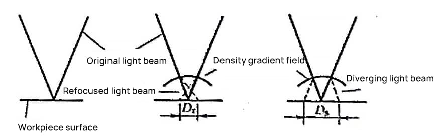
The presence of uneven pressure and temperature in the airflow will cause changes in the density of the airflow field. SteenWM and others have measured that under high gas pressures, there is a density gradient field on the surface of the workpiece directly in front of the nozzle, the shape and size of which depend on the gas pressure, the distance between the nozzle end and the workpiece, and the nozzle aperture.
This density gradient field causes changes in the refractive index within the field, thereby interfering with the focusing of the laser beam, causing refocusing or beam divergence, as shown in Figure 8-18. This interference can affect melting efficiency, and sometimes may change the mode structure, causing a decline in cutting quality. If the beam diverges too much, making the spot too large, normal cutting may even become impossible.
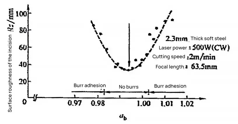
The impact of the focus position on the surface roughness of the kerf is shown in Figure 8-19, where the horizontal coordinate in Figure 8-19 is the ratio ab of the distance from the workpiece to the focusing lens to the focal length.
From Figure 8-19, it can be seen that the smoothest range of the kerf surface is: 0.988 <ab< 1.003, so for general cutting, the focus is usually placed within 1mm below the surface of the workpiece.
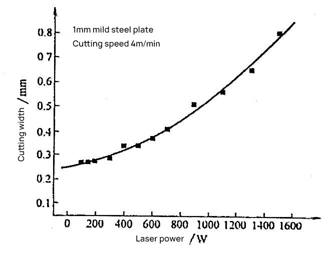
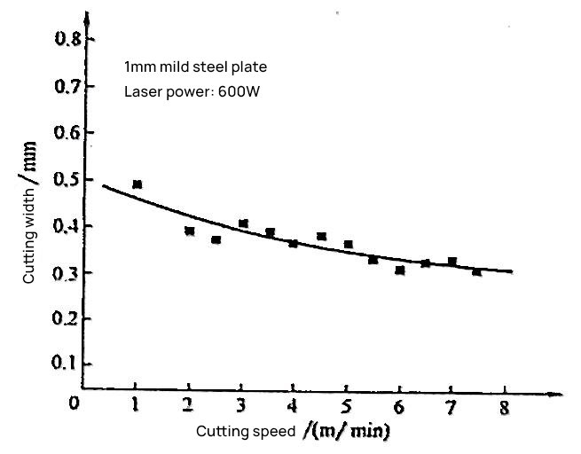
The width of the kerf increases with the increase of laser power and decreases with the increase of cutting speed, as shown in Figures 8-20 and 8-21.
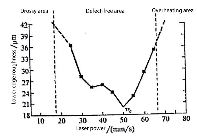
At a certain plate thickness and cutting speed, there is an optimal range of laser power, within which the roughness of the cut surface is the smallest. Deviating from the optimal power range will increase roughness; further increasing or decreasing power will result in overburn or slag defect.
Figure 8-22 shows the relationship between laser power and cutting surface quality when cutting a 2mm thick low carbon steel plate at a cutting speed of 50mm/s (i.e., 3m/min), using the method of measuring roughness near the lower edge. From Figure 8-22, it can be seen that the laser power can be divided into three areas: slag area, defect-free area, and overburn area.
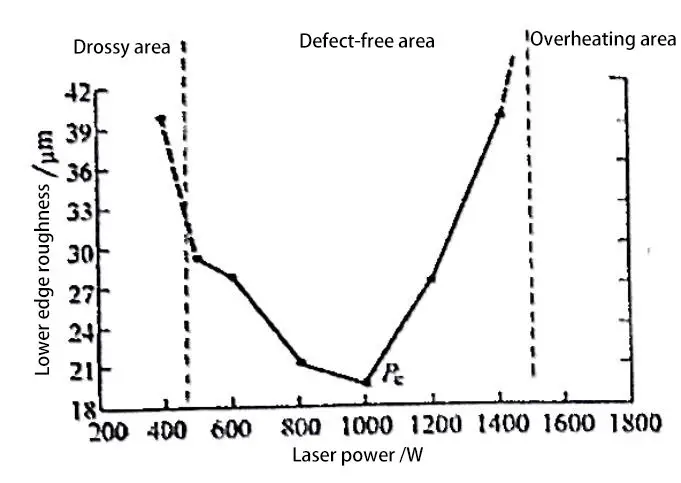
1) If the laser power is too high, causing too much heat input, the melting range of the workpiece is larger than the range that the high-pressure gas stream can drive away, and the molten metal cannot be completely blown away by the gas stream, resulting in overburn.
2) If the laser power is too low, the heat is not enough. The closer to the lower edge, the lower the temperature of the molten product, and the higher the viscosity [11], thus it cannot be completely blown away by the high-pressure gas stream and remains on the lower edge of the cutting surface, resulting in slag. In severe cases, a cut cannot even be formed.
3) Within the defect-free area, there is an optimal range of laser power (about 800~1000W in Figure 8-22), where the roughness of the cutting surface is the smallest.
At a certain plate thickness and laser power, there is an optimal cutting speed, at which the roughness of the cutting surface is the smallest.
Deviation from the optimal cutting speed will increase roughness; further increasing or decreasing the cutting speed will result in overburn or slag defect [5].
Figure 8-23 shows the relationship between cutting speed and cutting surface quality for a 2mm thick low carbon steel plate at a laser power of 1000W, with the vertical coordinate being the roughness near the lower edge. From Figure 8-23, it can be seen that the cutting speed can also be divided into overburn area, defect-free area, and slag area.
If the cutting speed is too low, overburn is caused by excessive heat input; if the cutting speed is too high, slag is produced, or even the cut is not complete.
The reason for the occurrence of slag due to high cutting speed, in addition to insufficient heat input and low temperature causing high viscosity of the molten product, is that the high cutting speed causes the cutting front to tilt significantly backward (increasing trailing amount), which is even more unfavorable for gas flow to blow away the molten product.
Within the defect-free area, there is an optimal cutting speed v (50mm/s in Figure 8-23), where the roughness of the cutting surface is the smallest.