Comparing 303 Stainless Steel and GSS: Key Differences and Applications
When it comes to selecting the ideal material for your next project, the choice between 303 stainless steel and GSS…
To ensure quality, metal forgings must undergo quality inspection. Forgings with defects identified during inspection are determined to be qualified, scrapped, or used after repair based on the usage requirements (inspection standards) and the extent of the defects.
The classification of forging defects is shown in Table 1.
Table 1 Classification of forging defects
| Classification method | Content |
| Production process | 1) Defects generated in the raw material production process 2) Defects generated in the forging process 3) Defects generated in the heat treatment process |
| Process sequence | 1) Metallurgical process defects in raw materials 2) Blanking process defects 3) Heating process defects 4) Forging process defects 5) Cooling process defects 6) Cleaning process defects 7) Heat treatment process defects |
Different processes can produce different forms of defects, but the same form of defect can also come from different processes. Since the causes of forging defects are often related to various factors such as the raw material production process and the post-forging heat treatment process, do not analyze the causes of forging defects in isolation.
The main characteristics and causes of forging defects are shown in Table 2.
Table 2 Main characteristics and causes of forging defects
| Defect name | Main characteristics | Causes and consequences |
| 1. Defects arising from raw materials | ||
| Hairline cracks (splitting) | Hairline cracks located on the surface of the steel, with a depth of 0.5 to 1.5mm | During the rolling of steel, subcutaneous bubbles in the steel ingot are elongated and burst. If not removed before forging, it may cause cracks in the forged parts |
| Scab | A layer of easily peelable thin film that exists in local areas on the surface of the steel, with a thickness of about 1.5mm. It cannot be welded during forging and appears on the surface of the forged part in the form of scabs | During casting, the steel liquid splashes and solidifies on the surface of the steel ingot, and is pressed into a thin film during rolling, which adheres to the surface of the rolled material as scabs. After forging and pickling, the scabs peel off, leaving pits on the surface of the forged part |
| Fold (folding) | Folds appear at both ends of the diameter on the end face of the rolled material, with the fold forming an angle with the tangent of the arc. The inside of the fold contains oxidized inclusions, and decarburization occurs around it | Incorrect sizing of the roll groove on the rolling mill, or burrs produced on the worn surface of the groove, are rolled into folds during rolling. If not removed before forging, they will remain on the surface of the forged part |
| Non-metallic inclusions | Elongated or broken but longitudinally discontinuous non-metallic inclusions appear on the longitudinal section of the rolled material. The former, such as sulfides, and the latter, such as oxides, brittle silicates. | Mainly due to chemical reactions between the metal and furnace gas, container during melting; additionally, caused by refractory materials, sand, etc., falling into the molten steel during melting and casting. |
| Laminated fracture | Often occurs in the central part of the steel material. On the fracture or cross-section of the steel, there appear some morphologies similar to broken slates or bark. This defect is more common in alloy steels, especially in chromium-nickel steel, molybdenum-nickel-tungsten steel, and is also found in carbon steels. | Non-metallic inclusions, dendritic segregation, porosity, looseness, and other defects exist in steel, which are elongated longitudinally during forging and rolling, making the steel fracture appear in layers. Laminated fracture significantly reduces the transverse mechanical properties of steel materials, and forging is very prone to delamination and rupture. |
| Segregation zone | Under a low-power microscope, on the longitudinal direction of some alloy structural steel forgings (such as 40CrNiMoA, 38CrMoAIA, etc.), defects in the form of stripes or bands different from flow lines appear along the flow line direction. The microhardness of the defect area is significantly different from that of the normal area. | The segregation zone is mainly due to the segregation of alloy elements during the production process of raw materials. Slight segregation zones have little impact on mechanical properties, while severe segregation will significantly reduce the plasticity and toughness of the forging. |
| Bright lines or bands | On the surface of the forging or the processed surface of the forging, bright lines of varying lengths appear. Most of the bright lines are distributed along the longitudinal direction of the forging. This defect mainly occurs in titanium alloys and superalloy forgings | Caused by segregation of alloying elements. In titanium alloy forgings, the bright lines mostly belong to areas of low aluminum and low vanadium segregation; on superalloy forgings, the bright line areas often have higher levels of elements such as nickel, chromium, and cobalt The presence of bright lines reduces the plasticity and toughness of the material |
| Carbide segregation level is not up to standard | Often occurs in high carbon alloy steels such as high-speed steel and high chromium cold work die steel, characterized by a local area with a higher concentration of carbides, causing carbide segregation to exceed the permitted standard | Caused by the insufficient breaking and even distribution of ledeburite eutectic carbides in steel during billet opening and rolling Severe carbide segregation can easily cause forgings to overheat, burn, or crack |
| White spots | Circular or oval silver-white spots on the longitudinal section of the steel billet, and fine cracks on the transverse section. The size of white spots varies, with lengths of 1~20mm or longer White spots are common in alloy structural steel and are also found in ordinary carbon steel. | Caused by the high hydrogen content in the steel and the large organizational stress during phase transformation. Large steel billets are prone to white spots when cooled quickly after forging and rolling. White spots are hidden internal cracks that reduce the plasticity and strength of steel. White spots are stress concentration points, which under alternating loads, are prone to cause fatigue cracks. |
| Shrinkage porosity residue | During low magnification inspection of forgings, irregular wrinkle-like gaps appear, resembling cracks, in dark brown or gray-white; under high magnification, a large amount of non-metallic inclusions are found near the shrinkage porosity residue, which are brittle and easy to peel off. | Due to the concentrated shrinkage pores produced at the riser part of the steel chain not being cleanly removed, they remain inside the steel billet during slabbing and rolling. |
| Coarse grain rings on aluminum alloy extruded rods | Aluminum alloy extruded rods supplied after heat treatment show coarse grains in a ring shape on the cross-sectional outer layer, known as coarse grain rings. The thickness of the coarse grain rings gradually increases from the start to the end of the rod. | Mainly due to the presence of elements such as Mn, Cr in the aluminum alloy, and the severe deformation of the rod surface layer caused by friction between the metal and the extrusion cylinder wall during extrusion. Billets with coarse grain rings are prone to cracking during forging, and if left on the forged parts, it will reduce the performance of the parts. |
| Aluminum alloy oxide film | In the low magnification structure of the forging, the oxide film is distributed along the metal flow lines, appearing as black short lines. On the fracture surface perpendicular to the longitudinal direction of the oxide film, the oxide film appears as torn and layered; on the fracture surface parallel to the longitudinal direction of the oxide film, the oxide film appears as flaky or densely dotted. The oxide film inside the die forging is easily seen on the belly plate or near the parting surface. | Oxides not removed from the aluminum liquid during melting are rolled into the metal liquid during the casting process, and are elongated and thinned during the extrusion, forging, and other deformation processes to become oxide films. The oxide film has a small impact on the longitudinal mechanical properties of the forging, but has a greater impact on the transverse, especially the short transverse mechanical properties. Compare according to the category of forgings and the standard of oxide film, only those that are unqualified are scrapped. |
| 2. Defects generated by cutting. | ||
| Skew cutting | The end face of the billet is inclined to the billet axis, exceeding the permitted value. | Caused by the bar material not being clamped tightly during cutting Blanks cut at an angle are prone to bending during upsetting and difficult to position during die forging, easily forming folds |
| The end of the blank is bent and has burrs | During cutting, part of the metal is carried into the gap between the scissors, forming sharp burrs, and the end of the blank is bent and deformed | Due to the gap between the shear blades being too large, or the blade edge not being sharp, resulting in a blank with burrs, forging is prone to folding |
| The end of the blank is dented or protruding | The metal in the center part of the blank end is torn, thus there are protrusions or dents on the end surface | The gap between the blades is too small, the metal in the center part of the blank is not cut but torn, causing part of the metal to be pulled off Such blanks are prone to folding and cracking during forging |
| End cracks | Mainly occurs when cutting large section billets, and such cracks also occur when shearing alloy steel or high carbon steel in a cold state. | Caused by the material’s hardness being too high and the unit pressure on the blade during shearing being too great. Forging will cause the cracks at the ends to further expand. |
| Punch core cracking. | When cutting material on a lathe, a punch core is often left on the end face of the billet. If not removed, it may lead to cracking around the punch core during forging. | Due to the small cross-section of the punch core, it cools quickly; the large end face area cools slowly, thus leading to cracks forming around the punch core. |
| Gas cutting cracks. | Generally located at the end face or end of the billet, the crack mouth is rough. | Insufficient preheating before gas cutting, leading to the formation of large thermal stress and causing it. |
| Grinding wheel cutting cracks | When cutting superalloys with a grinding wheel in a cold state, it often leads to cracks on the end face. These cracks sometimes can only be seen with the naked eye after heating. | Superalloys have poor thermal conductivity, and the large amount of heat generated by grinding wheel cutting cannot be quickly conducted away, forming large thermal stress on the cutting surface, and even producing micro-cracks. Heating again generates larger thermal stress, causing micro-cracks to expand into visible cracks. |
| 3. Defects caused by heating | ||
| Overheating | The phenomenon of coarse grains caused by excessively high heating temperatures. The characteristic of overheated carbon steel is the appearance of Widmanstätten structure; for tool and die steels, it is characterized by primary carbides, and for some alloy structural steels like 18Cr2Ni4WA, 20Cr2Ni4A, besides coarse grains, there is also MnS precipitation along the boundaries, which is not easy to eliminate with usual heat treatment methods. | Caused by excessively high heating temperatures or too long heating times, or due to not considering the effect of deformation heat. Overheating will reduce the mechanical properties of steel forgings, especially plasticity and impact toughness. In general, overheating of steel forgings can be eliminated by annealing or normalizing. |
| “Toad skin” surface | The billets of aluminum and copper alloys form a “toad skin” or a rough surface similar to orange peel during upsetting, and in severe cases, may also crack. | Due to the overheating of the billet, it is caused by coarse grains Aluminum alloy blanks with coarse grain rings will also exhibit this phenomenon during upsetting |
| Widmanstätten α phase or β brittleness | After overheating of the (α+β) titanium alloy billet, the characteristic of its microstructure is that the α phase precipitates along the coarse original β grain boundaries and within the grains in a coarse strip form. The coarse strip-shaped α phase precipitated within the grains is arranged in a certain direction, forming what is called Widmanstätten α phase | The titanium alloy forging with Widmanstätten α phase caused by heating temperature exceeding the β transformation temperature of the (α+β) titanium alloy has significantly reduced tensile plasticity index, which is the so-called β brittleness Heat treatment cannot eliminate β brittleness |
| Overburning of steel forgings | The grains in the overburned area are particularly coarse, oxidation is particularly severe, and the surface between cracks appears light gray-blue After carbon steel and alloy structural steel are overburned, oxidation and melting occur at the grain boundaries. After tool and die steel is overburned, fishbone-like ledeburite appears at the grain boundaries due to melting | Caused by excessive furnace temperature or the billet staying in the high temperature zone for too long. Oxygen in the furnace penetrates along the grain boundaries into the grains, causing oxidation or forming fusible oxide eutectics, which destroys the connection between grains |
| Overburning of aluminum forgings | The surface appears black or dark black, sometimes there are chicken skin-like bubbles on the surface. After the aluminum alloy billet is overburned, its microstructure will show grain boundary melting, triangular grain boundaries, or remelted spheres. The presence of any one of these phenomena indicates overburning | When the heating temperature of the aluminum alloy billet is too high, the strengthening phase melts. After cooling down, coarse grain boundaries, triangular grain boundaries, or special shapes like remelted spheres can be seen in the microstructure |
| Heating cracks | Generally, it cracks along the cross-section of the billet, and the crack expands from the center to the surroundings This type of crack often occurs in the heating of high-temperature alloys and high-alloy steel ingots and billets | Due to the large size of the billet, poor thermal conductivity, and too fast heating speed, there is a large temperature difference between the center and the surface of the billet, resulting in thermal stress that exceeds the strength of the billet |
| Copper brittleness | Cracks appear on the surface of steel forgings. Upon high magnification inspection, copper is distributed along the grain boundaries This defect is likely to occur when steel materials are heated in a furnace that has been used to heat copper materials | The copper oxide scraps remaining in the furnace are reduced to free copper by iron when heated The molten copper atoms diffuse along the austenite grain boundaries at high temperatures, weakening the intergranular cohesion |
| Naphthalene-like fracture | Some shiny small planes like naphthalene crystals appear on the fracture of steel forgings. This defect is easily seen in alloy structural steels and high-speed tool steels | Caused by too high heating temperature or high final forging temperature, and the deformation is not large enough. The essence of the naphthalene-like fracture is overheating, which will reduce the plasticity and toughness of the steel forgings |
| Rock-like fracture | Rock-like fracture is a defect that appears after severe overheating of alloy structural steel. It is observed in the tempered state, characterized by some non-metallic luster, cement-like gray-white small planes appearing on the fibrous fracture matrix. It cannot be eliminated by heat treatment methods, thus it is an unacceptable defect | The heating temperature is too high, causing a large amount of MnS to dissolve, and the MnS dissolved in the steel precipitates on the coarse austenite grain boundaries in extremely fine particles during cooling, weakening the binding force of the grain boundaries. Tempering treatment strengthens the toughness of the steel matrix, and the steel fractures along the austenite grain boundaries during breaking, thus forming some lusterless gray-white overheated small planes on the fracture Forgings with rock-like fractures should be scrapped |
| Low magnification coarse grain | Low magnification coarse grains are another reflection of overheating in alloy structural steel forgings, characterized by the presence of visible polygonal grains on the acid-etched low magnification specimen, which in severe cases appear snowflake-like. | The grain boundaries of overheated austenite grains are relatively stable, and usual heat treatments are unable to eliminate them. Recrystallization only occurs within the coarse austenite grains, generating several new small grains within a single austenite grain. Since the grain boundaries of the small grains are thin or have little orientation difference, the original coarse austenite grains are still seen at low magnification as coarse grains. |
| Decarburization | The carbon content in the surface layer of the steel part is significantly lower than in the interior, and the hardness value is lower than required. The number of cementite phases on the surface decreases under high magnification. Decarburization occurs most easily in high carbon steel heated in an oxidizing atmosphere, especially in steel with a high silicon content. | The carbon in the surface layer of the steel is oxidized at high temperatures. The depth of the decarburization layer ranges from 0.01 to 0.6mm, depending on the composition of the steel, the composition of the furnace gas, temperature, and heating duration. Decarburization reduces the strength and fatigue performance of parts and weakens wear resistance. |
| Carburization | Forgings heated in an oil furnace have a significantly increased carbon content on the surface or part of the surface, increasing hardness. The carbon mass fraction of the carburized layer can reach about 1%, and in some local spots, it can even exceed 2%, showing ledeburite structure, with some carburized thicknesses reaching 1.5 to 1.6mm. | During heating in the billet oil furnace, the cross area of two nozzle injections does not achieve full combustion, or poor nozzle atomization sprays out oil droplets, causing carburization on the surface of the forging. Forgings with increased carbon, prone to tool breakage during cutting |
| Central cracking caused by insufficient heating | Central cracking often occurs at the head of the billet, its depth of crack is related to heating and forging, sometimes the crack penetrates the entire billet longitudinally | Caused by insufficient insulation time and not being thoroughly heated, resulting in low plasticity in the core High-temperature alloys have poor thermal conductivity, if the billet section size is large, sufficient insulation time should be given |
| 4. Defects generated by forging | ||
| Longitudinal surface cracking on the belly | During free upsetting, irregular longitudinal cracks occur on the surface of the belly of the blank due to tensile stress | Due to the friction between the blank and the anvil surface, uneven deformation occurs, resulting in a belly. If the amount of upsetting is too large, longitudinal cracks will occur |
| Cross cracking (longitudinal internal cracking) | This type of crack often occurs in the drawing process of low-plasticity high-speed steel and high-chromium steel. Cross cracks are distributed along the diagonal of the forging’s cross-section, with varying depths of longitudinal extension, and severe ones can penetrate the entire length of the blank. | In the process of repeatedly turning 90° during drawing, if the feed amount is too large, the maximum alternating shear will occur on the diagonal of the blank’s cross-section. When the shear stress exceeds the permissible value of the material, cracks will form along the diagonal direction. |
| Longitudinal strip cracks | Mainly occur when drawing round bar material from round to square, or when chamfering or rounding the billet after drawing. On the cross-section, cracks appear in the middle part in a strip form, and the depth of longitudinal extension varies, related to the forging operation. | When chamfering or rounding the blank with a flat anvil, tensile stress appears in the horizontal direction of the blank, this tensile stress increases from the surface of the blank towards the center, reaching its maximum value at the center. When it exceeds the strength of the material, longitudinal internal cracks are formed. |
| Corner cracks | Scattered pull cracks that appear on the four edges of the billet after drawing. Corner cracks often occur in the drawing process of high-speed tool steel and high-chromium steel billets. | After the billet is drawn into a square, the temperature of the corners drops, and the difference in mechanical properties between the corners and the main body increases. The corners crack due to tensile stress caused by the difficulty of metal flow. |
| Internal transverse cracks | Strip-shaped cracks that appear along the height direction on the longitudinal section of the billet. When drawing high-speed steel and high-chromium steel billets, if the feed ratio is less than 0.5, such cracks are likely to occur. | When the elongation ratio is less than 0.5, tensile stress will be generated in the axial direction of the billet. When it exceeds the tensile strength of some weak part in the billet, it will cause transverse cracks at that location. |
| Punching crack | Cracks appearing radially along the edge of the punching. More common in punching of chromium steel. | Caused by the punch core not being preheated, insufficient preheating, or too much deformation in one punch. |
| Duplex forging crack | Cracks occurring along the interface of α phase and γ phase or in the weaker α phase when forging austenitic-ferritic stainless steel or semi-martensitic steel billets. | Caused by an excess of α phase (more than 12% in austenitic-ferritic stainless steel, more than 10% in semi-martensitic steel) and high heating temperature. |
| Parting line crack | Cracks appearing along the parting line of the forging, often revealed after trimming. | Caused by non-metallic inclusions in the raw material, residual shrinkage cavities or looseness, and squeezing into the parting line during forging. |
| Thread piercing | At the root of the rib or boss of the forged piece with L-shaped, | Due to excessive billet, after the ribs are filled, there is more excess metal on the web. During continued die forging, the excess metal on the web flows violently towards the flash groove, generating a large shear stress at the root of the ribs. When it exceeds the metal’s shear strength, thread piercing occurs |
| Shear band | A wandering fine grain zone appears on the low magnification transverse section of the forging. It often occurs in titanium alloys and high-temperature alloy forgings forged at low temperatures | Due to the high sensitivity of titanium alloys and high-temperature alloys to quenching, during the die forging process, the hard-to-deform area near the contact surface gradually expands, resulting in intense shear deformation at the boundary of the hard-to-deform area. As a result, a strong directional formation occurs, causing a decrease in the properties of the forging |
| Banded structure | A structure in which ferrite or other matrix phases are distributed in bands in the forging. It often occurs in hypoeutectoid steel, austenitic-ferritic stainless steel, and semi-martensitic steel | Due to the deformation during forging under the coexistence of two phases It reduces the material’s transverse plasticity index and is prone to cracking along the ferrite band or at the boundary between the two phases |
| Improper distribution of flow lines in the forging | Appearance of flow line disruptions such as disconnections, backflows, and vortex convections on the low magnification of the forging | Caused by improper mold design, unreasonable billet size and shape, and poor selection of forging methods |
| Folding | In appearance, folding is similar to cracks. On the low magnification specimen, the external flow lines of the fold bend, whereas if it is a crack, the flow lines are cut off. On the high magnification specimen, unlike the sharp bottom of a crack, the bottom of the fold is blunt, with severe oxidation on both sides | Folding is formed by the confluence of already oxidized surface metal during the forging process. On free forgings, folding is mainly due to too small a feed amount during elongation, too large a pressing amount, or too small a radius of the anvil block corner; on die forgings, folding is mainly caused by metal convection or backflow during die forging |
| Uneven grain size | Some parts of the forging have particularly coarse grains, while other parts are smaller, resulting in uneven grain size Heat-resistant steels and high-temperature alloys are particularly sensitive to uneven grain size | The initial forging temperature is too high, and the amount of deformation is insufficient, causing the degree of deformation in certain areas to fall into the critical deformation; or the final forging temperature is too low, causing localized work hardening of the high-temperature alloy billet, and severe grain growth in that part during quenching heating Uneven grain size can cause a decrease in endurance performance and fatigue performance |
| Residual casting structure | If there is residual casting structure, the elongation and fatigue strength of the forging often do not meet the standards. Under low magnification, the flow lines in the residual casting structure area are not obvious, and dendritic crystals can even be seen. This mainly occurs in forgings made from ingot blanks | Caused by insufficient forging ratio or improper forging method, this defect leads to a decrease in the performance of the forging, especially a greater decrease in impact toughness and fatigue performance |
| Insufficient local filling | The phenomenon of insufficient filling at the top or edges of the raised parts of the forging mainly occurs at the ribs, convex shoulders, and corners of die forgings, making the contour of the forging unclear | Insufficient heating of the blank, poor metal flowability, unreasonable design of the pre-forging die cavity and billet-making die cavity, and insufficient equipment tonnage can all cause this defect |
| Insufficient die forging | All dimensions of the forging increase in the direction perpendicular to the parting surface, exceeding the dimensions specified on the drawing. This defect is most likely to occur in hammer die forgings | Excessive resistance at the flash, insufficient equipment tonnage, oversized or oversized blanks, low forging temperature, and excessive wear of the die cavity can all cause underfilling |
| Misalignment | The upper part of the forging is misaligned with the lower part along the parting surface | The forging die is not installed correctly, or there is too much clearance between the hammer head and the guide rail; or there is no lock or guide post on the forging die to balance the misalignment |
| Surface fish-scale scars | The local surface of the forged part is very rough, showing fish-scale scars. This type of surface defect is most likely to occur in austenitic and martensitic stainless steel forgings | Due to the improper selection of lubricant, poor quality of lubricant, or uneven application of lubricant, resulting in local adhesion to the mold |
| 5. Defects caused by trimming | ||
| Trimming cracks | Cracks produced at the parting surface during trimming | Due to low material plasticity, cracking occurs during trimming. Trimming temperature too low for magnesium alloy forgings or too high for copper alloy forgings can cause such cracks |
| Residual burrs | Burrs larger than 0.5mm are left around the parting surface of the forging after trimming. If correction is still needed after trimming, the residual burrs will be pressed into the body of the forging, forming folds. | Excessive gap between trimming dies, excessive wear of the cutting edge, or inaccurate installation and adjustment of the trimming die can all cause residual burrs. |
| Surface bruising | Indentations or bruises appear on the local contact surface between the forging and the punch. | Due to the mismatch in shape between the punch and the contact surface of the forging, or the pushing surface is too small. |
| Bending or twisting deformation | Bending or twisting deformation occurs in the forging during trimming. It is prone to happen on forgings that are slender, thin, and complex in shape. | Due to the contact surface of the trimming punch forging being too small, or uneven contact occurring. |
| 6. Defects caused by improper cooling after forging. | ||
| Cooling cracks | The cracks are smooth and slender, sometimes showing a network of tortoise cracks. Under high magnification: Martensitic structure appears near the cracks, with no traces of plastic deformation. Often occurs on martensitic steel forgings | Due to too rapid cooling after forging, resulting in large thermal stress and structural stress Slow cooling in sand pits or slag around 200℃ can prevent this type of crack |
| Cooling deformation | Warping deformation of large, thin-walled, ribbed frame components during the cooling process after forging | Caused by the interaction of residual stresses generated during forging and uneven cooling Immediate annealing after forging can prevent this defect |
| 475℃ brittleness cracks | Surface cracks that appear on ferritic stainless steel forgings cooled too slowly, staying too long in the temperature range of 400 to 520℃ | Due to the prolonged stay at 400~520℃, it promotes the precipitation of a certain special substance, causing brittleness Rapid cooling at 400~520℃ can prevent cracking |
| Network carbides | Carbides precipitate along the grain boundaries in a network, reducing the plasticity and toughness of the forging. This defect is often seen in steel forgings with high carbon content | Due to the slow cooling after forging, carbides are able to precipitate along the grain boundaries, making the forging prone to cracking during flame cutting, deteriorating the part’s performance |
| 7. Defects produced by post-forging heat treatment | ||
| Excessive hardness | When checking the hardness of the forging after heat treatment, the measured hardness is higher than required by the technical conditions | Caused by too rapid cooling after normalizing, or unqualified chemical composition of the steel |
| Hardness too low | The hardness of the forging is lower than required by the technical conditions | Caused by too low quenching temperature, too high tempering temperature, or severe surface decarburization due to multiple heatings |
| Uneven hardness (soft spots) | The hardness varies greatly in different parts of the same forging, with local areas having lower hardness | Caused by too much load in one furnace, too short holding time, or severe local decarburization |
| Deformation | During the heat treatment process, especially during quenching, the forging deforms | Caused by unreasonable heat treatment process or improper cooling method |
| Quenching cracks | Cracks occur at stress concentration points such as sharp corners of the forging. Different from forging cracks, the inner wall surface of quenching cracks does not have oxidation and decarburization phenomena | Caused by defects such as lack of pre-heat treatment, too high quenching temperature, too fast cooling speed, and inclusions inside the forging |
| Black fracture | The fracture appears dark gray or nearly black. In the microstructure, there is a cotton-like distribution of graphite on uneven spheroidal pearlite, often appearing in high carbon tool steel forgings | Caused by the graphitization process of steel and the precipitation of graphite carbon due to too long annealing time after forging, or after multiple annealing treatments |
| 8. Defects produced during the cleaning process of forgings | ||
| Over-corrosion | Pitting or pockmarks appear on the surface of the forging, or even a loose and porous condition | Due to the pickling solution deterioration, too long pickling time, or acid residue left on the forging |
| Corrosion cracks | Often appear on martensitic stainless steel forgings, characterized by fine network cracks on the surface of the forging, with cracks extending along the grain boundaries in the microstructure | Due to the residual stress on the post-forged workpiece not being eliminated in time, stress corrosion occurred during the pickling process, leading to the formation of cracks |
| Local overheating cracks | Cracks that appear when cleaning the surface with a grinding wheel. This is prone to occur on ferritic stainless steel forgings | Caused by local overheating due to grinding with a grinding wheel. It can be replaced with an air chisel to clean its surface defects |
The permissible deviations and surface defects of die forgings are shown in Table 3.
Table 3 Permissible deviations and surface defects of die forgings (unit: mm)
| Serial number | Schematic | Forms of deviations and defects | Forging quality | ||
| 1~2t | 3~5t | 10t | |||
| 1 | 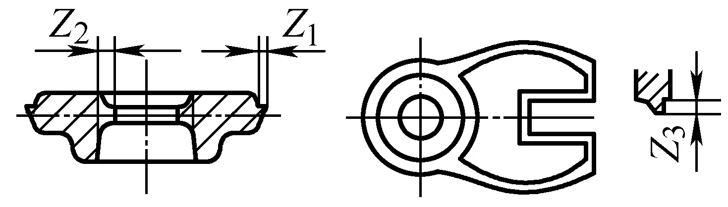 | Burrs around:Z 1 Burrs in inner hole:Z 2 Burrs at the fork:Z 3 | Z1=0.5~1.0 Z2 = 1.0 ~ 2.0 Z3 = 1.0 ~ 2.0 | Z1 = 0.7 to 1.5 Z2 = 1.5 ~ 2.0 Z3 = 1.5 ~ 2.0 | Z1 = 1.0 ~ 2.0 Z2 = 2.0 ~ 3.0 |
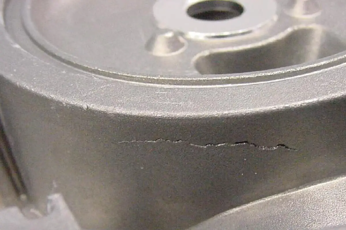
| 2 | 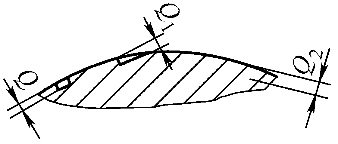 | Surface defect depth ①Unmachined surface (see values on the right side of this table) ②Machined surface not greater than 1/2 of the actual margin Q – Scale pits or dents Q 1 – Bent Texture Q 2 – Crack | 0.5 ~1.0 | 0. 75 ~1.5 | 1.0 ~2.0 |
| 3 | 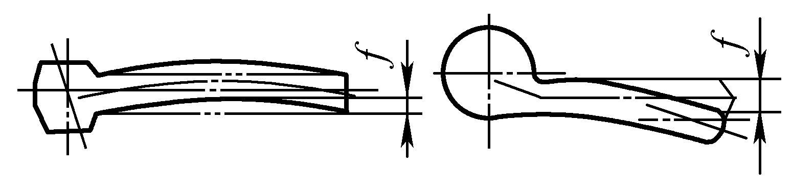 | Bending: f (but not greater than 1/2 of the rod margin) | 0.8 ~1.0 | 0.8 ~1.5 | 1.0 ~2.0 |
| 4 | 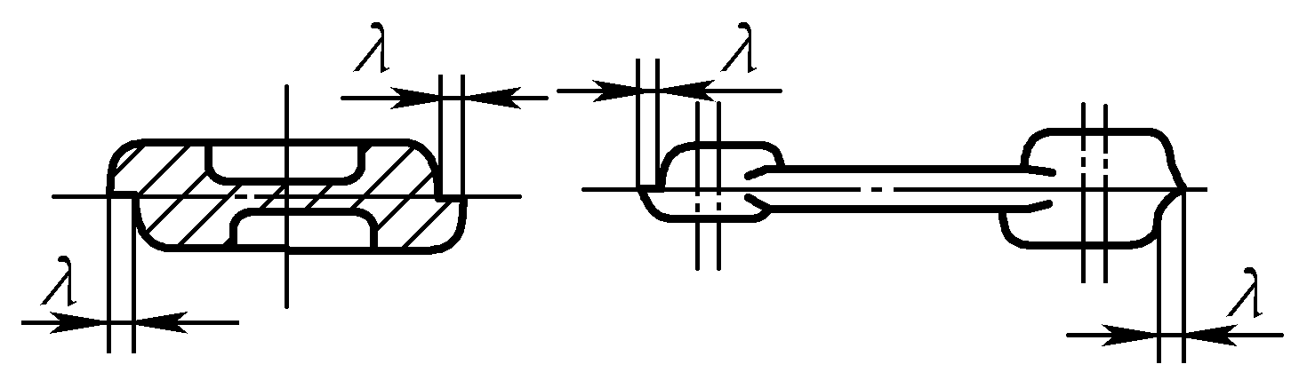 | Error: λ | 0.8 ~1. 0 | 0.8 ~1.5 | 1.0 ~2.0 |
| 5 | 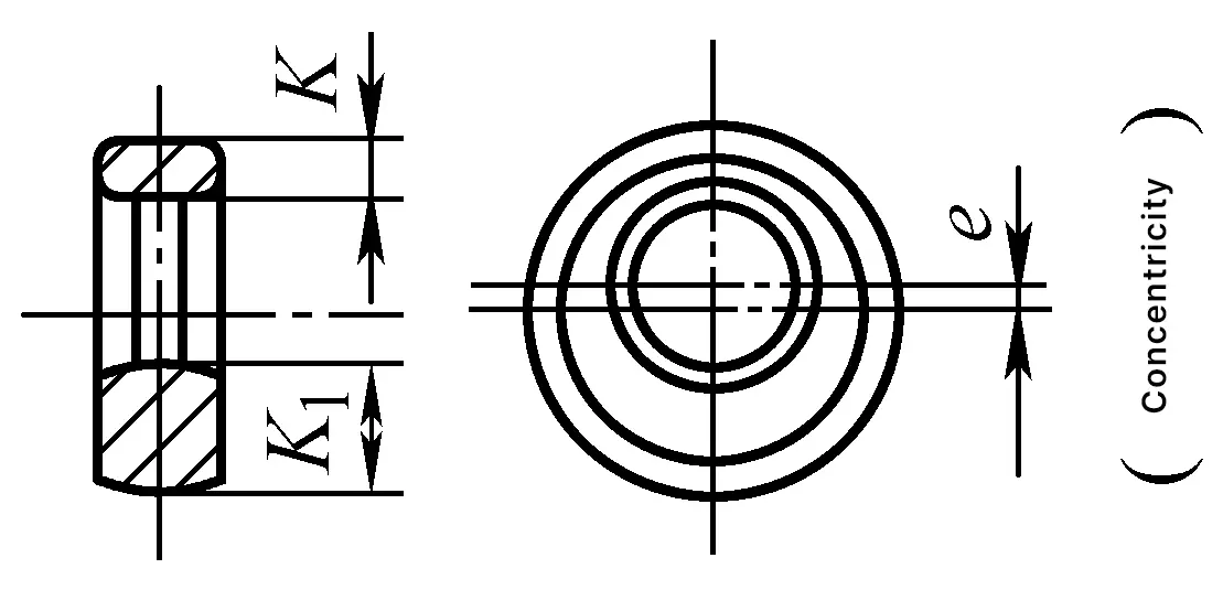 | Wall thickness difference: K-K 1 = 2e (but not greater than 1/2 allowance) | 0.8 ~1.0 | 1.5 ~2.0 | 2.5 ~3.0 |
| 6 | 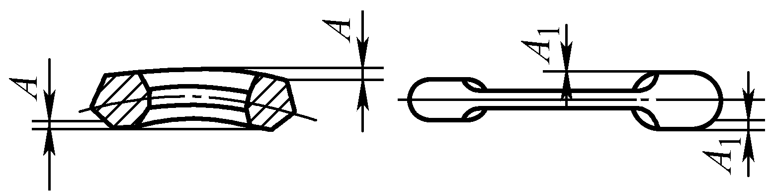 | Flatness: A (but not greater than 1/2 allowance) | 0.5 ~1.0 | 0.8 ~1.5 | 1.0 ~2.0 |
The purpose of forging quality inspection is to ensure that the quality of forgings meets the technical standards of the forgings. Common forging technical standards are shown in Table 4. The content of forging quality inspection includes: inspection of forging geometry and size, surface quality inspection, internal quality inspection, mechanical property inspection, and chemical composition inspection, etc.
Table 4 Common Forging Technical Standards
| Standard Number | Standard Name |
| GB/T 8541—2012 | Forging Terminology |
| GB/T 12361—2003 | General Technical Conditions for Steel Forgings |
| GB/T 12362—2003 | Steel die forgings tolerances and machining allowances |
| GB/T 12363—2005 | Classification of forging functions |
| GB/T 13320—2007 | Metallographic structure grading chart and evaluation method for steel die forgings |
| GB/T 21469—2008 | Machining allowances and tolerances for hammer steel free forgings – General requirements |
| GB/T 21470—2008 | Machining allowances and tolerances for hammer steel free forgings – Discs, columns, rings, and cylinders |
| GB/T 21471—2008 | Machining allowances and tolerances for hammer steel free forgings – Shafts |
| GB/T 16923—2008 | Normalizing and annealing of steel parts |
| GB/T 16924—2008 | Quenching and tempering of steel parts |
| JB/T 4290—2011 | Technical conditions for high-speed tool steel forgings |
| JB/T 4385.1—1999 | General technical conditions for hammer free forgings |
| JB/T 4385.2—1999 | Free forging on hammer Complexity classification and conversion coefficient |
| JB/T 9174—1999 | Material consumption process quota for die forgings Compilation method |
| JB/T 9177—1999 | Structural elements of steel die forgings |
| JB/T 9178.1—1999 | General technical conditions for free forging on hydraulic press |
| JB/T 9178.2—1999 | Complexity classification and conversion coefficient for free forging on hydraulic press |
| JB/T 9179.1~8—2013 | Machining allowance and tolerance for free forging on hydraulic press |
| JB/T 9180.1—2014 | Steel cold extrusion parts Part 1: Tolerances |
| JB/T 9180.2—2014 | Steel cold extrusion parts Part 2: General technical conditions |
| JB/T 9181—1999 | Structural design specifications for precision hot forging of straight bevel gears |
| JB/T 4201—1999 | Technical conditions for precision hot forging of straight bevel gears |
| JB/T 8421—1996 | General rules for inspection of steel forgings |
The specific inspection items and requirements for forgings vary with the grade of the forging. The grade of the forging is classified according to the part’s stress conditions, working conditions, importance, material type, and metallurgical process. The classification of forging grades varies across industrial sectors, with some departments dividing forgings into three levels, and others into four or five levels.
Table 5 classifies forgings into three levels and indicates the inspection items for each level. Table 6 is the standard for test methods for each inspection item of forgings. For some forgings with special requirements, inspection must also be conducted in accordance with the specifications in the dedicated technical conditions document.
Table 5 Forging grades and inspection items
| Inspection items | Grade | Remarks | |||
| I | II | III | |||
| Quantity inspected per batch | |||||
| Material grade | 100% | 100% | 100% | ||
| Surface quality | 100% | 100% | 100% | ||
| Geometric dimensions | 100% | 100% | 100% | Vertical dimensions and misalignment are checked 100%, other dimensions are spot-checked as necessary | |
| Hardness | Steel forgings | 10% | 10% | 10% | |
| Non-ferrous alloy forgings | 100% | 100% | 100% | Copper alloys, 3A21 not checked | |
| Mechanical properties | Draw 1 piece per melt batch, special surplus material is 100% | Draw 1~2 pieces per melt batch | Aluminum, magnesium parts carry test bars with each heat treatment furnace | Steel, aluminum, and magnesium parts are not subject to impact toughness inspection | |
| Low magnification structure | Draw 1 piece per melt batch | Draw 1 piece per melt batch | |||
| High magnification structure | The remainder of non-ferrous alloy forgings is 100% | Draw 1 piece from non-ferrous alloy forgings | Non-ferrous alloy forgings not subjected to quenching treatment are not inspected | ||
| Fracture | The remainder of steel forgings is 100%, draw 1 piece from non-ferrous alloy forgings | When there are no specific regulations, take the fracture from the low magnification test piece | |||
Table 6 Test methods standards for various inspection items of forgings
| Inspection items | Test method standards |
| Chemical composition | GB/T 222—2006 GB/T 223.3—1988, etc. |
| Mechanical properties (tensile, impact) | GB/T 229—2007 GB/T 228.1—2010 |
| High temperature creep | GB/T 2039—2012 |
| Fatigue performance | GB/T 4337—2008 GB/T 3075—2008 |
| Brinell hardness | GB/T 231.1—2009 |
| Rockwell hardness | GB/T 230.1—2009 |
| Low magnification structure | GB/T 1979—2001 GB/T 4297—2004 GB/T 3246.2—2012 |
| Fracture grain size | GB/T 1814—1979 GB/T 6394—2002 |
| Decarburized layer non-metallic inclusions | GB/T 224—2008 GB/T 10561—2005 |
| High magnification structure | GB/T 13320—2007 |
| Intergranular corrosion | GB/T 4334—2008 GB/T 7998—2005 |
| Bend test | GB/T 232—2010 |
The inspection content of forging geometry and dimensions includes:
The geometric shape and size of the forging can be measured with general measuring tools such as calipers, micrometers, and vernier calipers. In mass production, special measuring tools along with go/no-go gauges, plug gauges, and templates can be used for inspection. For forgings with complex shapes and multiple inspection areas or items, specially made special instruments or templates can be used for inspection.
Table 7 Forging Surface Quality Inspection Methods
| No. | Inspection Method | Characteristics and Uses |
| 1 | Visual Inspection | This is the most common and frequently used method for inspecting the surface quality of forgings. The inspector carefully observes the surface of the forging with the naked eye for defects such as cracks, folds, indentations, spots, and surface overheating. To facilitate the observation of defects, visual inspection is usually carried out after removing the oxide skin through pickling, sandblasting, or tumbling. |
| 2 | Magnetic Particle Inspection | Magnetic particle inspection, also known as magnetic particle testing or magnetic flaw detection, can find fine cracks and surface defects such as cracks hidden beneath the surface that are not visible to the naked eye. However, it can only be used on magnetic materials such as carbon steel, tool steel, and alloy structural steel, and the surface of the forging must be smooth and flat. |
| 3 | Fluorescence detection | For surface defects of forgings made of non-ferromagnetic materials, such as non-ferrous alloys, high-temperature alloys, stainless steel, etc., fluorescence detection can be used. Fluorescence detection is not limited by whether the material is magnetic or non-magnetic |
| 4 | Dye penetrant inspection | This method is not limited by whether the material is magnetic or non-magnetic. It uses a highly penetrative oil with color to penetrate into the surface defects of the forging, and uses an absorbent to draw it out, allowing the surface defects to be seen with the naked eye under ordinary light |
Table 8 Methods for inspecting the internal quality of forgings
| No. | Inspection method | Features and applications |
| 1 | Ultrasonic testing | Strong penetration; the equipment is nimble, easy to carry, and simple to operate; it can accurately detect defects such as cracks, inclusions, shrinkage cavities, and pores; it can inspect forgings from one side, which is quite convenient for large forgings. Mainly used for important large forgings |
| 2 | Low magnification inspection | Low magnification inspection involves using the naked eye or a magnifying glass of 10 to 30 times magnification to check for defects on the cross-section of forgings. Common inspection methods include: etching, fracture, and sulfprint. The etching method is generally used for defects such as flow lines, dendrites, residual shrinkage cavities, voids, slag inclusions, and cracks. Fracture inspection is used for defects such as overheating, overburning, white spots, delamination, and the appearance of naphthalene and stone-like fractures. The distribution of sulfides is checked using the sulfprint method |
| 3 | High magnification inspection | High magnification inspection is the examination of the internal structure (or fracture surface) and micro defects of forgings under various microscopes. There are three types of microscopes used for high magnification inspection: ordinary full-phase microscope, transmission electron microscope, and scanning electron microscope. In actual production, general inspection items, such as examining the grain size of structural steel, inclusions, decarburization, and the distribution of carbides in tool steel, are all conducted at 100 to 500 times magnification under an ordinary full-phase microscope |
Non-destructive testing can detect surface or internal defects of forgings without damaging them. Non-destructive testing is very suitable for important forgings with strict quality requirements, and a comparison of several common non-destructive testing methods is shown in Table 9.
Table 9 Comparison of several non-destructive testing methods
| Inspection method | Requirements for the sample | Detectable defects | Damage assessment method | Flaw detection conclusion | Advantages and disadvantages | |
| Ultrasonic testing | Material is not limited, steel thickness can reach up to 10m, surface must be smooth, shape must be simple, and single-sided detection is possible | Defects in any part can be detected with high sensitivity | Based on the indication of the ultrasonic signal | Defect location, depth, size, and distribution | Wide applicability, high sensitivity, easy operation, immediate availability of test results, harmless to the human body. But it can only be used for workpieces with simple shapes and low surface roughness, and cannot determine the nature of defects | |
| X-ray inspection | No limit on materials, no limit on shape, no special processing requirements, thickness cannot be too great | The defect location should be near the surface or inside | Based on photographic film or fluorescent screen display | Defect location, shape, size, and distribution | High perspective sensitivity, can keep permanent records, not limited by materials and shapes But it is expensive, the equipment is bulky, cannot detect planar defects, and is harmful to the human body | |
| Magnetic particle inspection | Limited to ferromagnetic materials, surface roughness Ra >1.6μm, test piece size is limited by equipment, thickness is in principle unlimited | Surface and near-surface minor defects | According to the accumulation of magnetic particles | The position, shape, and length of defects | High speed, high sensitivity, simple equipment, and convenient operation But it cannot inspect non-ferromagnetic materials, cannot inspect internal defects, nor determine the depth of defects | |
| Penetration testing | Fluorescence | Various metal materials, surface roughness Ra >1.6μm, no thickness limit | Must be micro defects extending to the surface | Observe the accumulation of powder under ultraviolet light | The location, shape, and length of surface defects | Not limited by materials, the equipment is simple, and the operation is convenient. However, it can only detect defects exposed on the surface, and ultraviolet light is harmful to human vision |
| Coloring | Various materials, surface roughness Ra >1.6μm, no thickness limit | Surface defects | Directly judge from the agglomeration of the powder | The location, shape, and length of surface defects | Not limited by materials, no special equipment required, simple operation. But it can only detect surface defects, low sensitivity, slow speed | |
| Eddy current testing | Limited to metal materials, smooth surface, simple shape | Surface and near-surface streaks | According to electrical signal indication | Determine the presence and approximate size of surface defects | The equipment is simple and compact, easy to carry. Slow speed, unable to determine the nature and depth of defects | |
Table 10 Forging mechanical property inspection methods
| No. | Inspection method | Characteristics and applications |
| 1 | Hardness test | The hardness test is the simplest and most commonly used method to judge the mechanical properties of forgings in production. The common hardness test methods for forgings include Brinell hardness, Rockwell hardness, and Vickers hardness, especially Brinell hardness is the most used. The purpose of testing hardness is to determine whether the forging has appropriate machinability, whether the surface is decarburized, and to roughly understand the internal structure of the forging. |
| 2 | Tensile test | Through the room temperature tensile test, the tensile strength R m , yield strength R eL and R eH (or specified plastic elongation strength R p0.2 etc.), elongation after fracture A, and reduction of area Z of the forging can be determined. |
| 3 | Impact test | Through the impact test, the impact absorption energy KV or KU, etc., of the forging can be determined. |
In order to ensure that the forging has the dimensional accuracy and mechanical performance requirements specified in the forging drawing, it is necessary to control the quality of the forging, that is, to control the entire production process from raw material to post-forging heat treatment, to ensure the stability of production quality and the consistency of the product.
Forging quality control includes: incoming inspection (raw materials), intermediate inspection (semi-finished products), final inspection (finished forgings), and control of production means such as tooling, equipment, and measuring instruments adjustment, inspection, and measurement tools.
The pre-forging heating process and post-forging heat treatment process are special processes, whose quality characteristics cannot be precisely measured or economically measured, mainly relying on strict process parameter control to ensure quality.
Forging quality control is shown in Table 11.
Table 11 Quality Control of Forgings
| No. | Item | Key Points of Quality Control |
| 1 | Quality Control of Raw Materials | 1) Verify the material’s mill test certificate with the material standard 2) Check if the material’s identification is correct to avoid mixing materials 3) Check material specifications 4) Inspect the surface quality of materials for defects such as cracks and scars 5) Random inspection of chemical composition 6) Use rapid spectrometer, spark identification, etc., to inspect and avoid material mixing |
| 2 | Mold quality control | 1) Verify the mold’s quality assurance certificate or manufacturing inspection report (including non-destructive testing) 2) Mold inspection (re-inspection), including shape, size, hardness 3) Adjust the mold on the machine tool, and inspect the sample marking 4) Mold repair |
| 3 | Heating quality control | 1) Use a three-way temperature sorting device for heating or use an infrared thermometer to detect the heating temperature 2) Use rapid heating when heating with a coal stove or oil furnace |
| 4 | Forging process quality control | 1) First article inspection 2) Intermediate workers self-inspect, inspectors re-inspect, and fill in records 3) Equip with necessary inspection and measuring tools |
| 5 | Heat treatment quality control | 1) Strictly control heat treatment process parameters and save records 2) Intermediate workers self-check hardness, inspectors re-check hardness, and record 3) When necessary, use a magnetic hardness sorter or hardness tester for 100% hardness inspection 4) When necessary, use the corresponding non-destructive testing methods to check for cracks |
| 6 | Product identification and traceability control | 1) Starting from when the raw materials enter the workshop, they are managed with tags 2) Tag management during the processing, indicating part number, name, material grade, specifications, material batch number, operator, inspector, etc., and following the forging through each process until it reaches the machining unit 3) When necessary, print the mold serial number, material batch number, and other marks on the forging |
Table 12 Methods for correcting defects in forgings
| No. | Type of defect | Correction method |
| 1 | Burrs, splits, folds | Use grinding wheel polishing, pneumatic shovel removal, or rotary file polishing methods for correction |
| 2 | For parts that are not too severe or not too large unfilled | Can be re-forged in a new forging mold, or corrected by welding (fusion) method |
| 3 | For forgings that are insufficiently forged | Can be pre-processed in the machining workshop for correction. Such insufficiently forged forgings should not be re-forged, as this may cause new oxide skin to press into the forging and become an irreparable waste product. Sometimes grinding can be used for correction. For unimportant forgings, they can be reheated once to correct by turning the excess metal into oxide skin, finally adding shot blasting treatment |
| 4 | Error | The correction method for errors is to reforge once. If the error is severe, it cannot be corrected; if the error is not severe, grinding can also be used for correction |
| 5 | Bending deformation | Correction can be made by heating to the forging trimming temperature or by using a press or friction press in a cold state |
| 6 | Overheating | For overheated forgings, normalization can be used for correction |
| 7 | Forging hardness not qualified | When the hardness is too high, it can be corrected by re-tempering; when the hardness is too low, it can be corrected by re-quenching and tempering |
| 8 | For forgings that are overburnt, quench cracked, severely folded, or severely out of dimension | Should be treated as irreparable forgings, scrapped, and not corrected |