The manufacturability of bent components refers to their adaptability to stamping processes. Conducting a structural manufacturability analysis on bent parts is essential for determining the difficulty of the bending formation, devising stamping strategies, and designing molds.
Well-manufactured bent components not only ensure high quality but also simplify processes and tooling. The manufacturability of bent parts is primarily reflected in the following aspects:
Minimum Bending Radius
When the relative bending radius (r/t) of a bent component is reduced to a certain extent, the tensile strain on the outer surface fibers may exceed the material’s allowable limit, causing cracks or fractures.
Therefore, there is a restriction on the minimum bending radius. This is the smallest internal corner radius that can be achieved without damaging the outer surface fibers of the blank, known as the minimum bending radius (rmin). Correspondingly, rmin/t is referred to as the minimum relative bending radius.
Factors affecting the minimum bending radius include:
(1) Mechanical properties of the material
The better the plasticity of the material, the higher its plasticity index, and the smaller the minimum bending radius.
(2) The relationship between the material’s fiber direction and the bending line
Rolled sheet materials are anisotropic, with plasticity indices along the fiber direction being higher than those perpendicular to it. Consequently, if the bending line is perpendicular to the material’s fiber direction, the value of rmin/t is smaller than when the bending line is parallel to the fiber direction.
When bending parts with a small r/t, the bending line should ideally be perpendicular to the fiber direction of the sheet material to enhance the degree of deformation and prevent the outer fibers from tearing. For components requiring multi-directional bending, the bending line can be set at a fixed angle to the fiber direction of the material. The relationship between the bending line and the fiber direction of the material is illustrated in Figure 3-4.
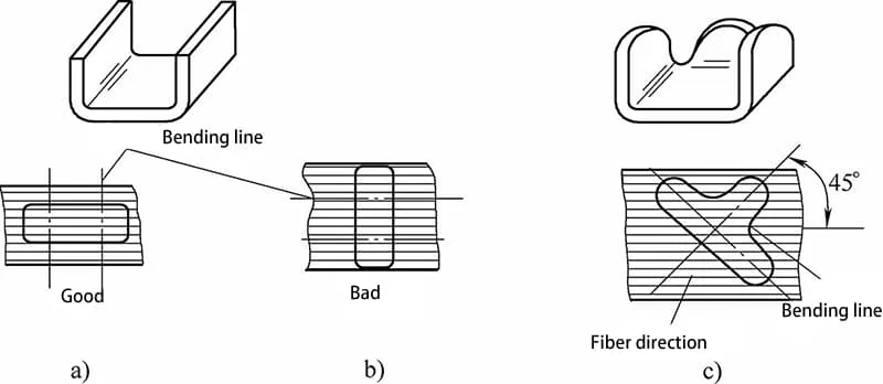
a) The bend line is perpendicular to the grain of the sheet metal.
b) The bend line is parallel to the grain of the sheet metal.
c) The bend line is at a specific angle to the grain of the sheet metal.
(3) Surface Quality and Blanks Cross-Sectional Quality of Sheet Metal
If the surface of the blank has scratches, cracks, or if the side (sheared or punched cross-section) has burrs, notches, and signs of cold work hardening, it is prone to cracking during bending.
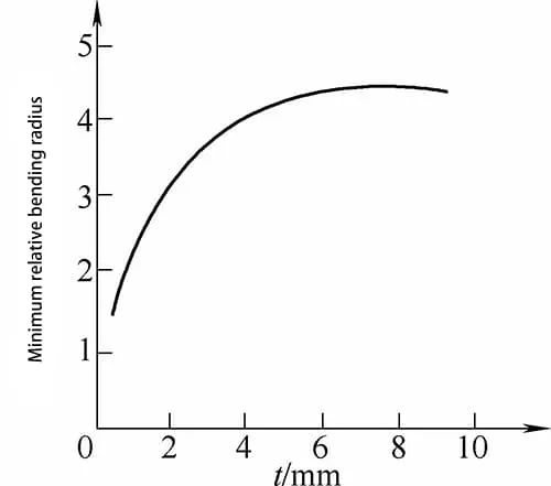
Therefore, sheet metal with poor surface and cross-sectional quality will have a larger minimum relative bending radius rmin/t, as shown in Figure 3-5. For the bending of thick plates, to prevent cracking, it is best to place the side with punching burrs on the inside of the bend, as illustrated in Figure 3-6.
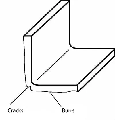
(The burr facing outward is prone to cracking)
(4) Thickness of Sheet Metal
Generally, the thicker the sheet metal, the larger the minimum bending radius. This is mainly because the tangential strain in the deformation zone changes linearly in the thickness direction, being maximal on the surface and zero at the neutral layer. When the thickness of the sheet metal is small, the gradient of the tangential strain changes sharply, rapidly decreasing from its maximum value to zero.
The metal adjacent to the outer surface, where the tangential deformation is greatest, can act to prevent local unstable plastic deformation of the surface metal. Thus, in such cases, larger deformations and smaller minimum bending radii can be achieved. In other words, the thinner the sheet metal, the smaller the r/t ratio.
Table 3-1 lists the minimum bend radius values, while Table 3-2 details the minimum bend radius for tubular workpieces.
Table 3-1: Minimum Bending Radius
| Materials | Annealed condition | Cold-worked hardened condition | ||
| The position of the bend line. | ||||
| Vertical fibers | Parallel fibers | Vertical fibers | Parallel fibers | |
| 08, 10, Q195, Q215-A | 0. 1t | 0.4t | 0. 4t | 0.8t |
| 15, 20, Q235-A | 0. 1t | 0.5t | 0.5t | 1. 0t |
| 45, 50, Q275 | 0.5t | 1. 0t | 1. 0t | 1.7t |
| 60Mn, T8 | 1. 2t | 2. 0t | 2. 01 | 3.0t |
| Pure Copper | 0. 1t | 0.35t | 1. 0t | 2. 0t |
| Soft Brass | 0. 1t | 0.35t | 0.35t | 0.8t |
| Brass (Half-Hard) | 0. 1t | 0.35t | 0.5t | 1. 21 |
| Phosphor Copper | 一 | 一 | 1. 0t | 3.0t |
| Aluminum | 0. 1t | 0.2t | 0.3t | 0.8t |
| Semi-Hard Aluminum | 1. 0t | 1.5t | 1. 5t | 2.5t |
| Hard Aluminum | 2. 0 | 3. 0t | 3. 0t | 4. 0t |
Note:
– When the bending line is at an angle to the knurling, select a value that corresponds to the angle.
– The values in the table are suitable for bends with the burr on the inside of the bend; when the burr is on the outside, increase the bending radius accordingly.
– For bending unannealed blanks after punching or shearing, treat the material as hardened metal.
– “t” represents the thickness of the material.
Table 3-2: Minimum Bend Radius for Tubing
| Wall thickness | Minimum Bend Radius R | Wall thickness | Minimum Bending Radius R |
| 0.02d | 4 times the material thickness | 0.10d | 3D |
| 0.05d | 3.6 times the material thickness | 0.15d | 2D |
Straight Edge Height
For a right-angle bend (refer to Figure 3-7a), the minimum height of the straight edge of the bent part should be h=2t. When the bent part has a beveled edge (see Figure 3-7b), the minimum height of the side edge should be hmin=(2~4)t or 1.5t+r.
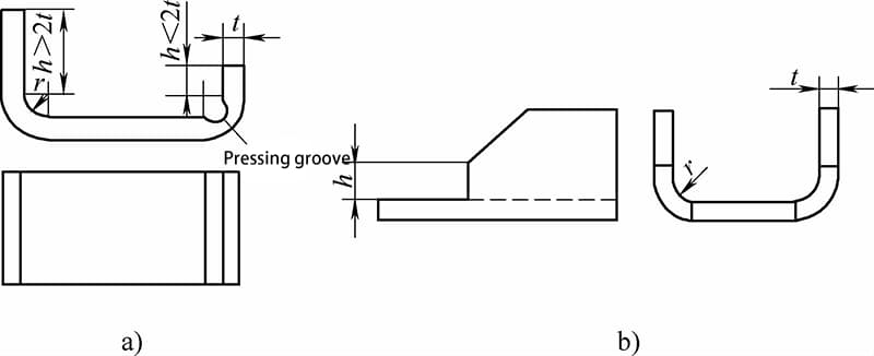
a) Height of the Straight Edge of the Bent Component
b) Height of the Side Edge of the Bent Component
Hole Edge Distance
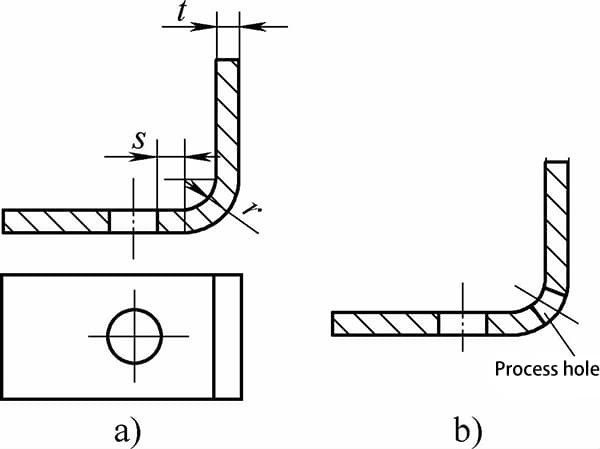
When a hole is too close to the bend line, deformation can occur during the bending process. Therefore, it is essential to position the hole outside of the deformation zone, as illustrated in Figure 3-8. The distance from the edge of the hole to the center of the bending radius, denoted as “s,” must meet the following criteria:
- For material thickness “t” less than 2mm, “s” should be greater than or equal to “t”.
- For material thickness “t” of 2mm or greater, “s” should be greater than or equal to twice the thickness, or “2t”.
Symmetry in Shape and Size
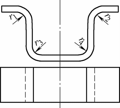
The shape and size of bent components should be as symmetrical as possible. As depicted in Figure 3-9, it is preferable for the part’s fillet radii to satisfy the condition where r1 = r2 and r3 = r4.
