I. Manual Bending Forming Process
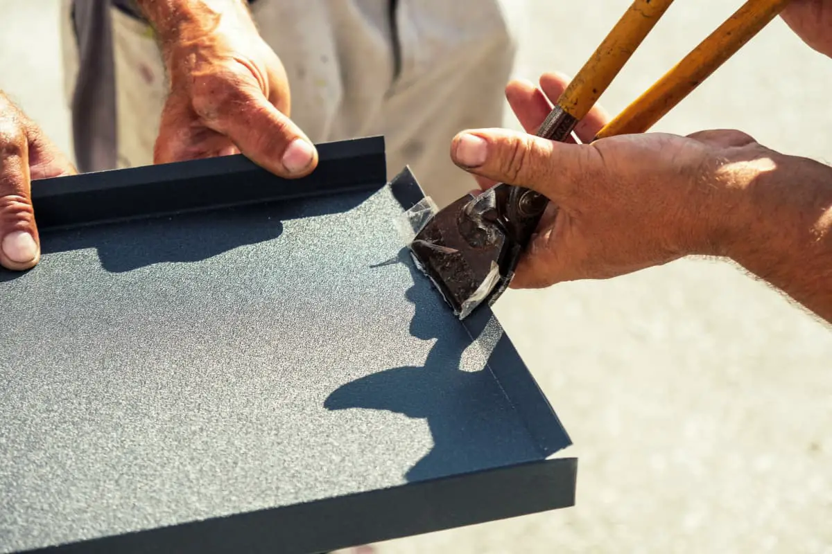
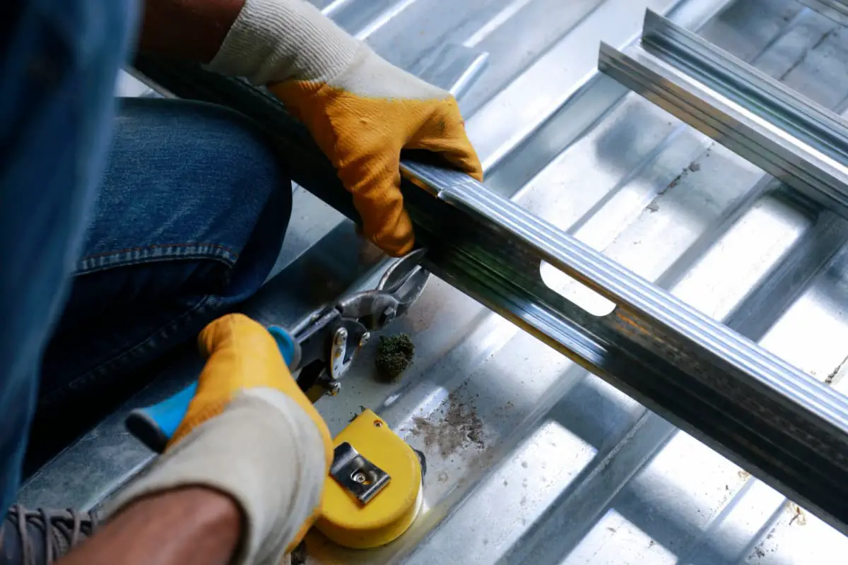
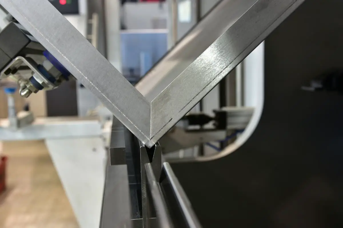
The processing method of bending sheet metal or profiles using simple manual machinery and tools is called manual bending forming. Manual bending forming does not require high processing conditions and is very flexible in operation. However, it involves high labor intensity, low precision of bent parts, and low productivity. Therefore, it is often used for bending processing when there are very few parts. In addition, it is also commonly used for manual bending when equipment conditions are lacking or mechanical forming is difficult.
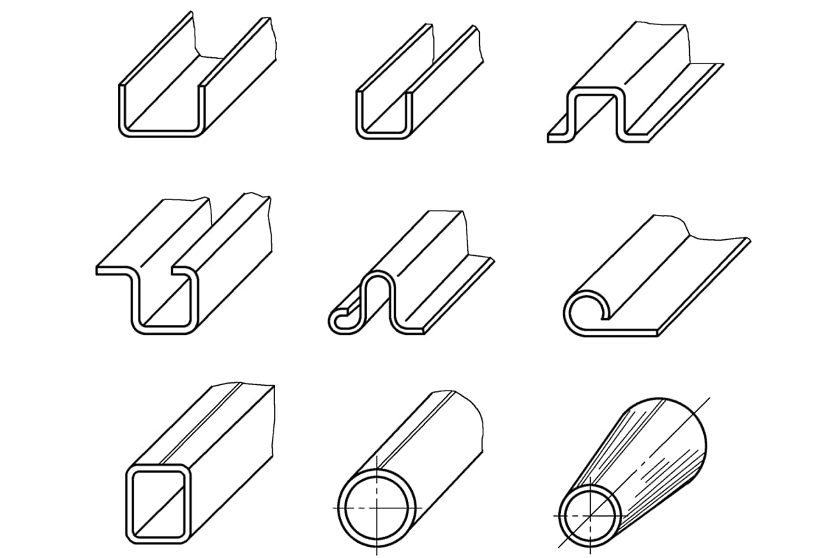
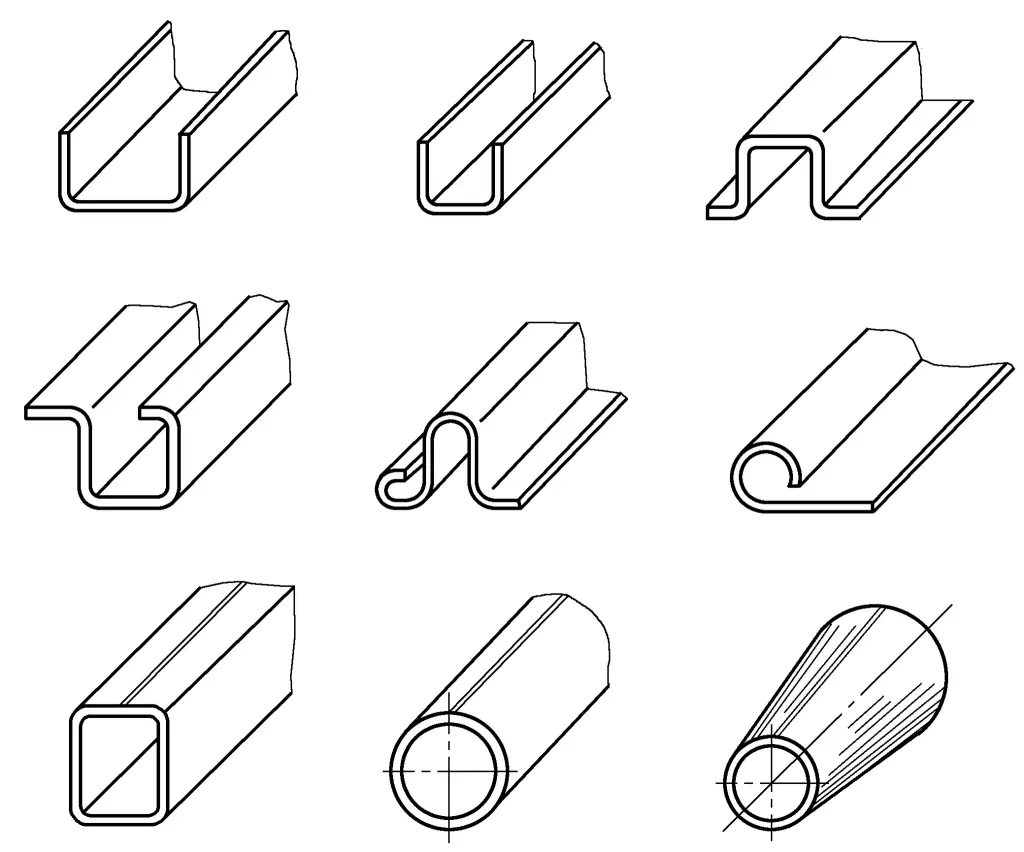
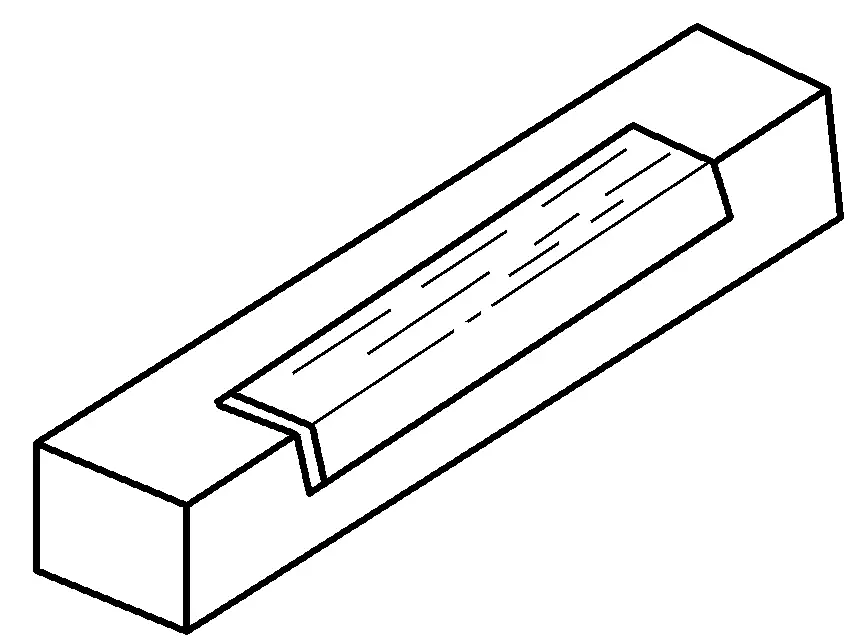
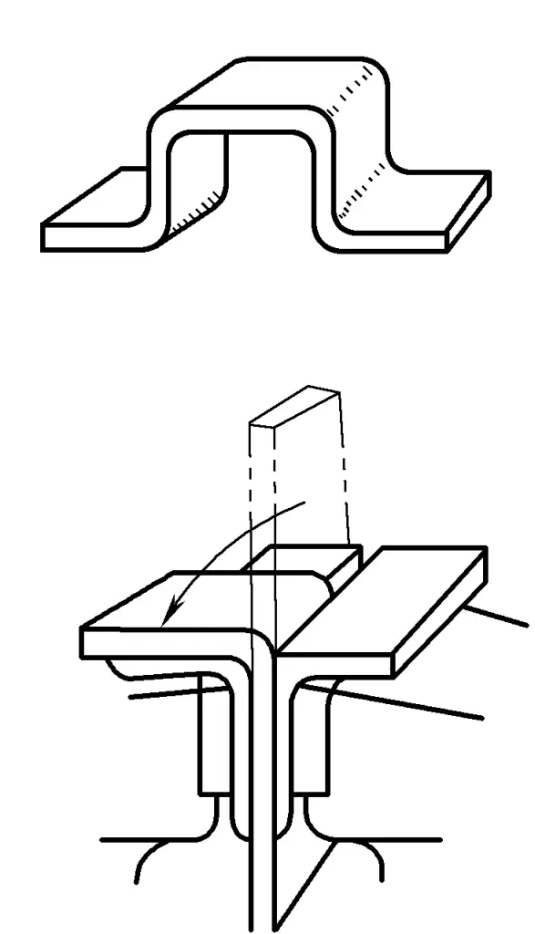
Figure 4-1 shows various typical bent sheet metal parts.
1. Bending of angular parts
(1) Bending with a square iron
First, draw the bending line on the sheet, then align the bending line with the corner of the square iron, hold the sheet with the left hand, and use a wooden mallet with the right hand to bend both ends to a certain angle for positioning, then bend it completely into shape, as shown in Figure 4-2.
(2) Bending with angle iron
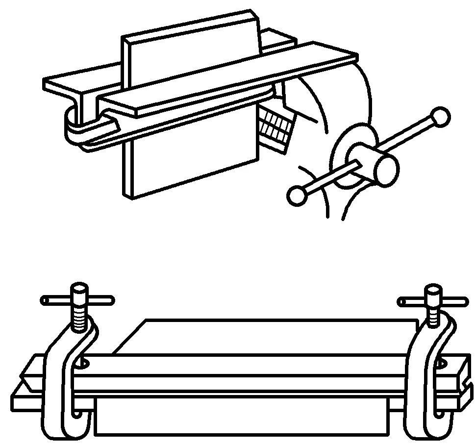
When bending wide and thick sheets, you can clamp the sheet between two angle irons on a bench vise, or use a bow-shaped clamp to hold the sheet, then bend it with a wooden mallet as shown in Figure 4-3.
(3) Bending with a bench vise
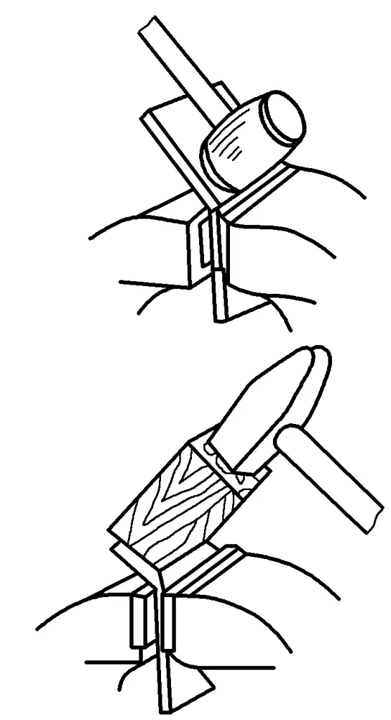
First, draw a line at the bending corner of the sheet, align the line with the jaws of the vise and clamp it, then use a wooden mallet to hammer along the base of the sheet. When the protruding length of the sheet end is short, you can place a block of wood at the bending corner and use a wooden mallet for indirect hammering to bend it, as shown in Figure 4-4.
2. Bending of U-shaped parts
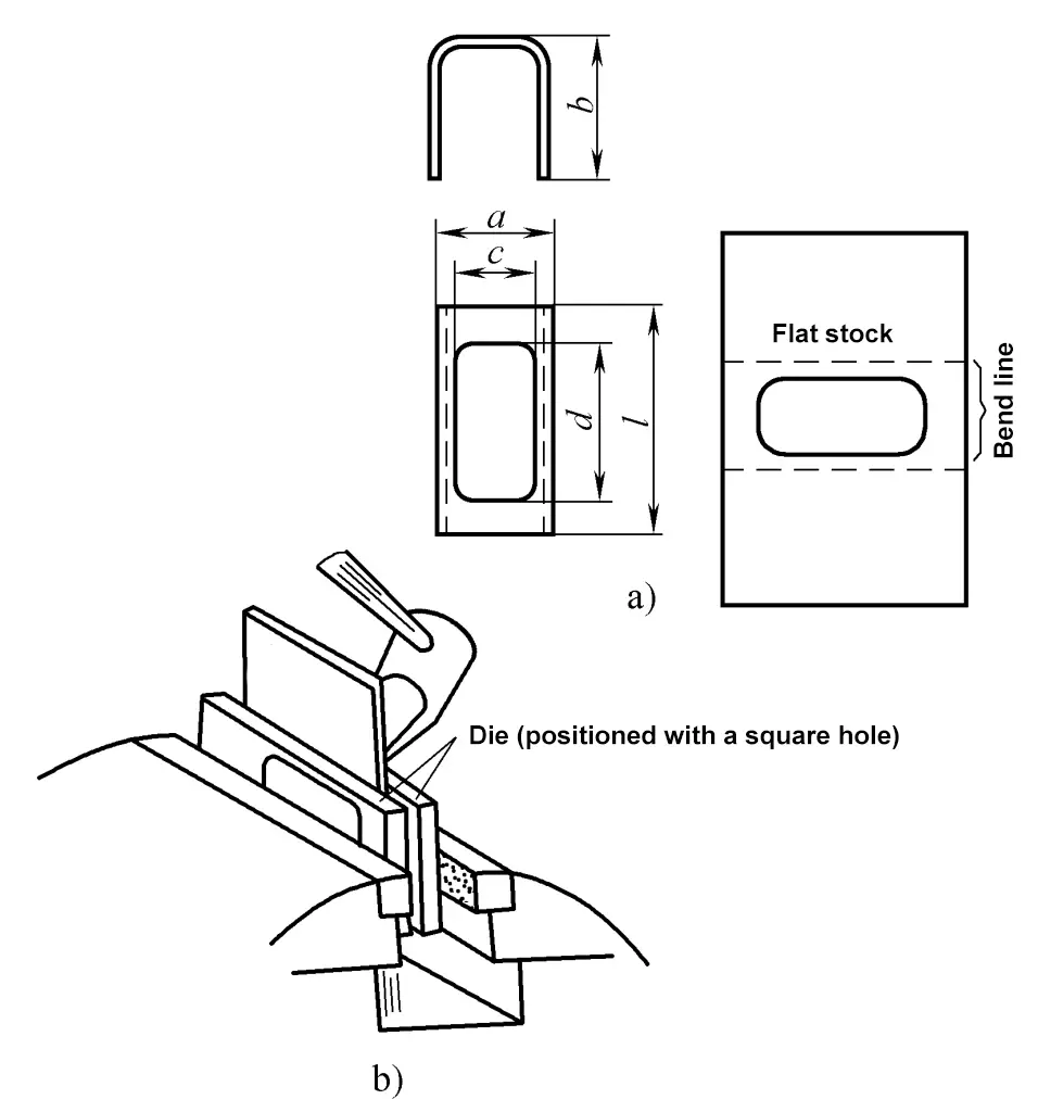
As shown in Figure 4-5a, the part to be bent and the unfolded blank are shown. If holes are drilled on the blank before bending, since the dimensions c and a are close, the distance between the bending line and the inner edge of the hole is very small, which increases the difficulty of bending. Therefore, a mold can be used to clamp it on the bench vise, using the square hole on the blank for positioning, as shown in Figure 4-5b, and then bend it by hammering with a wooden mallet.
3. Folding U-shaped parts bending
1) Draw four bending lines at the corners of the blank as a reference for bending, clamp the blank in the bench vise, and bend one of the middle corners, as shown in Figure 4-6.
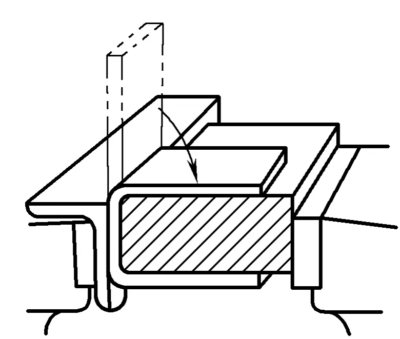
2) Clamp the blank on the bench vise with a shim, bend another corner, the thickness of the shim should be less than the distance between the two corners, as shown in Figure 4-7.
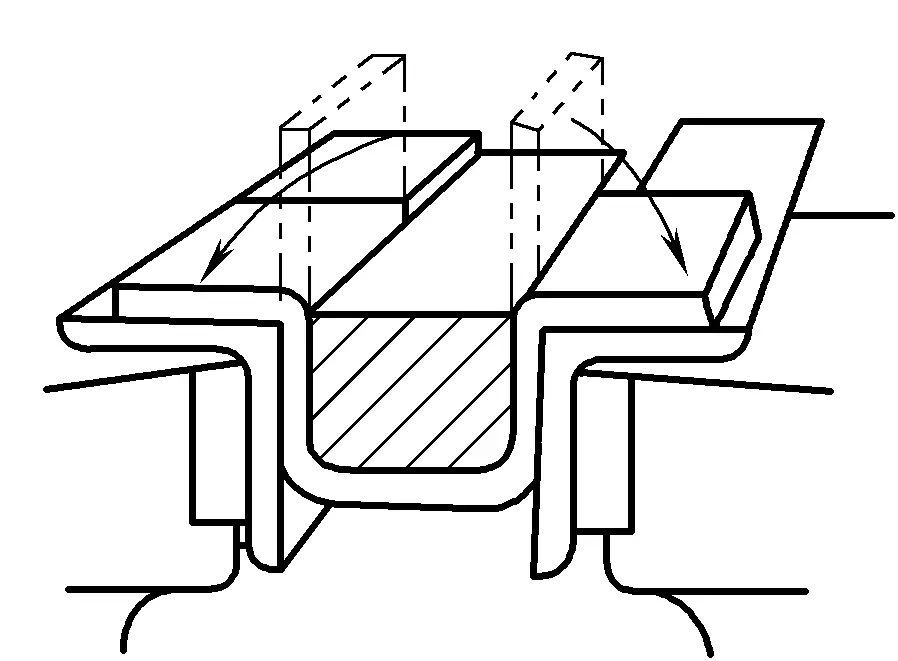
3) Use another shim to bend the last two corners, as shown in Figure 4-8.
4. Cylindrical surface bending
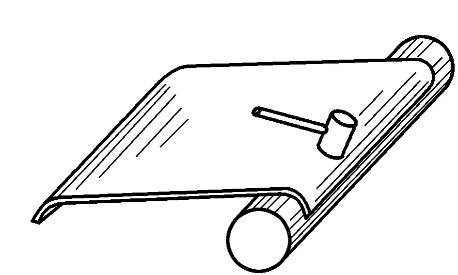
1) Draw lines parallel to the bending line on the sheet metal as a reference for hammering when rounding; use round steel or a mandrel to bend both ends of the sheet metal so that the radius of curvature is equal to or slightly less than the required bending radius. As shown in Figure 4-9.
2) Place the bent ends of the sheet metal on channel steel or beside the rail, and hammer with a shaped hammer, bending from both ends towards the middle. As shown in Figure 4-10.
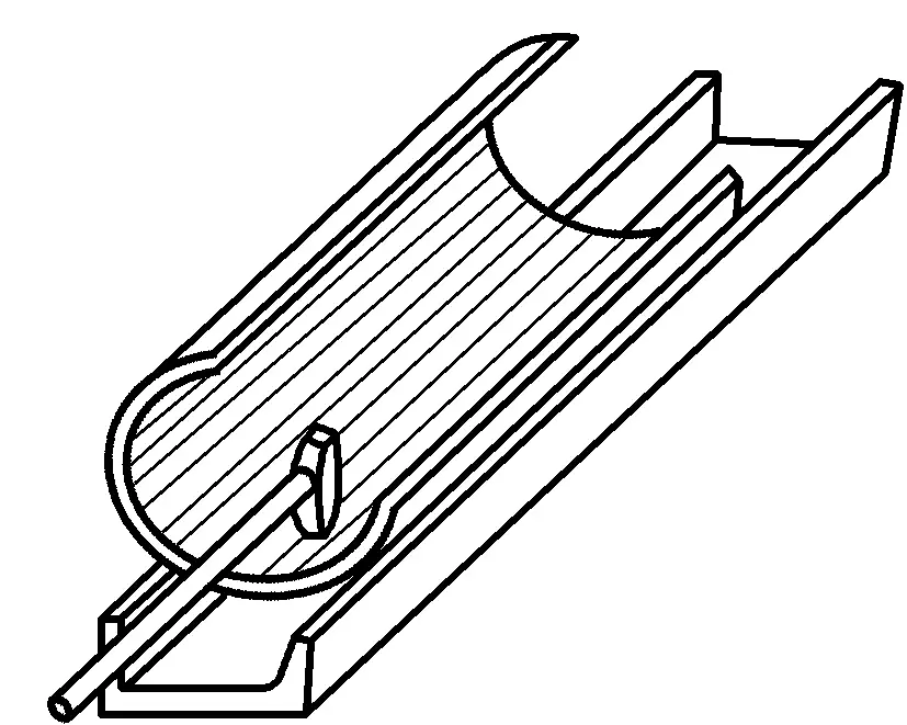
3) Fit the cylinder over the mandrel for rounding. As shown in Figure 4-11.
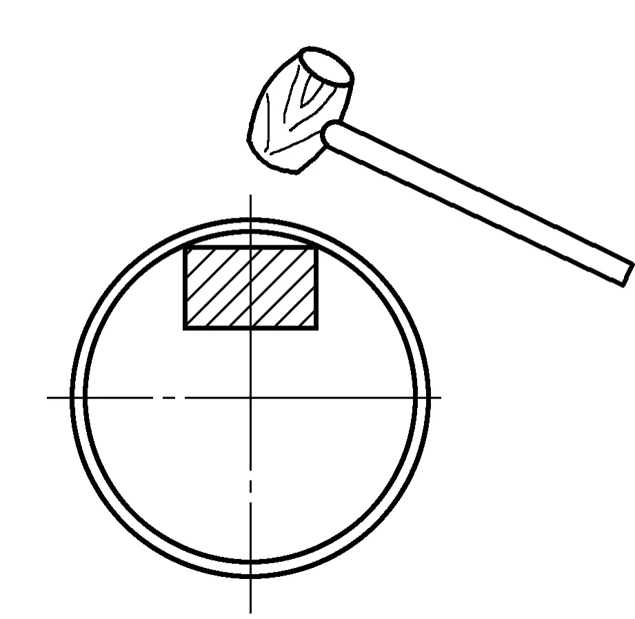
5. Conical surface bending
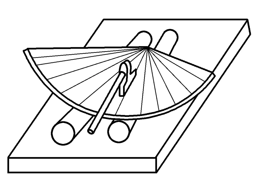
First draw radial bending lines on the sheet metal, then place the sheet metal on two round steels, and use a shaped hammer to hammer along the axis of the sheet metal, bending the ends first and then the middle. As shown in Figure 4-12.
II. Measures to Prevent Defects in Manual Bending Forming
During the bending process, defects such as bending cracks, springback, offset, and uneven bending edges often occur, as shown in Figure 4-13.
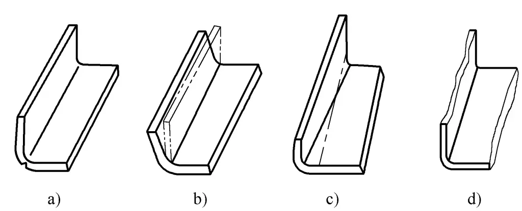
a) Bending cracks
b) Springback
c) Offset
d) Uneven bending edges
Among them, bending cracks are a more serious and common defect.
Bending cracks are greatly related to the minimum bending radius, mechanical properties of the material, surface quality of the sheet, quality of the sheared surface, and the direction of the material fibers. To prevent bending cracks, the following measures are often taken:
1) The bending radius should be greater than the minimum bending radius.
2) Use hot bending or anneal the sheet before bending to improve its plasticity.
3) Improve the quality of the shear surface or grind with a grinding wheel to eliminate stress concentration factors.
4) When laying out material, avoid having the bending line coincide with the direction of the material fibers.
5) The straight edge length of the bent parts should generally be no less than twice the thickness of the plate to ensure sufficient bending torque.
If less than twice, the straight edge can be appropriately extended, and cut off after bending.
6) To prevent distortion of the blank cross-section, the bending width of the sheet should generally be no less than three times the thickness of the plate. If less than three times, several parts should be bent together on the same sheet and then cut apart after bending.
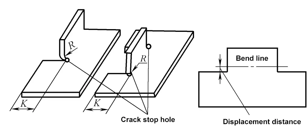
7) For parts that need to be bent into edges locally, to avoid bending cracks at the corners, pre-drill stop cracks holes, or move the bending line outwards by a certain distance, as shown in Figure 4-14.
8) When the radius of the bent part is small, to avoid bending cracks, pay attention to the surface quality of the blank, remove burrs and other surface defects from the shear surface, or place the poor-quality surface on the inside of the bend so that it is under compression and less likely to crack.
9) When heating is required for bending, the material heating temperature should be well controlled, and the surface temperature of the heating should be uniform. During bending, care should be taken not to let the mold temperature get too high to prevent deformation.
10) Bending forming operations should be carried out strictly in accordance with the relevant safety technical regulations of the enterprise.

