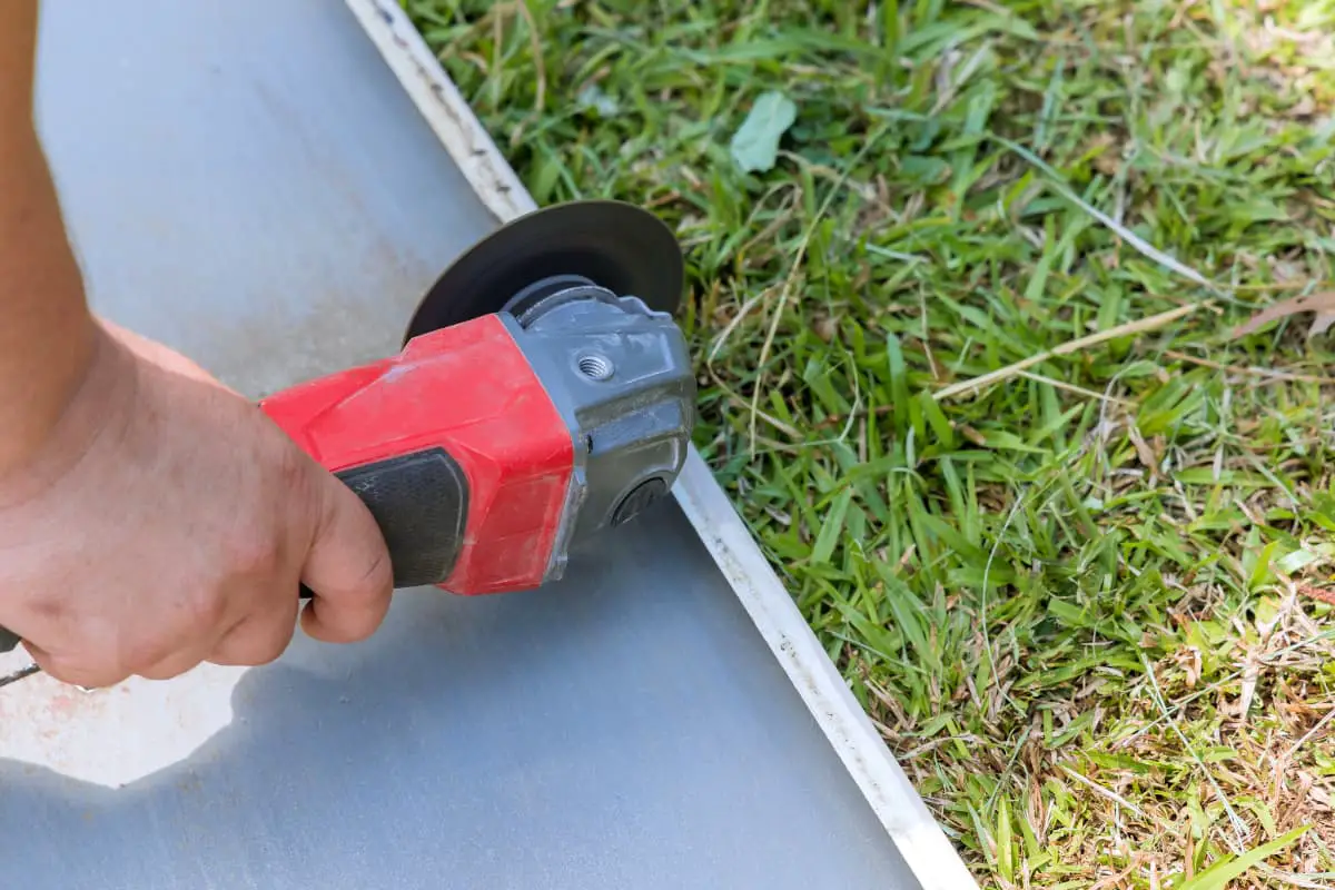
Shearing is a primary blanking method used in cold working, characterized by high production efficiency, relatively smooth cut surfaces, and the ability to cut sheet metal and various profiles.
1. Basic Knowledge of Shearing Processing
There are many methods of shearing processing, but the essence is to apply shearing force to the material through the upper and lower blades, causing the material to undergo shear deformation and finally fracture and separate. Therefore, to master shearing processing technology, it is necessary to understand the deformation and stress conditions of materials in shearing processing, the geometric shape requirements of the blades, and the calculation of shearing force.
Cold working often uses the oblique shear shown in Figure 3-42 in production. Here, only the shearing process, shearing force, and blade geometric parameters of the oblique shear are analyzed, and the method of calculating the shearing force is introduced.
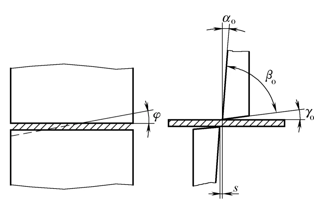
- γ o – Rake angle
- α o – Clearance angle
- β o – Wedge angle
- s – Blade clearance
- φ – Blade bevel angle
During shearing, the material is placed between the upper and lower blades, and the deformation and shearing process of the material under the action of shearing force is shown in Figure 3-43.
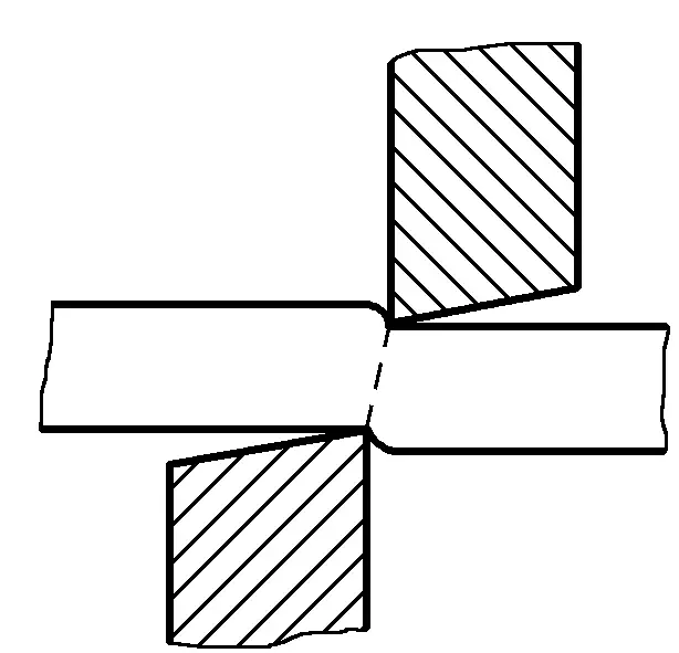
When the blade edge begins to contact the material, the material is in the elastic deformation stage. As the upper blade continues to descend, the pressure of the blade on the material increases, causing local plastic bending and tensile deformation of the material (especially when the blade gap is large).
At the same time, the edge of the scissors also begins to press into the material, forming a collapsed angle area and a bright plastic shearing zone, where the stress state and deformation of the metal near the blade are extremely uneven. As the depth of the blade pressing increases, a large concentration of stress and deformation forms at the edge.
When this deformation reaches the material’s limit of deformation, microcracks appear in the material. As the shearing phenomenon expands, the shearing cracks produced by the upper and lower blade edges coincide, causing the material to finally separate.
Figure 3-44 shows the sheared surface of the material, which has distinct regional characteristics, clearly divided into collapsed angle, bright band, shearing band, and burrs. The formation of collapsed angle 1 is due to the result of the material being stretched and deformed near the edge when the blade presses into the material; the bright band 2 is formed when the blade squeezes and cuts into the material, with a smooth and flat surface; the shearing band 3 is formed when the material shears and separates, with a rough surface, slightly inclined, not perpendicular to the plate surface; and the burrs 4 are produced when microcracks appear.
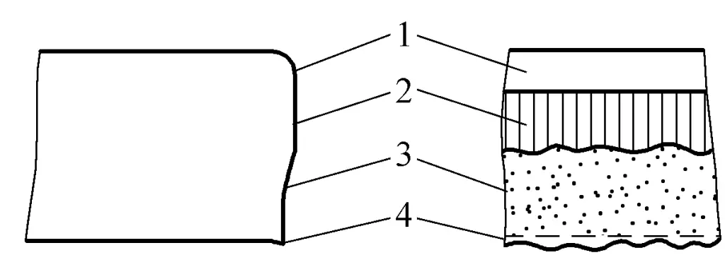
1 – Collapsed angle
2 – Bright band
3 – Shear zone
4 – Burr
The distribution ratio of the collapsed angle, bright band, shear zone, and burr on the entire shear surface varies with the material properties, thickness, blade shape, blade gap, and the method of pressing during shearing.
The blade edge is sharp, making it easy to squeeze and cut into the material, which is beneficial for increasing the bright band, while a larger front angle r o of the blade can increase the sharpness of the edge.
When the blade gap is large, the tensile stress in the material will increase, making it easy to produce shear cracks, and the plastic deformation stage ends earlier, thus the bright band will be smaller, while the shear zone, collapsed angle, and burr are all larger. Conversely, when the blade gap is small, the tensile stress in the material decreases, the production of cracks is suppressed, so the bright band becomes larger, while the collapsed angle, shear band, etc., all decrease.
However, both too large or too small a gap will cause the cracks on the upper and lower surfaces not to coincide on one line. When the gap is too small, latent cracks and larger burrs appear on the shear surface; when the gap is too large, the shear zone, collapsed angle, burr, and slope all increase, making the surface extremely rough.
If the material is pressed tightly on the lower blade, it can reduce the tensile stress, thereby increasing the bright band. Additionally, good plasticity and smaller thickness of the material can also increase the bright band.
From the analysis above, it can be concluded that the main measures to increase the bright band, reduce the collapsed angle and burr, and thereby improve the quality of the shear surface are: increasing the sharpness of the blade edge, taking the minimum value of a reasonable blade gap, and pressing the material tightly on the lower blade, etc.
The blade gap s is a geometric parameter to avoid collision between the upper and lower blades, reduce shearing force, and improve the quality of the shear surface. The reasonable gap value is a size range, with the upper limit called the maximum gap and the lower limit called the minimum gap. The determination of a reasonable blade gap mainly depends on the properties and thickness of the material being cut, as shown in Table 3-1. Various shearing equipment comes with very specific gap adjustment data plates, which can be used as a basis for adjusting the blade gap.
Table 3-1 Range of reasonable blade gap
| Material | Gap (as a percentage of plate thickness) | Material | Gap (as a percentage of plate thickness) |
| Pure Iron | 6~9 | Stainless Steel | 7~ 11 |
| Mild Steel (Low Carbon Steel) | 6~9 | Copper (Hard, Soft) | 6~ 10 |
| Hard Steel (Medium Carbon Steel) | 8 ~12 | Aluminum (Hard) | 6 ~10 |
| Silicon Steel | 7 ~ 11 | Aluminum (Soft) | 5~8 |
2. Shearing Equipment
There are many types of shearing machines commonly used in cold work, including: gantry type oblique shearing machine, transverse entry oblique shearing machine, disc shearing machine, vibrating shearing machine, and combined punching and shearing machine.
(1) Gantry Type Oblique Shearing Machine
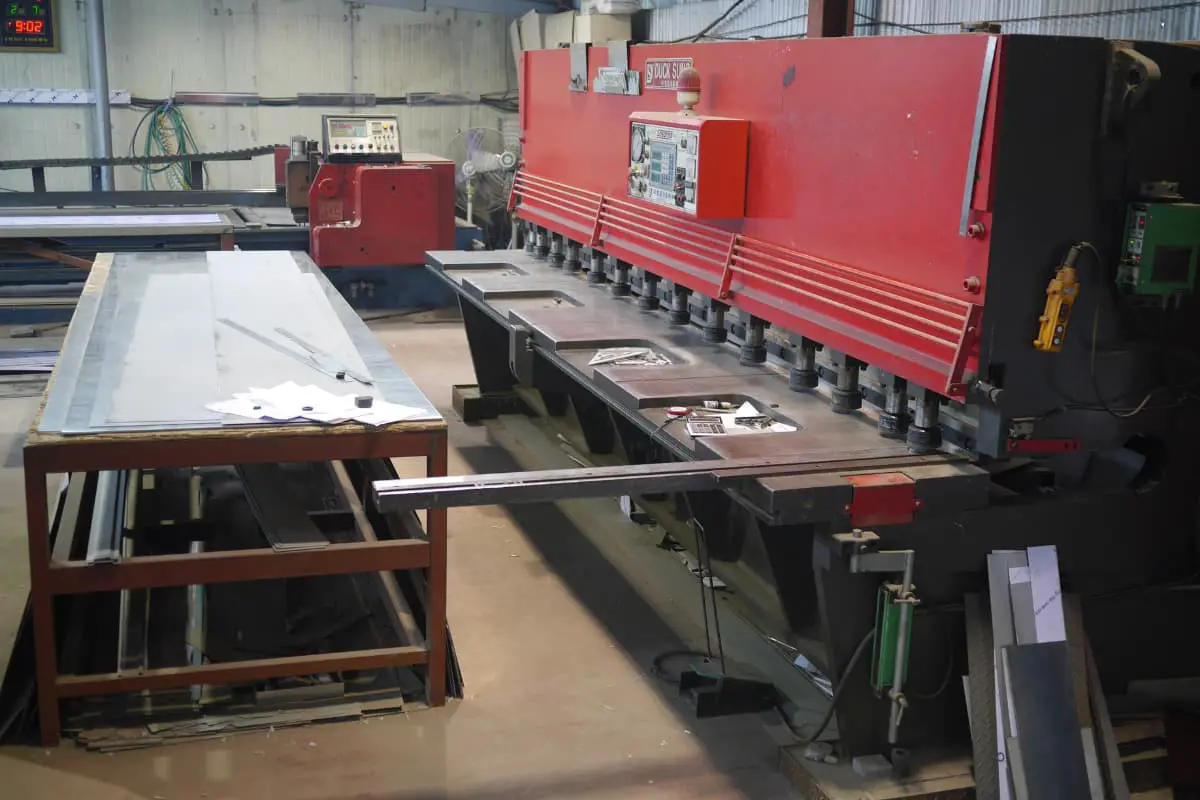
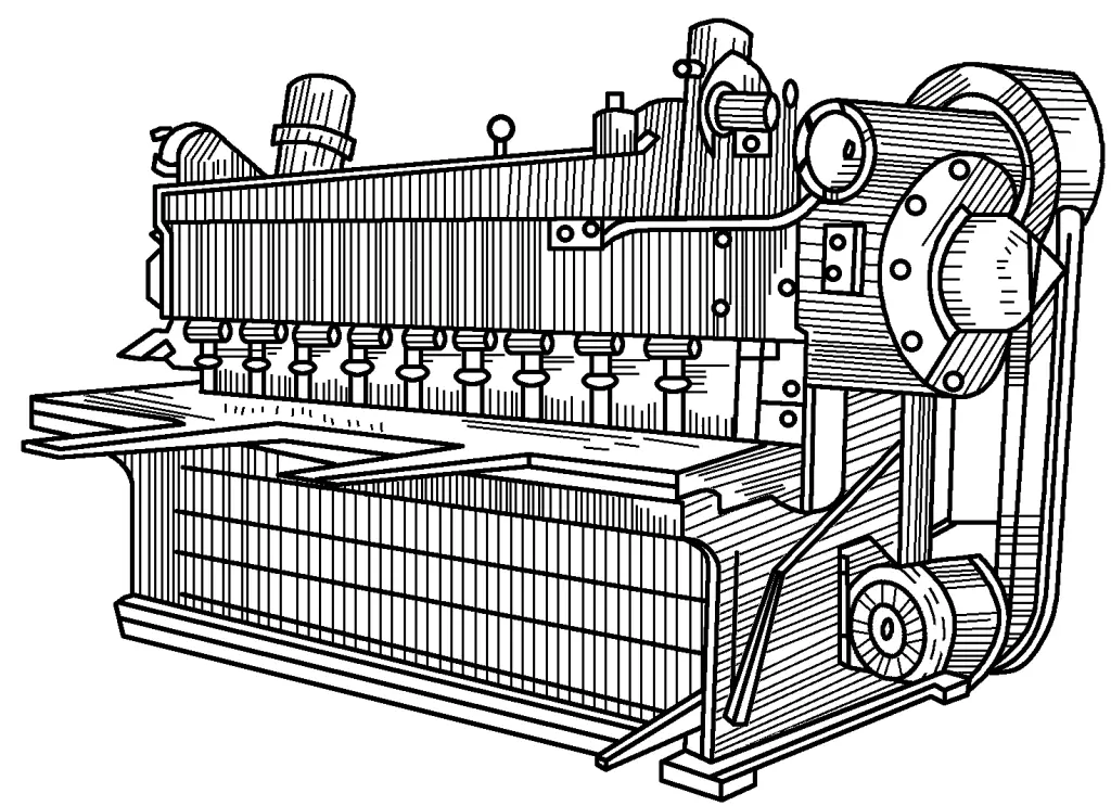
The gantry type oblique shearing machine, as shown in Figure 3-45, is mainly used for shearing straight cuts. It is simple to operate, convenient for feeding, fast in shearing speed, minimal deformation of the sheared material, and high precision of the cut surface, thus it is most widely used in sheet metal shearing.
(2) Transverse Entry Oblique Shearing Machine
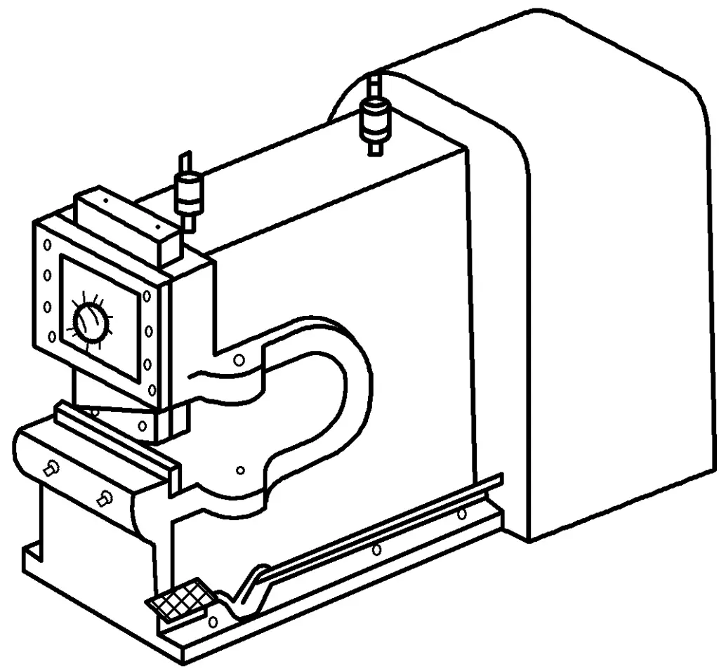
The transverse entry oblique shearing machine, as shown in Figure 3-46, is mainly used for shearing straight lines. During shearing, the material to be sheared can enter from the side of the shear and can move along the direction of shearing, allowing the shearing to be carried out in segments, with no limit on the shearing length. Compared to the gantry type oblique shearing machine, it has a larger shear blade angle φ, thus greater deformation during shearing, and it is more cumbersome to operate. Generally, it is better used for shearing thin and wide plates.
(3) Disc Shear Bed
The shearing part of the disc shear bed consists of upper and lower rotary cutters. During shearing, the upper and lower rotary cutters rotate in opposite directions at the same speed, and the material is sheared and conveyed between the two rotary cutters, as shown in Figure 3-47a. Cold work commonly uses the inclined rotary cutter disc shear bed, as shown in Figure 3-47b.
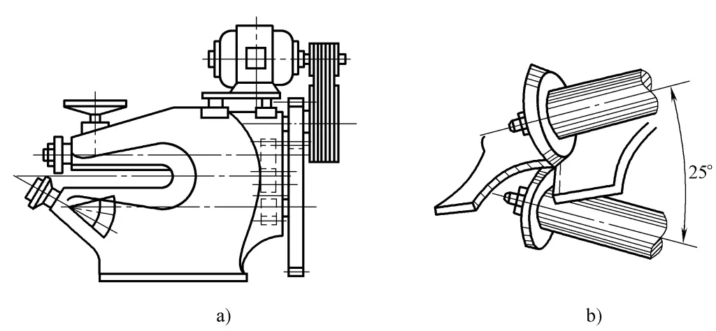
The disc shear bed, due to very little overlap of the upper and lower cutting edges and extremely short instantaneous shearing length, and the plate material rotation is basically unrestricted, is suitable for shearing curves and can continuously shear. However, the material being sheared bends significantly, and the edges have burrs, generally, the disc shear bed can only shear thinner plates.
(4) Vibrating Shear Bed
The vibrating shear bed, as shown in Figure 3-48, has both its upper and lower blades inclined with a large intersecting angle, and the shearing part is extremely short. During operation, the upper blade plate vibrates thousands of times per minute.
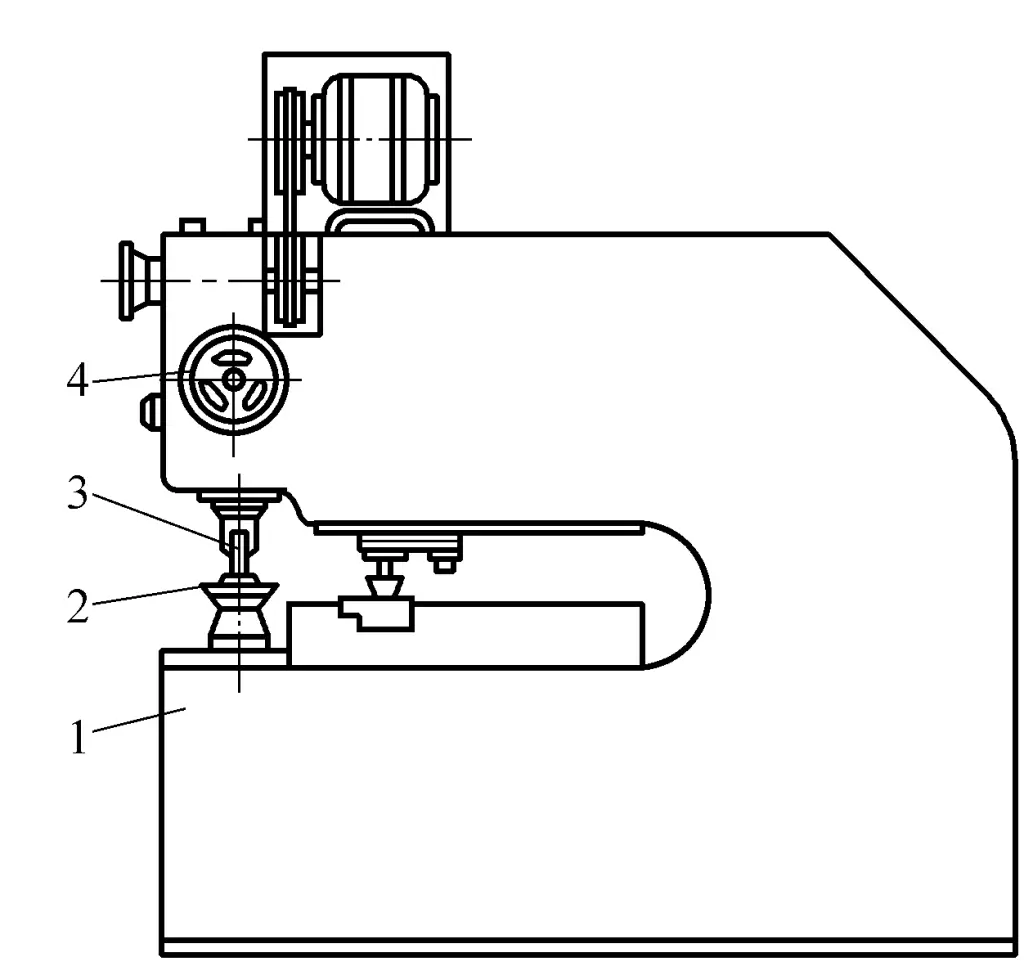
1—Bed Body
2—Lower Blade
3—Upper Blade
4—Stage Handle
Vibrating shear beds can cut various curves and inner holes on sheet metal, but their blades are prone to wear, the cut surfaces have burrs, productivity is low, and they can only cut thinner sheet metal.
(5) Combined punching and shearing machine
Combined punching and shearing machines usually consist of a slant shear, a profile steel shear, and a small punch, capable of cutting steel plates and various profile steels, and can perform small part stamping and punching.
3. Types and technical performance of shearing machinery
Operators of shearing machinery should have the ability to perform simple analysis of the shearing machinery used, which helps in mastering and improving shearing methods, and correctly maintaining and using the shearing machinery. Based on its structural form, one can preliminarily judge the type of shearing machinery, and then understand in detail the meaning represented by its model.
The model of the shear bed describes the type, characteristics, and basic operating parameters of the shear bed. For example, the Q11—13×2500 type gantry shearing machine, the meaning represented by its model
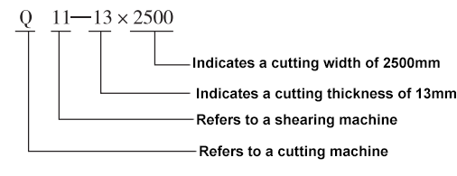
The national standard for machine tool numbers has been changed several times, therefore, for different shear bed models represented by the meanings, one should refer to the national standards related to the manufacturing era of the shear bed.
Various types of shearing equipment usually have their technical performance parameters made into nameplates embedded on the machine body, serving as the basis for shearing processing. The equipment’s technical performance is also detailed in the equipment manual. Therefore, by referring to the shear bed nameplate or manual, one can understand its technical performance.
4. Technological equipment of shearing machinery
To meet the needs of the shearing process, shearing machines usually have some simple process equipment set up. Figure 3-49 shows the process equipment of a typical gantry-type oblique shearing machine.
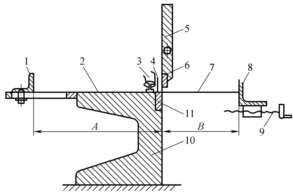
1 – Front stop
2 – Bed
3 – Press plate
4 – Grate
5 – Shear bed slider
6 – Upper blade
7 – Plate material
8 – Rear stop
9 – Screw
10 – Bed
11 – Lower blade
The hold-down plate prevents the turnover and movement of the plate during shearing to ensure shearing quality. The hold-down plate is driven by the working crankshaft, clamping the plate before the upper blade contacts the plate, completing automatic clamping. It can also achieve clamping purposes using manual eccentric wheels, becoming a manual clamping type. The gate is a safety device used to prevent hands or other objects from entering the shear mouth and causing accidents.
The front and rear gauge plates play a positioning role during shearing. When shearing a large number of parts with the same size, using the gauge plates for positioning can improve production efficiency and ensure product quality. Positioning gauge plates can also be installed on the bed.
Some factories have modified their shearing machines according to their specific conditions to improve automation, such as automatic loading and unloading, automatic feeding, positioning (for the shearing line), and clamping.
5. The impact of shearing processing on steel quality
Shearing is an efficient method of cutting metal, producing relatively clean and smooth cuts, but it also has certain disadvantages. Shearing steel can cause changes in mechanical properties and external shape, affecting the performance of the steel. This is mainly manifested in the following two aspects:
1) Narrow and long strip materials will exhibit significant bending and twisting deformation after shearing, and must be straightened afterwards. Additionally, if the blade gap is inappropriate, the sheared section will be rough and have burrs.
2) During the shearing process, due to the shearing force acting on the metal near the cut, squeezing and bending deformation occurs, causing an increase in metal hardness and yield point, a decrease in plasticity, and making the material brittle. This phenomenon is called cold work hardening. The width of the hardened area is related to the following factors:
1) Mechanical properties of steel. The better the plasticity of the steel, the larger the deformation area and the wider the hardening area; conversely, the higher the hardness of the material, the narrower the hardening area.
2) Thickness of the steel plate. The thicker the steel plate, the greater the deformation, and the wider the hardening area; conversely, the smaller it is.
3) Shear blade gap s. The larger the gap, the more severe the bending of the material, thus the wider the hardening area.
4) Shear blade angle φ. The larger the shear blade angle φ, when shearing the same thickness of steel plate, if the shearing force is smaller, then the hardening area is also smaller.
5) Sharpness of the shear blade. The blunter the shear blade, the greater the shearing force, and the wider the hardening area increases.
6) Position and clamping force of the clamping device. When the clamping device is closer to the shear blade and the clamping force is greater, the material is less likely to deform, and the width of the hardening area is reduced.
In summary, the width of the cold work hardening area caused by shearing processing of steel is related to various factors and is the result of a comprehensive effect. When the thickness of the sheared steel plate is less than 25mm, the width of the hardening area is generally within the range of 1.5~2.5mm.
For the cold work hardening phenomenon on the edge of the plate, when manufacturing important structures or when cold stamping processing is still required after shearing, it is necessary to undergo milling, planing, or heat treatment to eliminate the hardening phenomenon.
II. Principles and equipment of punching
1. Principles of punching
The processing method of using a die on a press to separate one part of the sheet from another is called blanking. Blanking is also a method of cutting steel, and for batch production of parts or shaped products, using blanking can improve production efficiency and product quality.
During blanking, the material is placed between the punch and die, and under the action of external forces, the punch and die generate a pair of shearing forces (the shearing line is usually closed), and the material is separated under the action of shearing forces, as shown in Figure 3-50.
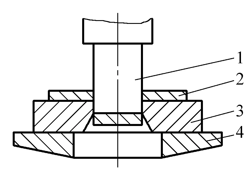
1—Punch
2—Sheet material
3—Die
4—Punch press worktable
The basic principle of blanking is the same as shearing, except that the straight cutting edge used in shearing is changed to a closed circular or other form of cutting edge.
The deformation of the material and the state of the cross-section during the blanking process are roughly the same as during shearing.
The process from the punch contacting the sheet material to the separation of the sheet material is completed instantaneously. When the gap between the punch and die is normal, the blanking deformation process can generally be divided into the following three stages:
The first stage is the elastic deformation stage. As shown in Figure 3-51a, when the punch starts to contact the sheet and presses down, under the pressure of the punch and die, the sheet begins to undergo complex deformations such as elastic compression, bending, and stretching (AB’>AB). At this time, the punch slightly presses into the sheet, and the lower part of the sheet also slightly presses into the die hole, forming a very small fillet at the contact point with the punch and die edges.

a) Elastic deformation stage
b) Plastic deformation stage
c), d) Fracture separation stage
Meanwhile, the sheet slightly arches, the harder the material, the larger the gap between the punch and die, and the more severe the arching. As the punch presses down, the stress on the sheet near the cutting edge gradually increases until it reaches the elastic limit, ending the elastic deformation stage.
The second stage is the plastic deformation stage. As the punch continues to press down, causing the stress in the deformed area of the sheet to exceed its yield point and reach plastic conditions, it enters the plastic deformation stage, as shown in Figure 3-51b.
At this time, the depth of the punch pressing into the sheet and the sheet pressing into the die gradually increases, producing plastic shearing deformation, forming a bright sheared surface. As the punch descends, the degree of plastic deformation increases, the material in the deformed area hardens, the resistance to deformation continuously rises, and the punching force also increases accordingly, until the stress near the cutting edge reaches the tensile strength, ending the plastic deformation stage.
Due to the gap between the punch and die, this stage also involves bending and stretching deformations, and the larger the gap, the greater the bending and stretching deformations.
The third stage is the fracture separation stage. When the stress inside the sheet reaches the tensile strength, and the punch presses down further, microcracks subsequently occur at the parts of the sheet in contact with the punch and die edges, as shown in Figure 3-51c. The starting point of the cracks is generally on the side close to the cutting edge, and usually first occurs on the side near the die edge, and then on the side near the punch edge.
As the punch continues to press down, the already formed upper and lower micro-cracks will continue to expand towards the interior of the plate along the direction of maximum shear stress. When the upper and lower cracks coincide, the plate is sheared and separated, as shown in Figure 3-51d. Subsequently, the punch pushes the separated material into the die hole, and the punching deformation process ends.
In the three stages of the punching deformation process, the external force and time required for each stage are not the same. Generally speaking, the punching time often depends on the material properties, and the duration is shorter when the material is more brittle.
2. Punching equipment
(1) Structure of the press
Punching is generally carried out on a press. Commonly used presses include crank presses and eccentric presses, both of which operate on the same principle, with the main difference being the main spindle used.
The basic structure of a crank press is shown in Figure 3-52a, and the working principle is shown in Figure 3-52b. The body of the press and the worktable are integrated, with vertical guide rails on the body above the worktable surface, allowing the slider to move up and down. The upper and lower punching dies are mounted on the slider and the worktable surface respectively.
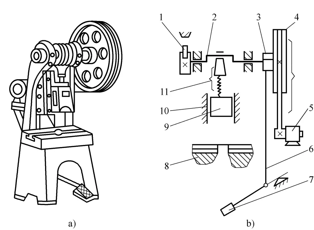
a) Appearance
b) Working principle diagram
1 – Brake
2-Crankshaft
3-Clutch
4-Large pulley
5-Electric motor
6-Push rod
7-Pedal
8-Workbench
9-Slider
10-Guide rail
11-Connecting rod
When the punch press is working, the motor first drives the large pulley to idle through the transmission belt. After stepping on the pedal, the clutch closes and drives the crankshaft to rotate, which then drives the slider to move up and down along the guide rail through the connecting rod, performing punching.
If the pedal is immediately released after being stepped on, the slider stops at the highest position after one punching stroke under the action of the brake; if the pedal is continuously pressed, the slider keeps moving up and down to perform continuous punching.
(2) Technical performance parameters of the punch press
The technical performance parameters of the punch press have a significant impact on the punching work. When processing punching, it is necessary to select the punch press according to the technical performance parameters.
1) Tonnage and rated power of the punch press.
The tonnage and rated power of the punch press are two indicators that mark the working capacity of the punch press. The required punching force and power for actual punched parts must be less than these two indicators of the punch press. When punching thin plates, the required punching power is relatively small and generally can be disregarded.
2) Closed height of the punch press.
The distance from the lower surface of the slider at its lowest position to the worktable surface. When the adjustment device adjusts the slider to the upper limit position, the closed height reaches its maximum value, which is called the maximum closed height. The closed height of the punch press should be compatible with the closed height of the mold.
3) Stroke of the slider.
The distance the slider travels from the highest position to the lowest position, also known as the stroke. The size of the slider stroke determines the closed height and open height of the punch press used, and it should ensure smooth feeding and retracting during the punching process.
4) Punch press table size.
When punching, the size of the die should be adapted to the size of the punch press worktable to ensure that the die can be firmly installed on the table.
Other technical performance parameters have little impact on the punching process and can be appropriately selected according to specific circumstances.
(3) Precautions for using the punch press
1) Before use, inspect all parts of the punch press and fill all lubrication points with lubricating oil.
2) Check whether the clearance between the bearing shells and the tightness of the brake are appropriate.
3) Check whether there are foreign objects trapped in the moving parts.
4) Frequently check the wear and clearance of the punch press’s slider and guide rail. Excessive clearance will affect the guiding accuracy, therefore, the clearance between the guide rails must be adjusted regularly. If the wear is too severe, maintenance must be carried out.
5) When installing the die, align the pressure center of the die with the pressure center of the punch press, and ensure that the clearance between the male and female dies is even.
6) After turning on the switch, run the machine empty 3 to 5 times to check whether the control device and operating state are normal.
7) When punching, concentrate, do not step on the pedal arbitrarily, and it is strictly forbidden to stretch hands between molds or have the head contact the slider to avoid accidents.
8) Do not punch materials that are too hard or have been quenched. The punch press must not be overloaded.
9) For long-time punching, pay attention to check whether the mold is loose and whether the gap is uniform.
10) After stopping punching, cut off the power supply or lock the safety switch. The punched parts and scrap materials should be removed in time to keep the area around the punch press free of obstacles.
III. Principles and Methods of Grinding Wheel Cutting
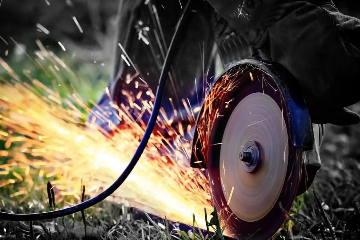
Grinding wheel cutting uses the high-speed rotation of the grinding wheel to generate heat through friction with the workpiece, melting to form a cut. Grinding wheel cutting is straightforward, efficient, easy to operate, and widely used in cutting angle steel, channel steel, flat steel, steel pipes, and other profiles, especially suitable for cutting stainless steel, bearing steel, and various alloy steels.
Figure 3-53 shows a widely used portable grinding wheel cutting machine, which consists of a cutting power head 4, a rotatable clamp 1, a central adjustment mechanism 3, and a base 2.
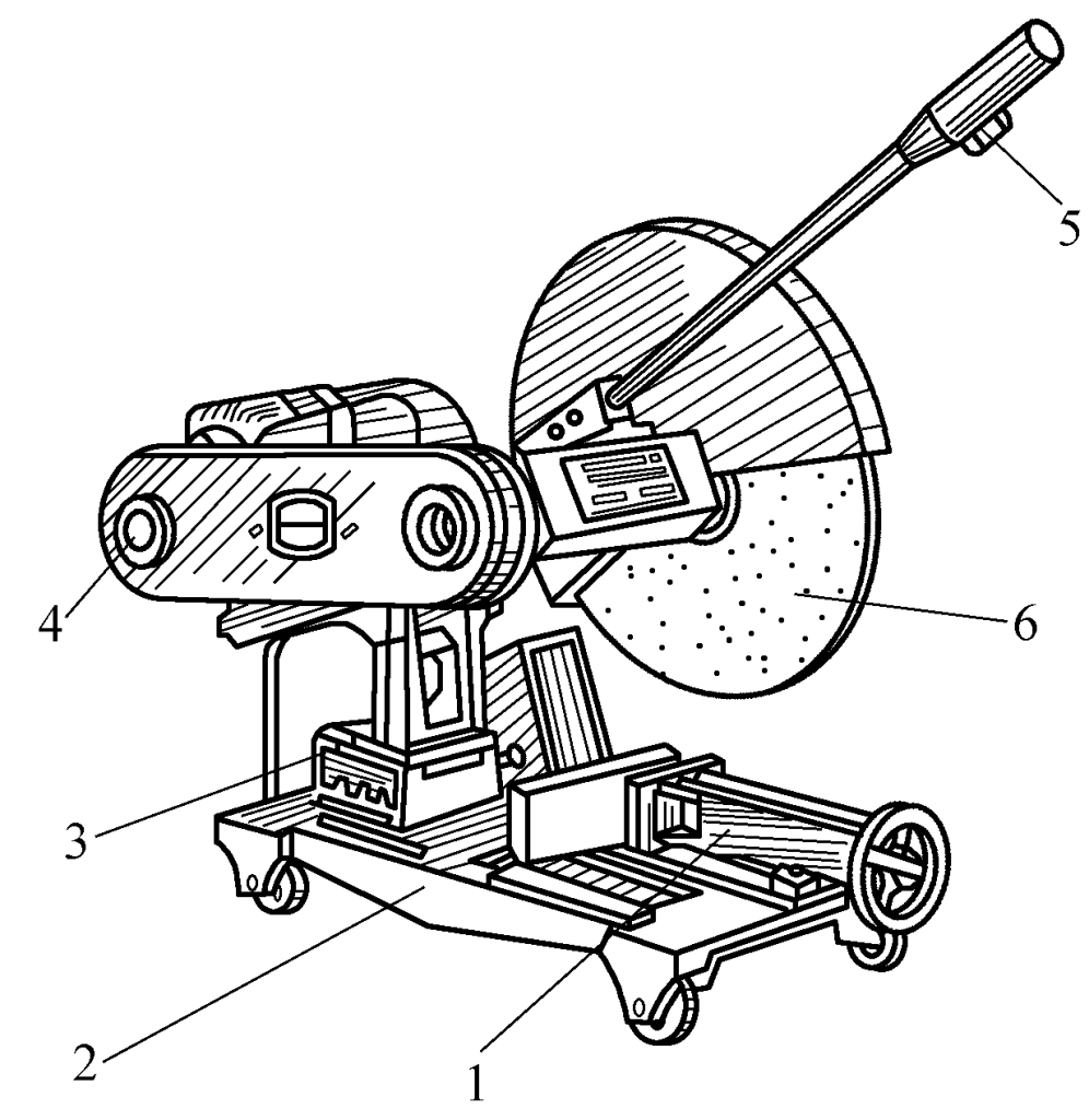
1—Rotatable Clamp
2—Base
3—Central Adjustment Mechanism
4—Cutting Power Head
5—Switch
6—Grinding Wheel
The commonly used grinding wheel has a diameter of 300~400mm, thickness of 3mm, and a wheel speed of 2900r/min, with a cutting line speed of 60m/s. To prevent the grinding wheel from bursting, a fiber-reinforced grinding wheel is used. The entire power head and grinding wheel center can be adjusted and rotated according to cutting needs, which can be achieved through a handle that also has a switch to control the operation of the motor.
The rotatable vise can adjust its angle with the grinding wheel spindle (0°~45°) as needed. To adjust, simply loosen the hex screw, pull out the positioning pin, and the jaws can rotate to the required angle around the pivot screw. There are four rollers installed under the base, allowing the entire grinding wheel cutter to be movable.
During cutting, the profile is mounted on the rotatable vise and clamped, turn on the switch on the handle to drive the motor, which through belt transmission, spins the grinding wheel at high speed. Once the wheel speed stabilizes, operate the handle to cut.

