Calculate the Minimum Bending Edge for Sheet Metal
When it comes to precision in sheet metal fabrication, understanding the intricacies of bending is crucial. Ever wondered how to…
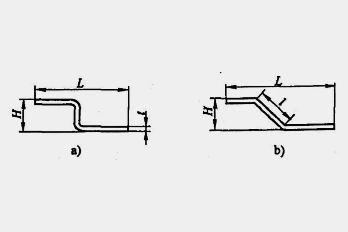
Z-bending, also known as offset bending, can be categorized into straight edge offset bending and slanted edge offset bending depending on the forming angle (see Figure 1). The processing method is determined based on the offset height.
In the case of straight edge offset bending (Figure 1), when the offset height H falls within the range 0<H≤2t, and the batch is not large, it can be processed using an offset die on a bending machine, as shown in Figure 2.
When the offset height is within 2t<H≤ the minimum bend height of the Z-bend (offset), consideration should be given to using an offset die, a simple die, or a Z-bending die with a discharge device, depending on the actual situation. When H> the minimum bend height of the Z-bend (offset), the bending machine is used for bidirectional bending processing.
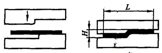
The first step of processing Z-bending (offset) on a bending machine is calculated the same as the previously uploaded article on V-bending. The initial state when bending into a Z shape in the second step is shown in Figure 3.
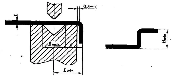
As can be seen from the figure, the processes of Z-bending and V-bending are very similar, and there is also the issue of the minimum bend height of Z-bending. Due to the limitation of the lower die structure, the minimum dimension Lmin from the bending line (symmetry line of the lower die groove) to the upper edge of the Z shape for 90° Z-bending is larger than that of V-bending, which can be calculated as follows:
Lmin = Bvmin/2 + 6 + t + (0.5~1)
Where:
b – Structural dimensions from the lower die groove to the edge (in mm), usually b > 5mm.
The formula for calculating the minimum edge height of Z-bending (offset) is:
Hmin = (Bvmin-x)/2 + b + 2t + (0.5~1)
The recommended values for the minimum edge height of Z-bending (offset) for different material thicknesses t are shown in Table 1.
Table 1: Recommended Values for the Minimum Bend Height of Z-bending (Offset) (Unit: mm)
| Serial Number | Material Thickness t | Die Slot Width Bv | Punch Arc Radius r0 | Z-Shaped Bend Height Hmin |
| 1 | 0.5 | 4· | 0.2 | 8.5 |
| 2 | 0.6 | 4 | 0.2 | 8.8 |
| 3 | 0.8 | 5 | 0.8 or 0.3 | 9.5 |
| 4 | 1.0 | 6 | 1 or 0.5 | 10.4 |
| 5 | 1.2 | 8(or 6) | 1 or 0.5 | 11.7(or 10.7) |
| 6 | 1.5 | 10(or 8) | 1 or 0.5 | 13.3(or 12.3) |
| 7 | 2.0 | 12 | 1.5 or 0.5 | 15.2 |
| 8 | 2.5 | 16(or 14) | 1.5 or 0.5 | 18.2(or 17.2) |
| 9 | 3.0 | 18 | 2 or 0.5 | 20.1 |
| 10 | 3.5 | 20 | 2 | 22 |
| 11 | 4.0 | 25 | 3 | 25.5 |
Note: The data in the table are empirical and are provided for reference only.