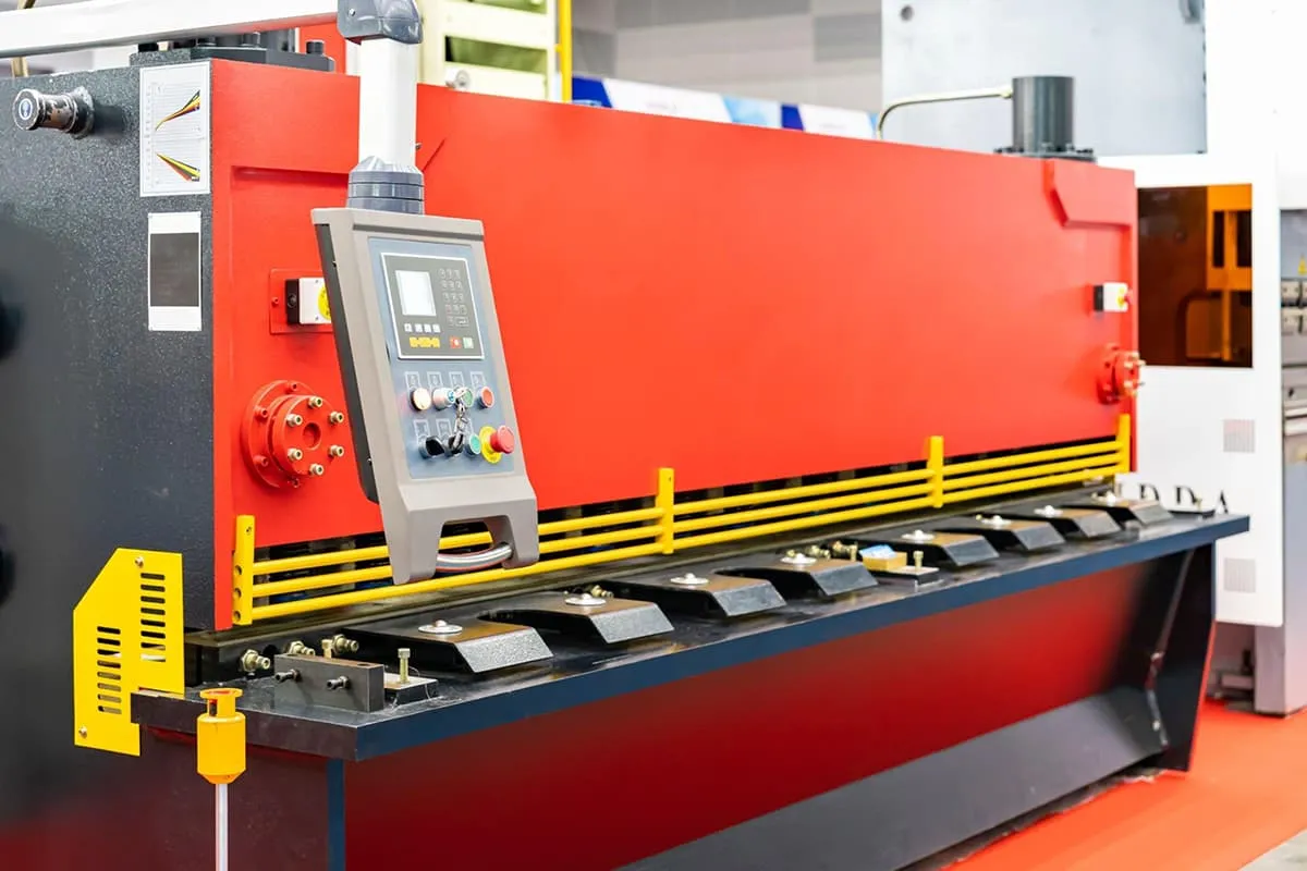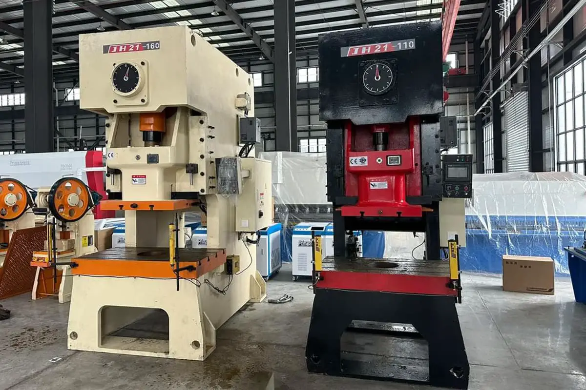
Blanking with a press machine must be done through a shearing die. In the shearing process, essentially, there is no fundamental difference between shearing die blanking and shear bed blanking. The blade design of the shearing die and the shear bed are basically the same.
I. Structural characteristics and classification of the shearing die
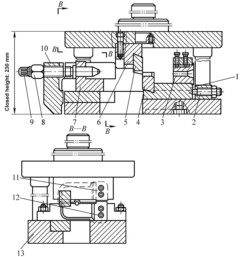
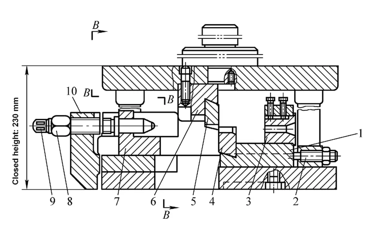
- 1—Base plate
- 2—Stop pin
- 3—Guide bushing
- 4,5—Lower, Upper blade
- 6—Upper tool holder
- 7—Slider
- 8—Nut
- 9—Screw
- 10—Bracket
- 11,12—Upper, Lower pressure plate
- 13—Lower tool holder
1. Structural characteristics of the shearing die (see Table 1)
Table 1 Structural characteristics of the shearing die
| Basic components | Characteristics |
| 1) Upper mold plate for clamping the moving blade and lower mold plate for clamping the fixed blade 2) Guide device of the upper mold plate 3) Positioning block device for controlling the length of the cut blank 4) Clamping device to prevent the rod from flipping when being cut | 1) The cutting accuracy should be higher than that of the shearing bed, and the cutting diameter is generally below Φ40mm 2) When selecting equipment based on shearing force, not only the nominal tonnage of the press should be considered, but also the load curve of the press used |
2. Classification of shearing dies (see Table 2)
Table 2 Classification of shearing dies
| Classification method | Type | Die structure |
| According to the groove structure | General Shearing | 1) Open shearing die (see Figure 1) 2) Semi-closed shearing die (see Figure 2) 3) Closed shearing die (see Figure 3) |
| Precision Shearing | 1) High-speed hammer shearing die (see Figure 4) 2) Radial clamping shearing die (see Figure 5) 3) Differential shearing die (see Figure 6) 4) Axial pressure shearing die (see Figure 7) 5) Iso-mass shearing (see Table 5) | |
| By type slot quantity | 1) Single type slot shear die (see Figure 8) 2) Double type slot shear die (see Figure 9) 3) Multiple type slot shear die (see Figure 10) | |
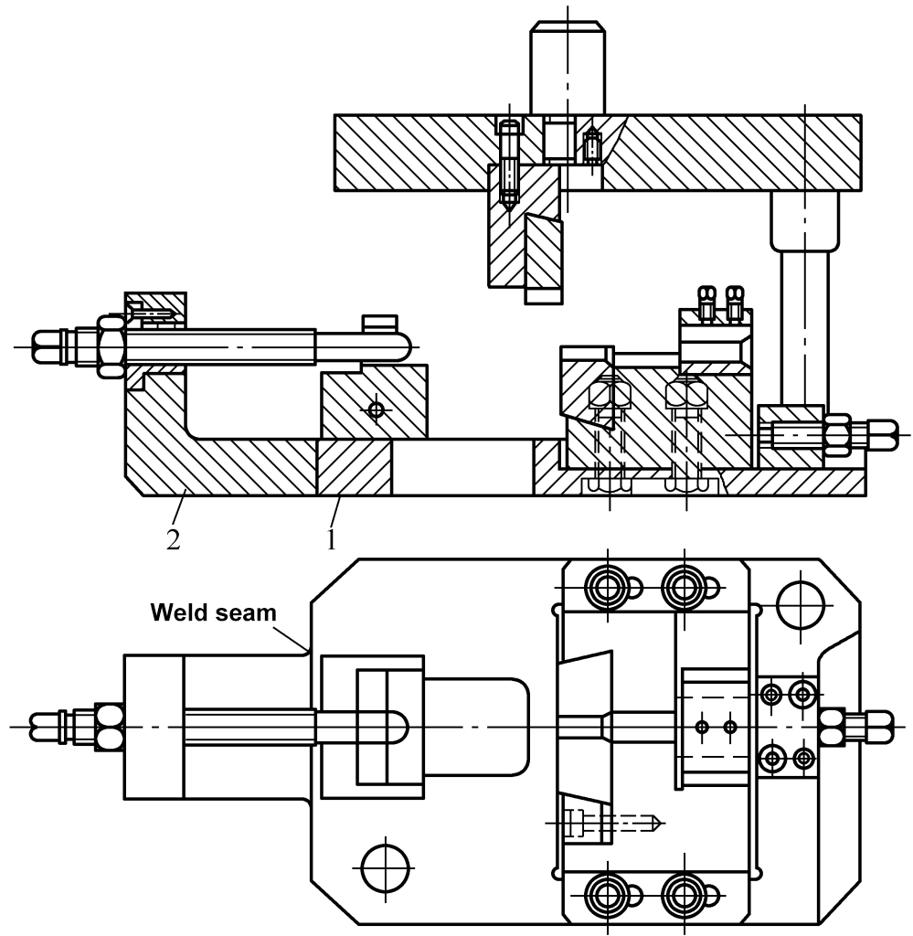
1—Base plate 2—Bracket
Note: 1. This diagram is of the shear die used on a 500kN press, its structure is basically the same as the attached diagram in Table 1, except that bracket 2 is welded on base plate 1.
2. When shearing hot-rolled bar material, the blade edge radius can be selected according to Table 3. Guide sleeve size D is selected according to Table 4.
Table 3 Blade edge radius dimensions (unit: mm)
| Bar diameter d | R |
| 8 | 4.3 |
| 9 | 4.8 |
| 10 | 5.4 |
| 11 | 5.9 |
| 12 | 6.4 |
| 13 | 6.9 |
| 14 | 7.4 |
| 15 | 7.9 |
| 16 | 8.4 |
| 17 | 8.9 |
| 18 | 9.4 |
Table 4 Guide Sleeve Diameter Dimensions (unit: mm)
| Bar Diameter d | D |
| 8 | 6.5 |
| 9 | 9.5 |
| 10 | 10.5 |
| 11 | 11.7 |
| 12 | 12.7 |
| 13 | 13.7 |
| 14 | 14.5 |
| 15 | 16 |
| 16 | 17 |
| 17 | 18 |
| 18 | 19 |
Table 5 Equal Mass Shearing
| Serial Number | Method | Description |
| 1 | Weighing Method | Use an electronic scale to weigh the first section of the billet mass, and automatically correct the stopper position based on the difference from the given billet mass. Due to the high accuracy of electronic scales in recent years, the accuracy of billet mass can be well controlled. However, the head of domestic materials is often irregular, which will affect the accuracy. The method of measuring the mass of the second section of the blank can be used to achieve the purpose of equal mass. |
| 2 | Method of Measuring the Cross-sectional Area of Bar Material | Before shearing, measure the cross-sectional area of the bar material and calculate the required billet length to automatically adjust the stopper position. Generally, a device for measuring the cross-sectional area of the bar material is set up at the other end of the roller conveyor where the material is fed, and the measurement is carried out before shearing. |
| 3 | Overall Weighing Method | Before shearing, weigh the entire bar with two electronic scales and measure the total length of the bar to calculate the required billet length, thereby adjusting the stop block position |
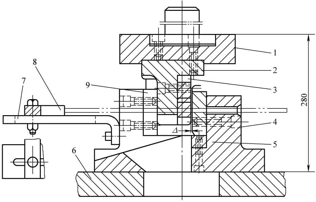
- 1—Upper Template
- 2—Upper Knife Holder
- 3—Upper Knife
- 4—Base
- 5—Support Plate
- 6—Workbench
- 7—Material Stop Bracket
- 8—Baffle
- 9—Guide block
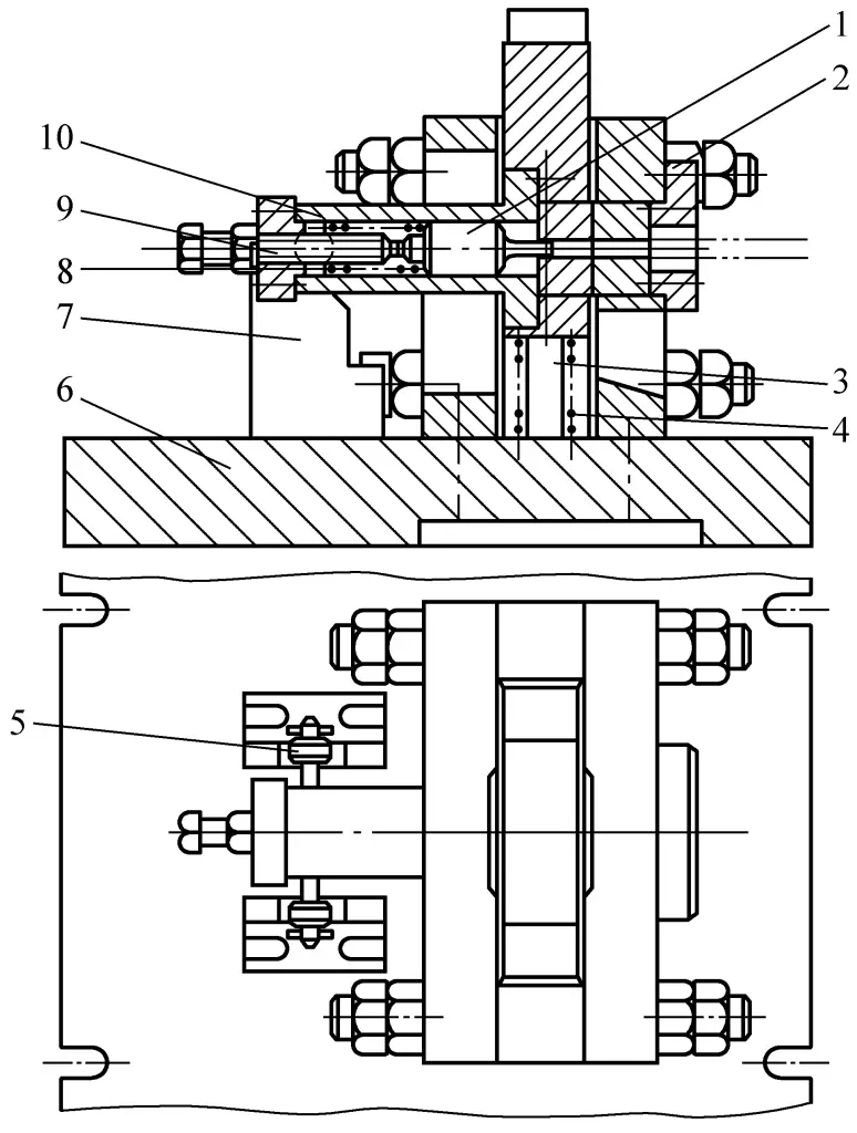
- 1—Positioning block
- 2—Spacer
- 3—Spring core rod
- 4—Return spring
- 5—Roller
- 6—Lower template
- 7—Inclined plate
- 8—Sleeve
- 9—Bolt
- 10—Spring
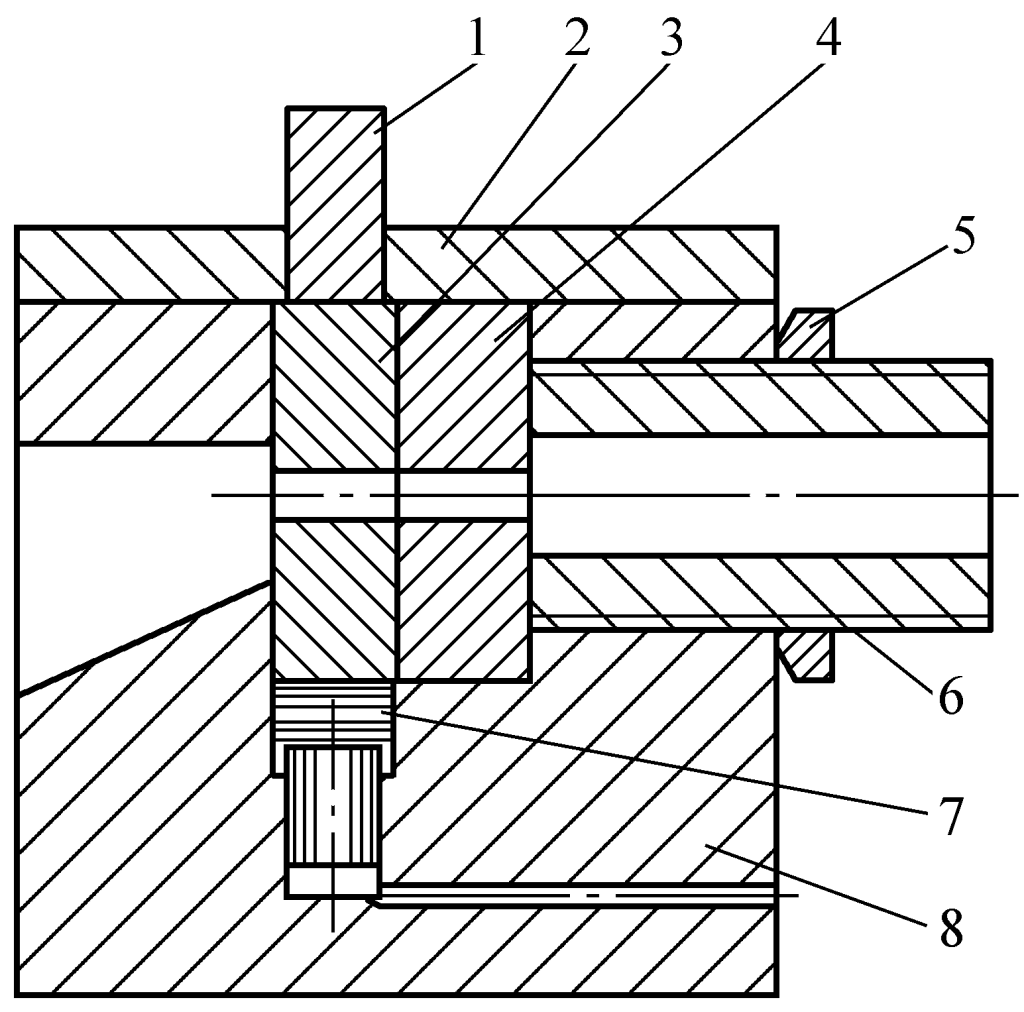
1—Punch
2—Cover plate
3—Moving blade
4—Fixed blade
5—Adjusting nut
6—Adjusting threaded tube
7—Buffer device
8—Die holder
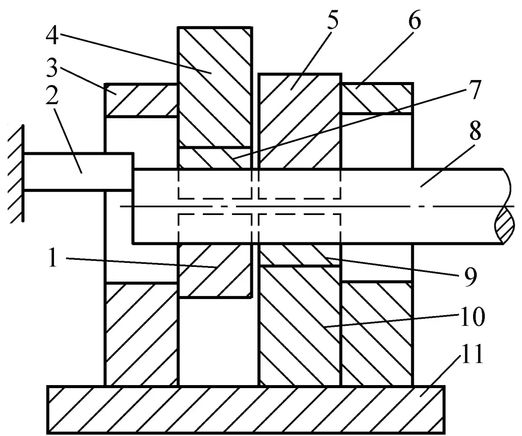
1—Moving blade pressure block
2—Positioning block
3—Front wall plate
4—Moving blade holder
5—Fixed blade pressure block
6—Rear wall plate
7—Moving blade
8—Bar stock
9—Fixed blade
10—Fixed blade holder
11—Base plate
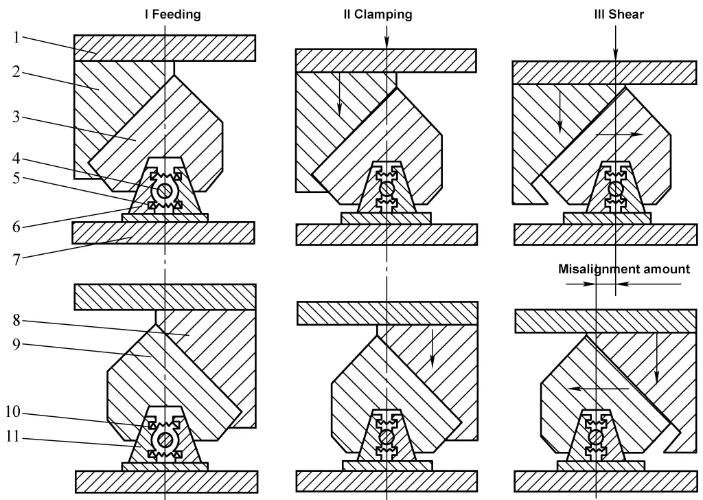
1—Top plate
2—Rear slant iron
3—Rear wedge
4—Bar stock
5, 10—Spring
6—Rear clamp (with embedded blade)
7—Base plate
8—Front inclined iron
9—Front wedge
11—Front clamp (with embedded blade)
Note: 1. The action process of the differential shearing die: The top plate 1 and the front and rear inclined irons 8, 2 are in the highest position, the front and rear clamps 11, 6 are in the open state under the action of springs 10, 5, at this time the rod material 4 is fed in; the press slide descends; pressure is applied to the top plate, through the front and rear inclined irons and front and rear wedges 9, 3 forcing the front and rear clamps to overcome the resistance of the springs, clamping the rod material; the slide descends further, the rear inclined iron forces the rear wedge to move the rear clamp to the right, while the front inclined iron forces the front wedge to move the front clamp to the left, when a certain amount of relative movement is reached, the rod material is sheared off.
2. The shearing quality of the differential shearing die is shown in Table 6.
Table 6 Shearing Quality of Differential Shearing Die
| Shearing Quality | General mold hot shearing | Differential Cold Shear |
| Verticality | ≈5° | <1° |
| Settlement Amount/mm | 2~3 | 0.5~0.6 |
| Length Error/mm | 1~2 | ±0.2 |
| Section Quality | Rough Unevenness | Flat and Smooth |
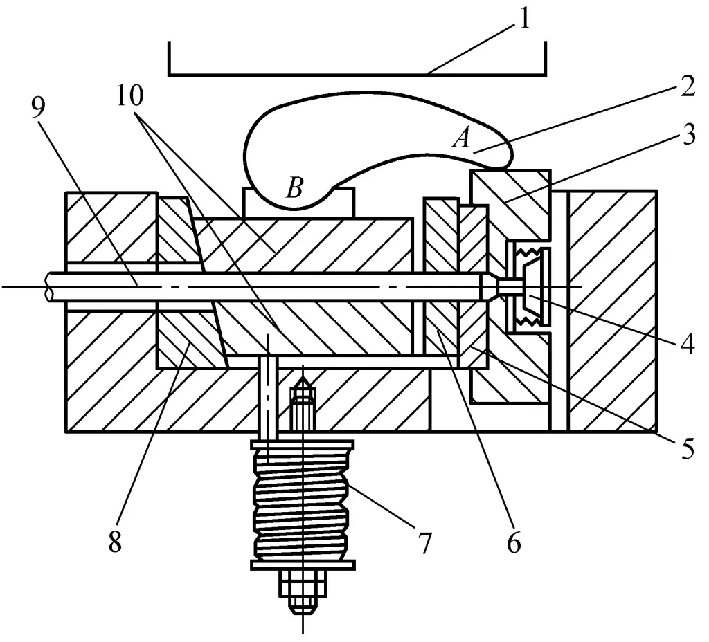
1—Press Slide
2—Control Lever
3—Active mold
4—End block ejector
5—Active shear blade
6—Fixed shear blade
7—Spring
8—Wedge
9—Bar stock
10—Divisible clamping mold
Note:
(1) The working process of axial pressure shearing: The bar stock 9 is placed in the divisible clamping mold 10, the press slide 1 moves downward pressing on the control lever 2, and causes it to rotate around point A (since the shear resistance of the bar stock exists, the active mold 3 does not move), thus applying clamping force to the divisible clamping mold, and with the help of the wedge 8, an axial force is applied to the bar stock, thereby generating axial compressive stress in the bar stock.
(2) After all gaps in the wedge disappear, the slide pushes the lever to rotate around point B, forcing the active shear blade to shear the bar stock. When the downward stroke of the active shear blade ends, it activates the ejector 4, ejecting the billet under the fixed shear blade 6. The horizontal component of the clamping force generated by the wedge also ensures that the fixed and active shear blades are tightly pressed together during shearing.
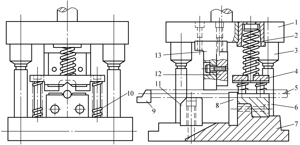
1—Upper template
2—Compression spring
3—Guide sleeve
4—Compression block
5—Rod material
6—Guide post
7—Lower template
8—Fixed knife
9—Positioning block
10—Compression block return spring
11—Back pressure block
12—Moving blade
13—Power gripper
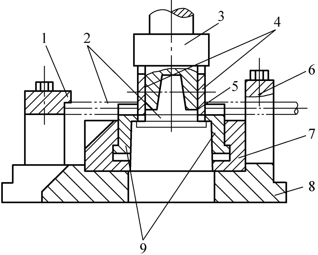
1—Support frame
2—Sheared blank
3—Upper die seat
4—Upper blade
5—Bar stock
6—Guide frame
7—Knife holder
8—Die holder
9—Lower knife
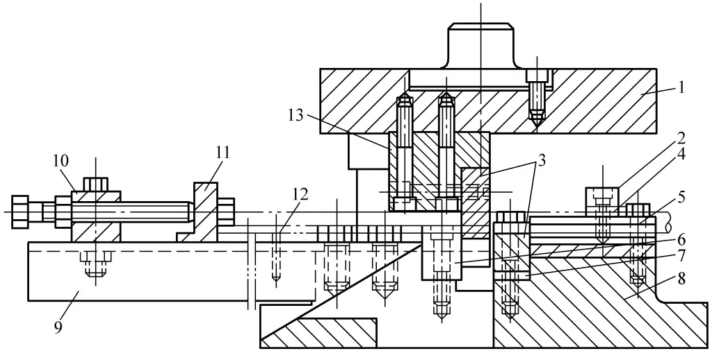
1—Upper template
2—Pressing plate
3—Upper and lower knives
4—Washer
5—Guide plate
6—Guide block
7—Support Pad
8—Base
9—Bracket
10—Support Plate
11—Stop Plate
12—Support Rod
13—Upper Tool Holder
II. Press Cutting Blade
1. Single Groove Blade Structure and Dimensions (see Table 7)
Table 7 Single Groove Blade Structure and Dimensions (unit: mm)
| Upper blade | Lower blade | |
| Simplified Diagram | 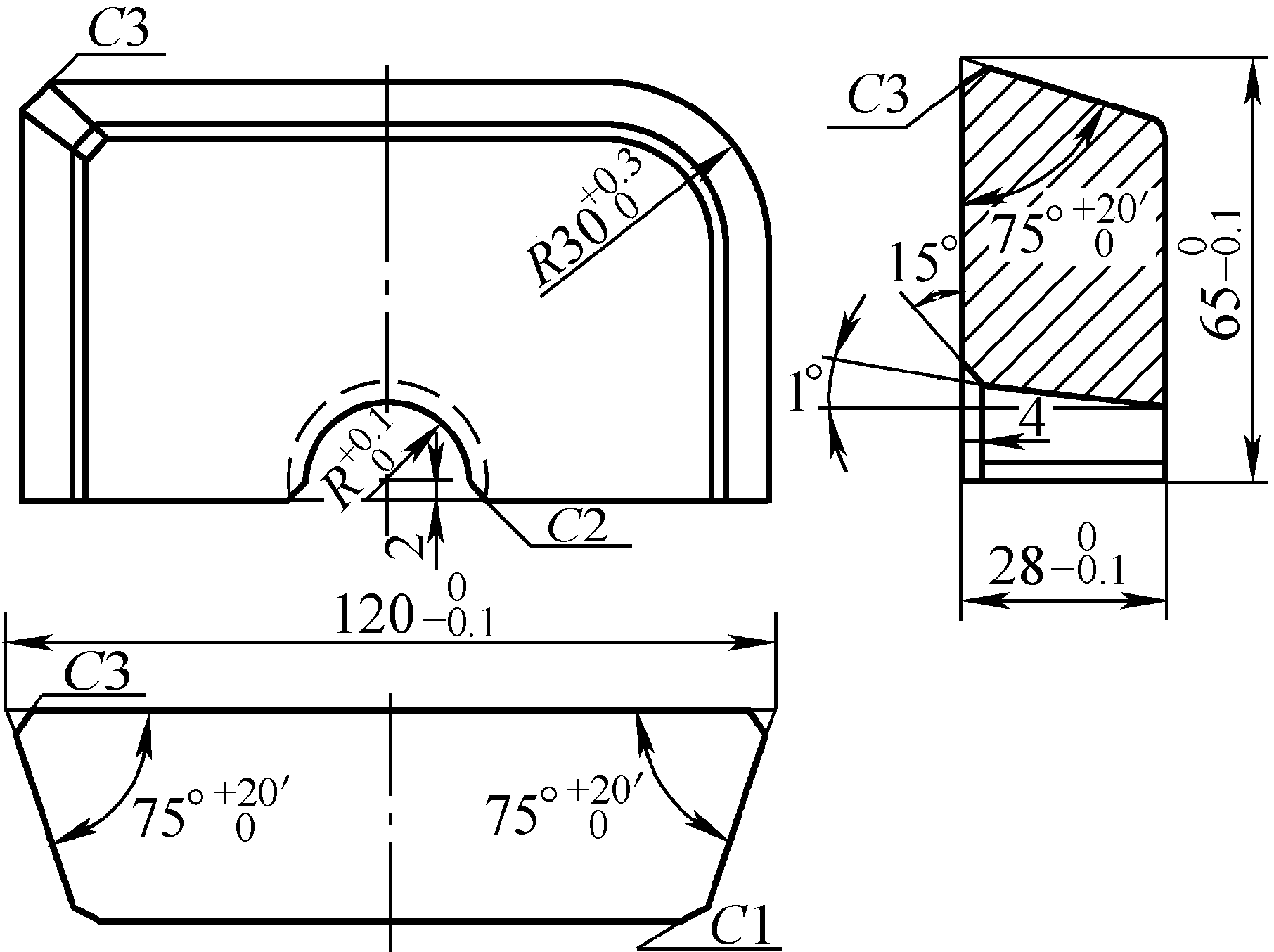 | 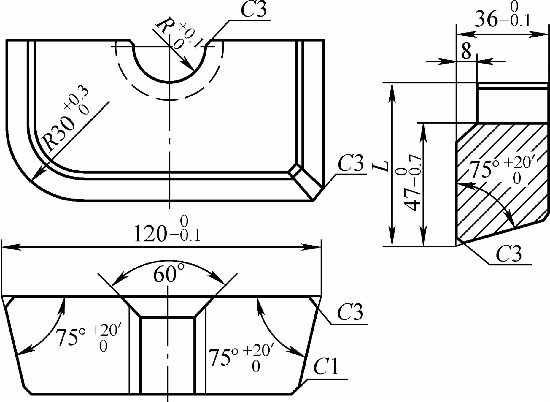 |
| Bar diameter d | R | |
| 11 | 5.85 | |
| 12 | 6.35 | |
| 13 | 6.85 | |
| 14 | 7.35 | |
| 15 | 8 | |
| 16 | 8.5 | |
| 17 | 9 | |
| 18 | 9.5 | |
| 19 | 10 | |
| 20 | 10.5 | |
| 21 | 11. 0 | |
| 22 | 11. 5 | |
| 23 | 12. 0 | |
| 24 | 12.5 | |
| 25 | 13 | |
| 26 | 13.5 | |
| 27 | 14 | |
| 28 | 14.5 | |
| 29 | 15 | |
| 30 | 15.5 | |
| 31 | 16 | |
| 32 | 16.5 | |
2. Double-groove blade structure and dimensions (see Table 8)
Table 8 Double-groove blade structure and dimensions (unit: mm)
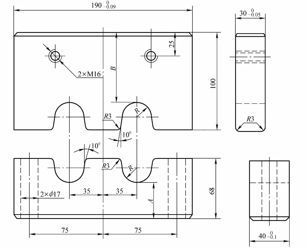
| Bar diameter d | 28 | 30 | 32 | 34 | 36 |
| R | 14.5 | 15.5 | 16.5 | 17.5 | 18.5 |
| A | 40 | 40 | 41 | 42 | 42 |
| B | 65 | 65 | 64 | 63 | 63 |
3. Multi-groove blade structure and dimensions (see Table 9)
Table 9 Multi-groove blade structure and dimensions (unit: mm)
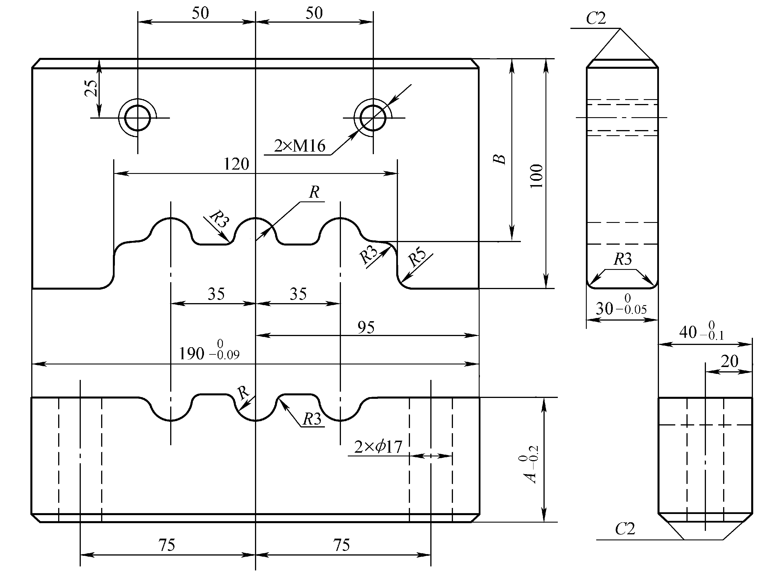
| Bar diameter d | 14 | 16 | 18 | 20 | 22 | 25 | 28 |
| R | 7.5 | 8.5 | 9.5 | 10.5 | 11.5 | 13 | 14.5 |
| A | 45 | 46 | 48 | 48.5 | 50 | 52 | 54.5 |
| B | 78 | 78 | 79 | 80.5 | 81 | 82 | 82.5 |
III. Guide bushing structure and dimensions
See Table 10 for guide sleeve structure and dimensions.
Table 10 Guide Sleeve Structure and Dimensions (Unit: mm)
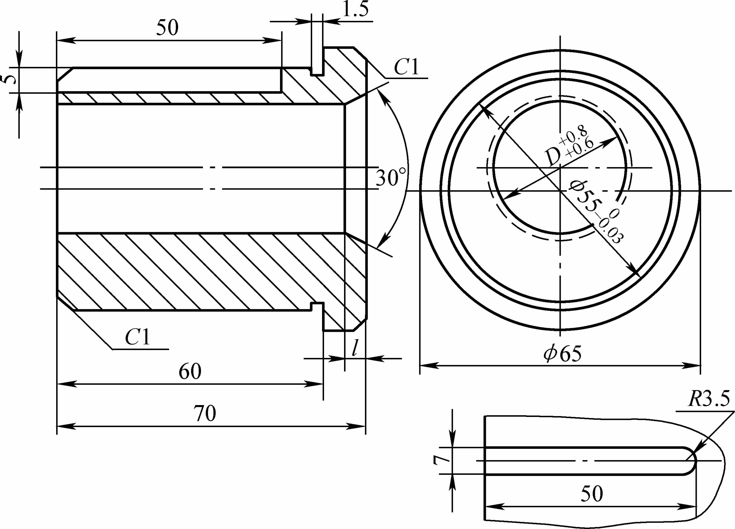
| Bar diameter d | D | l |
| 11 | 11.7 | 12 |
| 12 | 12.7 | 13 |
| 13 | 13.7 | 14 |
| 14 | 14. 7 | 15 |
| 15 | 16 | 16 |
| 16 | 17 | 17 |
| 17 | 18 | 18 |
| 18 | 19 | 19 |
| 19 | 20 | 20 |
| 20 | 21 | 21 |
| 21 | 22 | 22 |
| 22 | 23 | 23 |
| 23 | 24 | 24 |
| 24 | 25 | 25 |
| 25 | 26 | 26 |
| 26 | 27 | 10 |
| 27 | 28 | 10 |
| 28 | 29 | 5 |
| 29 | 30 | 5 |
| 30 | 31 | 4 |
| 31 | 32 | 4 |
| 32 | 33 | 4 |
IIII, Deviation of Blanks from Press
See Table 11 for deviation of blanks from press.
Table 11 Deviation of Blanks from Press (Unit: mm)
| Diameter of bar or side length of square material | Blank length | |||
| <300 | 300~600 | 600~1000 | >1000 | |
| <10 | ±0.5~±0.6 | ±0.6~±0.7 | ±0.7~±0.8 | ±0.8~±0.9 |
| 10~20 | ±0.6~±0.7 | ±0.7~±0.8 | ±0.8~±0.9 | ±0.9~±1.0 |
| 20~30 | ±0.7~±0.8 | ±0.8~±0.9 | ±0.9~±1.0 | ±1.0~±1.2 |
| 30~40 | ±0.8~±0.9 | ±0.9~±1.0 | ±1.0~±1.1 | ±1.2~±1.5 |

