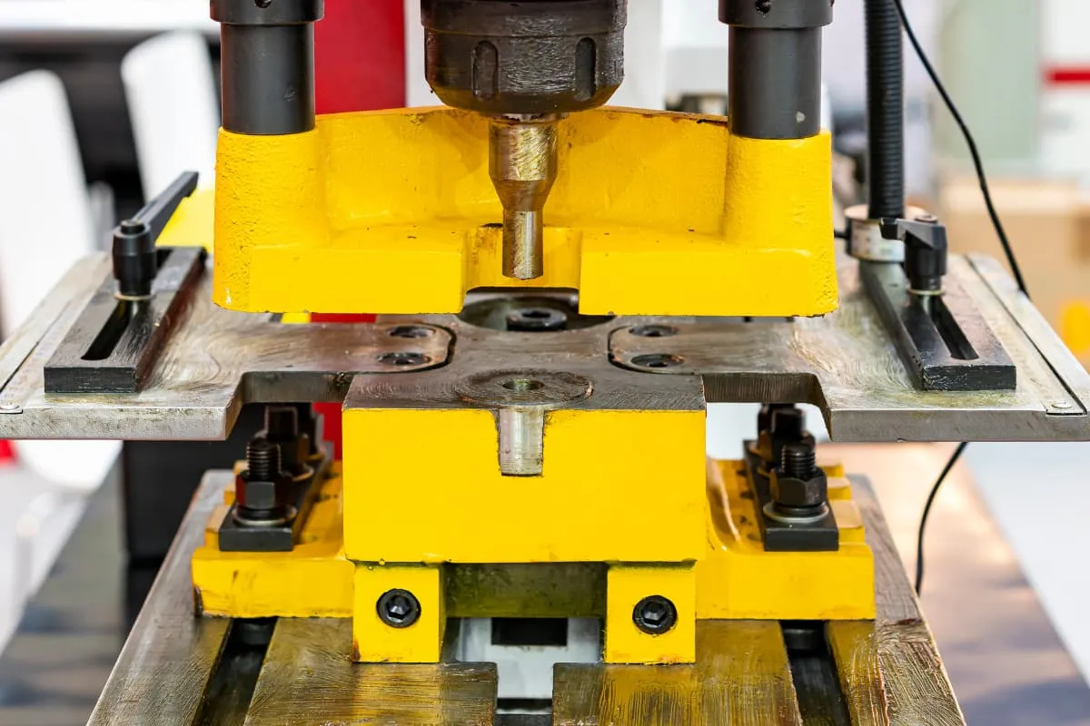
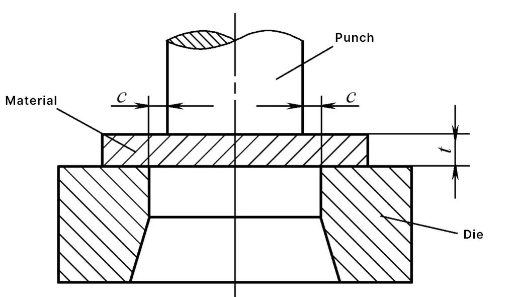
The clearance in punching refers to the distance between the gap of the punch and die edges, denoted by the symbol c (see Figure 1). Considering the precise meaning and practical function of the clearance, and to accommodate the requirements of mold making methods and clearance measurement methods, it is advisable to use a single-sided clearance.
Clearance is an extremely important parameter in punching processes and mold design. To make a correct assessment of whether the clearance is reasonable, it is necessary to first study the impact of clearance on the quality of punched parts (including cross-sectional quality, dimensional accuracy, and bending), mold life, and energy consumption, and to have a comprehensive understanding both qualitatively and quantitatively.
The punching clearance not only significantly affects the quality of the punched parts but also impacts the die life, punching force, stripping force, and ejection force. Therefore, clearance is a crucial parameter in the design of punching dies.
I. Impact of Clearance on the Quality of Punched Parts
The quality of punched parts is the main basis for evaluating reasonable clearance. After studying the impact of clearance on the quality of punched parts, appropriate clearance can be selected based on the technical requirements of the parts.
The quality of punched parts includes three aspects: cross-sectional quality, dimensional accuracy, and bending, which are now discussed separately.
1. Cross-sectional Quality
The impact of clearance on the cross-sectional quality of punching is shown in Figure 2. As shown in the figure, as the clearance increases, the bright band gradually decreases, and the collapse angle and burrs increase. Before the clearance reaches 20%t, the height of the burrs is small and changes little, this area is the stable burr zone. At smaller clearances, slight changes in clearance significantly affect the bright band, but when the clearance reaches a certain value (14%t~24%t), the impact on the bright band is smaller.
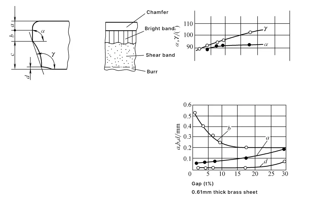
- a—Collapse angle
- b—Bright band
- c—Fracture zone
- d—Burr
- α—Angle of the bright band
- γ—Angle of the fracture zone
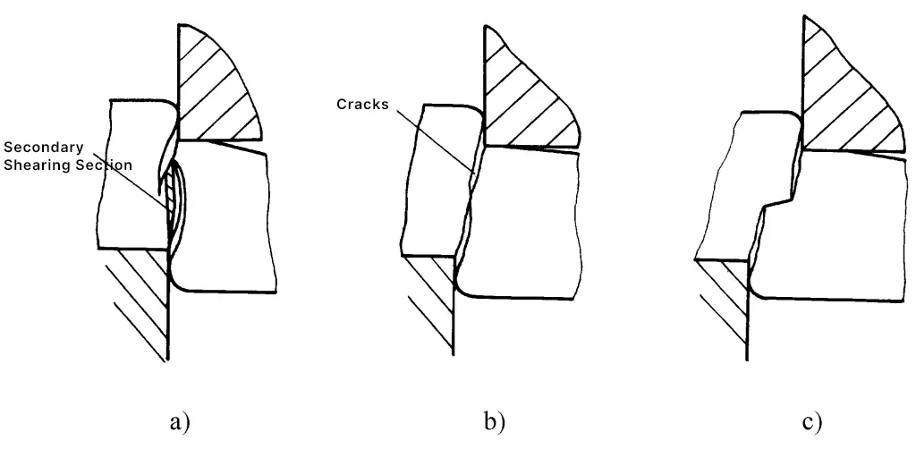
As the gap increases, the inclination of the fracture surface also increases. When the gap is appropriate, the upper and lower cracks meet and overlap in a line, at this time the shear surface is neat and tidy, the bright band accounts for about 1/3 of the plate thickness, and the collapse angle, burrs, and slope are also small (see Figure 3), which can meet the requirements of general punching parts.

a) Gap too small
b) Moderate gap
c) Excessive gap
Whether the gap is too large or too small, the cracks cannot align well (see Figure 4). When the gap is too small, the cracks at the edge of the convex die are misaligned outward (see Figure 4a), and the material enclosed between the upper and lower cracks will be sheared a second time, forming a second bright band and interlayer on the shear plane (see Figure 3a).
a) Gap too small
b) Moderate gap
c) Excessive gap
When the gap is too large, the cracks at the edge of the convex die are misaligned inward (see Figure 4c), the material undergoes significant stretching, the bright band is small, and the burrs’ collapse angle and slope increase, sometimes resulting in indentations (see Figure 3c).
When the gap is too small, it results in extruded burrs; when the gap is too large, it results in elongated burrs. When the edges of the convex and concave dies become blunt, burrs with enlarged bases appear as shown in Figure 5, which are difficult to remove and should be immediately sharpened.

When the gap is appropriate and the blade is sharp, the burrs are small, but it is impossible to completely avoid burrs whether in ordinary punching or precision punching (except for double-sided punching, i.e., burr-free cutting). Generally, stamped parts have burrs of varying degrees, but if the height of the burrs exceeds a certain limit, it will affect the quality and performance of the product.
Therefore, in actual production, the allowable height of burrs (refer to JB/T4129-1999 Stamping Parts Burr Height) should be specified as one of the quality inspection indicators for parts. Additionally, for stamping parts with strict quality requirements, it is necessary to adopt effective deburring methods.
2. Dimensional Accuracy
The dimensional accuracy of punched parts refers to the difference between the actual size of the punched parts and the basic size; the smaller the difference, the higher the accuracy. This difference includes two aspects of deviation: one is the deviation of the punched parts relative to the male or female die size, and the other is the manufacturing deviation of the die itself.
Assuming a certain precision in die manufacturing, the reasons for the deviation between the punched parts and the male and female die sizes are due to the material being pushed out from the female die (blanking parts) or unloaded from the male die (punching parts), caused by elastic recovery during the punching process due to compression deformation, fiber elongation, and doming. Additionally, the elastic deformation and wear of the male and female dies under the impact of punching force also cause changes in the dimensions of the punched parts.
When measuring the deviation between the dimensions of punched parts and male and female dies, the reference for blanking parts is the female die, and for punching parts, it is the male die.
- Blanking: ΔD = Outer diameter of punched part – Diameter of female die hole
- Punching: ΔD = Punching diameter – Outer diameter of male die
Ideally, during blanking, the outer diameter of the workpiece should match the diameter of the female die hole, and during punching, the punching diameter should match the outer diameter of the male die (i.e., ΔD should be zero), achieving the highest dimensional accuracy.
However, due to the reasons mentioned above, deviations are inevitable. Factors affecting the deviation value include: punching gap; material properties, thickness, and rolling direction; and the shape and size of the workpiece, among which the gap is the main influencing factor.
Under different gap conditions, there will be positive and negative deviations. Generally, the result of rebound makes the hole diameter of the punched part smaller (ΔD is a negative value), and the outer diameter of the blanking part larger (ΔD is a positive value); when the gap is large, the result of rebound makes the hole diameter of the punched part larger (ΔD is a positive value), and the outer diameter of the blanking part smaller
(ΔD is a negative value).
Figure 6 shows the impact of the gap on the size deviation of the blanking parts. When the gap is within 5% of the plate thickness, as the gap increases, the outer diameter size of the blanking parts decreases. From 5% to 25% of the plate thickness, the size of the workpiece does not change with the increase of the gap. When the gap exceeds 25% of the plate thickness, the size of the workpiece will decrease again. However, when the gap is below 2% of the plate thickness, the outer diameter size of the workpiece is actually larger than the size of the die hole.
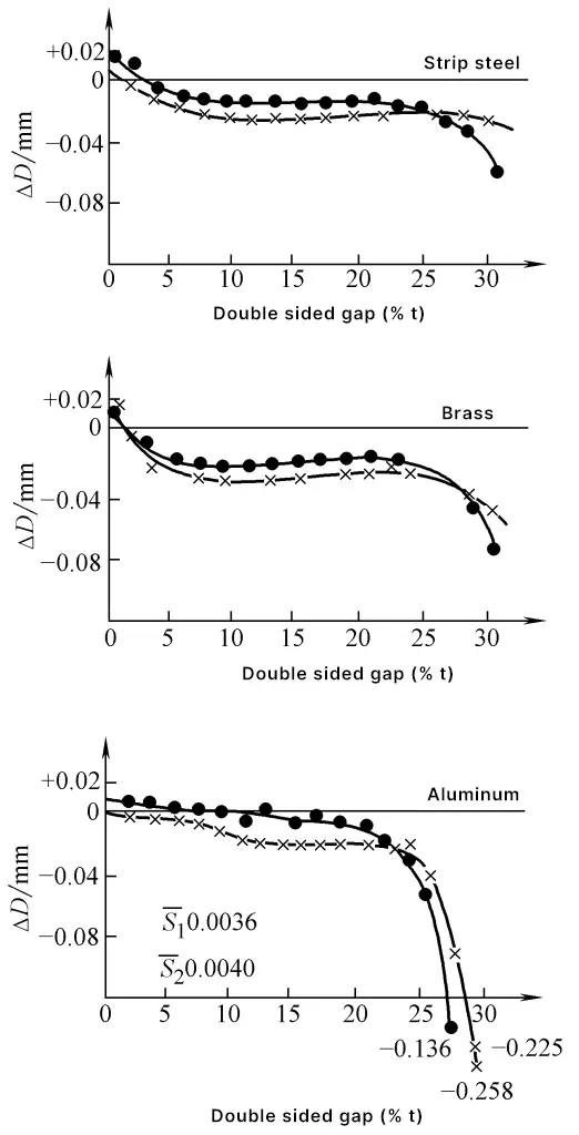
- S 1 , S 2 — Average value of size flatness
- —•—•— Rolling direction (S 1 )
- —×—×— Perpendicular to the rolling direction (S 2 )
- ΔD = Outer diameter of the punched part – Die hole diameter
Figure 7 shows the impact of the gap on the size deviation of the punched holes. When the gap is below 5% of the plate thickness, the size of the hole is smaller than the outer diameter of the punch. As the gap increases, the hole size increases. Moreover, when the gap is around 15% of the plate thickness, the size of the hole is the largest, and then as the gap increases, the size of the hole decreases inversely.
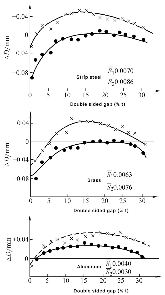
S 1 , S 2 — Average flatness of size
—•—•— Rolling direction (S 1 )
—×—×— Perpendicular to the rolling direction (S 2 )
ΔD = Punching diameter – Punch outer diameter
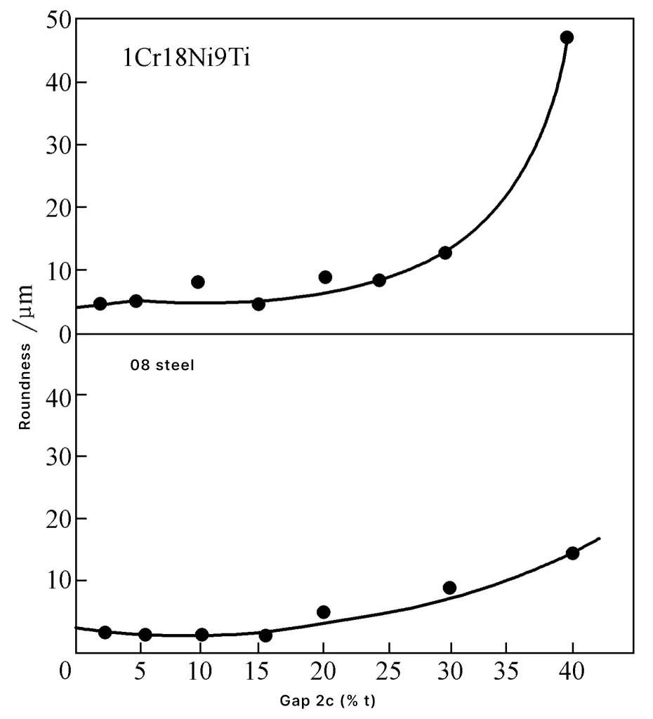
Additionally, when punching circular profiles, due to the eccentricity of the punch and die, the deflection of the press, the rolling direction of the plate, the width of the punching overlap, and the presence of a clamping device, the punched parts will have a certain degree of ovality. Figure 8 shows the impact of the gap on the ovality of the punched parts, with a significant increase in ovality when the gap is too large.
3. Degree of bending
In the punching process, the material beneath the punch bends due to the bending moment. If the deformation reaches the range of plastic bending, the workpiece will retain some residual bending deformation even after springback.
The relationship between the degree of bending and the gap is shown in Figure 9. Usually, the larger the gap, the more pronounced the bending, but sometimes with a small gap, since the punched part is larger than the die hole, the punched part can also exert a squeezing effect on the side of the die, resulting in greater bending. The degree of bending is also related to the material properties and thickness (see Figures 9 and 10).


1—t=0.5mm (D d /t =40)
2—t=1.0mm (D d /t =20)
3—t=1.6mm (D d /t =12.5)
To reduce bending, a reverse pressure plate can be added under the punch. When high flatness of the stamped parts is required, an additional leveling process must be added.
II. The impact of clearance on die life
Die life is calculated by the number of qualified parts produced, one is the life between two grindings, and the other is the total life after complete wear.
The wear process of the blanking die can be divided into three stages (see Figure 11): initial wear, middle wear, and late wear.
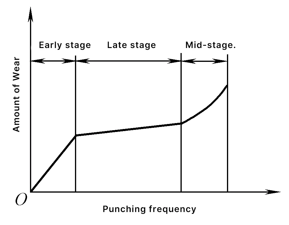
Initial wear, where wear is mainly concentrated at the cutting edge, due to excessive pressure concentration here, the sharp cutting edge is prone to rolling or chipping, and wear is rapid.
Middle wear, also known as stable wear, the cutting edge is slightly rounded, pressure concentration is alleviated, entering normal friction wear, wear is slow. The longer the middle wear period, the higher the die life.
Late wear, also known as excessive wear, friction wear reaches the fatigue limit, entering a phase of rapid wear increase, wear is fast, at this time grinding should be performed.
According to the wear parts of the punch and die, it can be divided into: end face wear and side face wear. Figure 12 shows the changes in the shape of the cutting edge after different numbers of blanking.

The main factors affecting the life of the mold include: chemical composition of the mold material, hardness and surface strengthening treatment, surface roughness of the precision machined part of the mold working part, mold clearance, rationality of mold structure, constraint method of the material being processed and the guiding method of the upper and lower molds, chemical composition of the material being processed, mechanical properties and hardness state, surface treatment of the material (insulating coating of inorganic, semi-organic, organic substances, etc.), lubrication and cooling conditions, the edge and radius of the contour of the stamped parts, precision and rigidity of the press, and stamping speed, etc.
Among the factors affecting the life of the stamping die, clearance is one of the important factors. Figure 13 shows the effect of clearance on blade wear after 100,000 stamping operations.
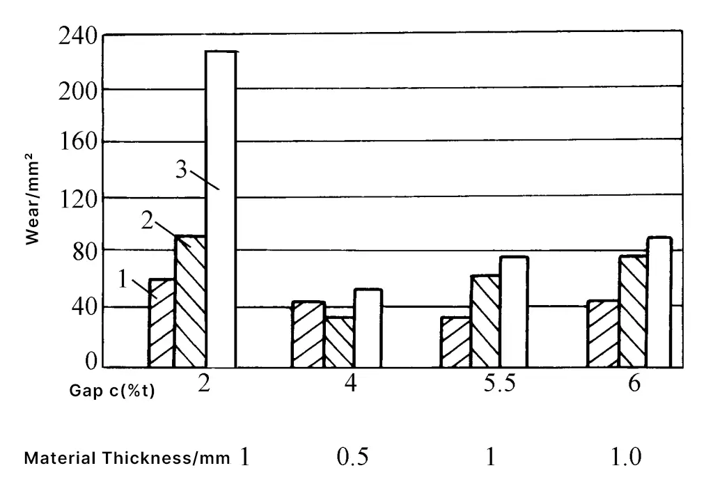
- Shearing conditions: No pressure plate
- Mold material: Mn steel
- Quenching hardness: 59HRC
- Mold shape: ϕ8 round convex mold
- Material being processed: Soft steel plate
- Material thickness: 1mm
- 1-Punch face wear
- 2-Die face wear
- 3-Punch side wear
The situation indicates that under small clearance, the shearing conditions are harsh, compression extrusion is severe, friction increases dramatically, and wear increases, especially side wear is more obvious. Furthermore, at small clearances, die swelling, punch breakage (small punches), and abnormal damage such as mutual biting between punch and die can occur. Moreover, too small a clearance can cause increased friction and higher temperatures.
When the compression extrusion stress is high, it is easy to produce adhesion between the mold and the material, which brings a lot of trouble to production.
In addition, uneven clearance is also detrimental to the life of the mold; compared to uniform clearance, wear significantly increases (see Figure 14).
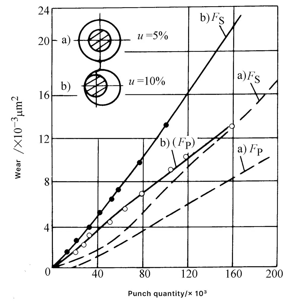
- Shape: Circular
- Mold 210Cr12
- (w(C)=2.1%, w(Cr)=12%)
- Material being processed: Electrical steel plate 0.5mm thick
- F S : Punch wear
- F P : Die wear
Mass production practice shows that using a large clearance can significantly improve the life of the mold, generally 2~3 times longer than with a small clearance, and in some cases up to 6~7 times, with very significant economic benefits. However, too large a clearance not only reduces the quality of the workpiece cross-section, increases burrs and bending, but also makes the wear of the punch and die end faces the main contradiction.
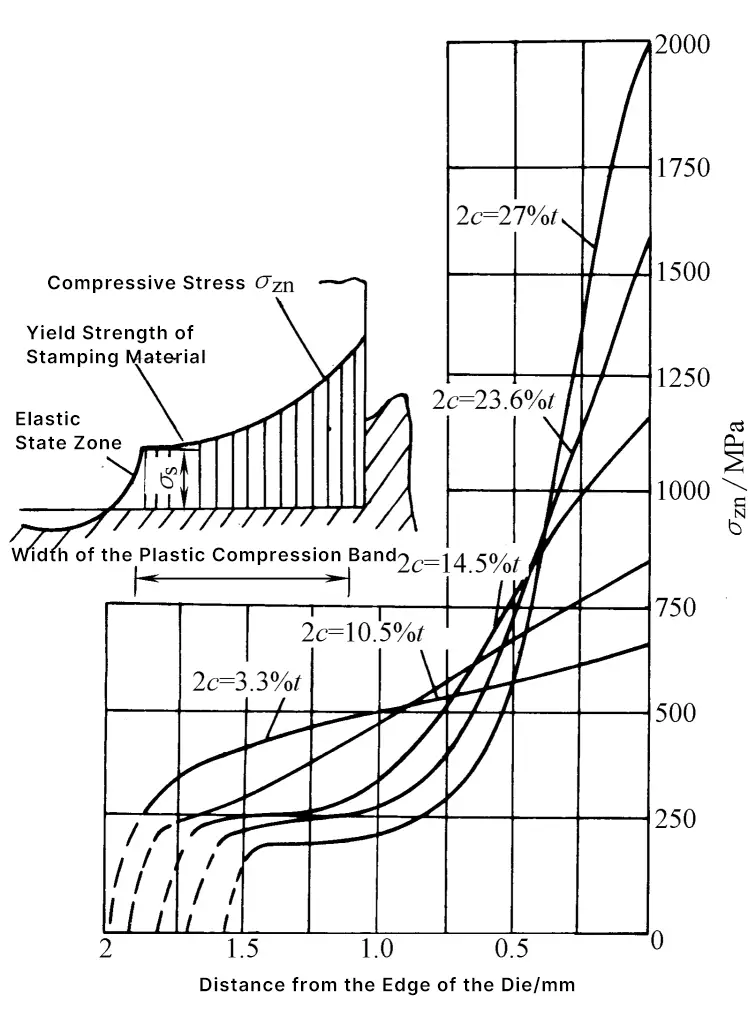
Soviet scholars calculated the distribution of compressive stress near the edge of the punch and die end faces based on the compression deformation of the plastic pressing band of the punched parts (see Figure 15), and pointed out that with a small clearance, the friction on the sides of the punch and die is great, and side wear is severe during frequent punching, unloading, and pushing processes.
But too large a clearance increases the concentrated stress at the edges of the punch and die end faces, causing the compressive stress to increase sharply, especially forming a large peak at the edge of the blade, causing the blade edge to quickly yield and deform, losing its sharpness. Therefore, it also increases the punching force, further causing the blade edge to wear and blunt more quickly, reducing the life of the mold.
III. The impact of clearance on energy consumption
From the perspective of saving energy and effort, choosing medium and large clearances will yield good results, at this time, the punching force, unloading force, pushing force, and punching work are all smaller.
1. Punching force
Generally speaking, as the gap increases, the compressive stress in the shear zone decreases and the tensile stress increases, making cracks more likely to occur and reducing the shear strength. The punching force is proportional to the shear strength, so it also decreases proportionally as the gap increases. However, when the gap is large enough, since the upper and lower cracks do not coincide, the decrease in shear strength is very slight, and there may even be a rebound trend (see Figure 16).

- 1—t=0.5mm (D d /t=40)
- 2—t=1.0mm (D d /t=20)
- 3—t=1.6mm (D d /t=12.5)
2. Unloading force and ejector force
Figure 17 shows the relationship curve between the gap and unloading force. Whether it is soft steel, stainless steel, brass, or aluminum alloy, the unloading force reaches its minimum value when the gap is about 20% of the material thickness. The unloading force increases sharply when the gap is less than 10% or more than 30% of the material thickness.

When the gap is greater than 10% to 15% of the material thickness, after the punching is completed, the size of the punched part shrinks due to tensile deformation and springback, no longer blocking in the die, making the ejector force nearly zero.
3. Punching work
Punching work refers to the area enclosed under the force-stroke curve (indicator diagram). Punching work is the main basis for selecting or checking the power of the main motor of the press.
Punching work fluctuates slightly with changes in the gap. If the gap is too small or too large, the punching work will increase. When the gap is appropriate, making the upper and lower cracks meet and coincide, the punching work is minimized (see Figure 18).

Material: 3.3mm thick brass plate material fixed round hole punching
IV. Determination of reasonable clearance
The clearance between the punch and die greatly affects the sectional quality, dimensional accuracy, die life, and energy consumption of the punched parts. When designing the die, it is essential to choose a reasonable clearance. In summary, balancing the impact of clearance on the quality, dimensional accuracy, die life, and energy consumption of the punched parts, there is no one reasonable clearance value that meets all requirements.
Moreover, the die wears during use, and the clearance cannot remain fixed but always varies within a certain range. Additionally, there is some difference between the static clearance in the assembled state of the die and the dynamic clearance in the working state.
Therefore, in actual production, a suitable range is usually selected as the reasonable clearance. The lower limit of this range is called the minimum reasonable clearance c min , and the upper limit is called the maximum reasonable clearance c max . Considering that wear on the die will increase the clearance, the minimum reasonable clearance value should be used when designing and manufacturing new dies.
Methods for determining reasonable clearance include:
1. Theoretical determination method
The main basis of the theoretical determination method is to ensure crack coincidence to obtain a good shearing section. Figure 19 shows the instantaneous state of crack initiation at the beginning of the punching process. The clearance c can be determined from triangle △ABC in the figure.
c=(t-h0 )tanβ=t(1-h0 /t)tanβ
Where
- h 0 – punch penetration depth (mm);
- t-Material thickness (mm);
- β-Angle between the maximum shear stress direction and the vertical line (°).
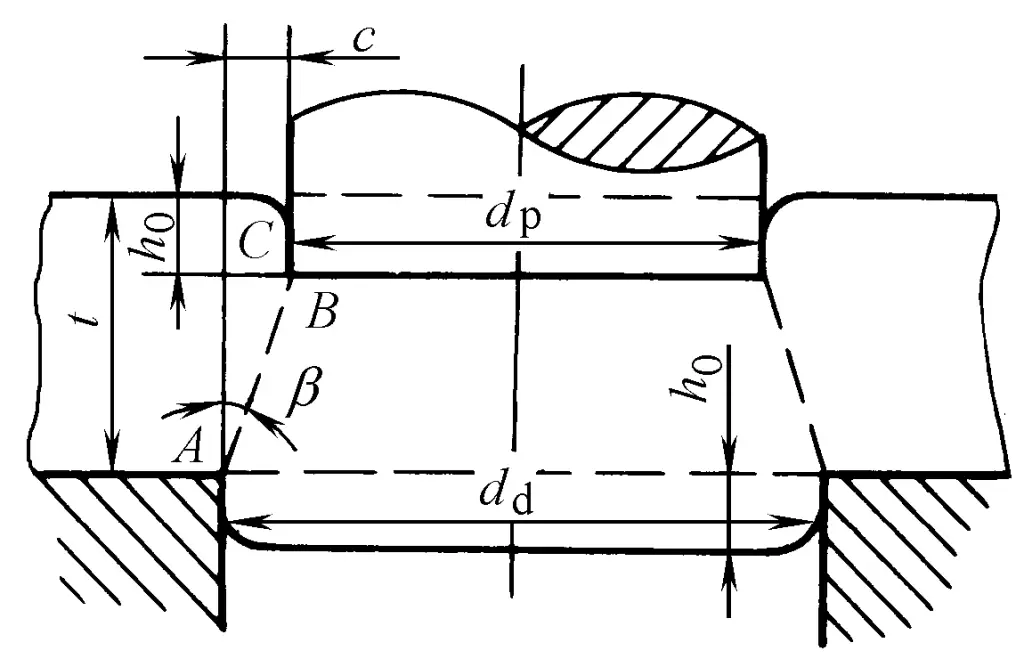
It can be seen from the above formula: c=f(t, h 0 /t, β), and h 0 /t, β is related to material properties (see Table 1), therefore, the main factors affecting the gap value are material properties and thickness. The harder and thicker the material, the larger the reasonable gap value.
Table 1 h 0 /t and β values
| Material | h0/t | β /(°) | ||
| Annealing | Hardening | Annealing | Hardening | |
| Soft steel, pure copper, soft brass | 0.5 | 0.35 | 6 | 5 |
| Medium-hard steel, hard brass | 0.3 | 0.2 | 5 | 4 |
| Hard steel, hard bronze | 0.2 | 0.1 | 4 | 4 |
2. Empirical determination method
The clearance values used in the past were selected mainly based on dimensional accuracy, and have generally been proven to be too small and not widely applicable. In some cases, the dies made with these clearance values produce parts with double bright bands on the cross-section and significant burrs.
Also, due to the high friction between the die and the material, severe heating occurs, causing the material to adhere to the cutting edge, accelerating the wear of the cutting edge, and reducing the life of the die. There are also frequent occurrences of abnormal damage such as die swelling and punch breaking.
Based on recent research results and production experience, and referring to the clearance standards of the United States, Germany, Japan, and the former Soviet Union, the “Punching Clearance” national standard GB/T16743-1997 was established in 1997 (now using the new standard GB/T16743-2010).
This standard, based on the principle of “determining clearance by quality”, divides the punching clearance of metal materials into three categories according to the main factors such as the dimensional accuracy of the punching parts, cross-sectional quality, die life, and energy consumption, to meet the technical requirements of different punching parts and to select the clearance rationally and targetedly. This ensures the dimensional accuracy and cross-sectional quality of the punching parts while achieving the corresponding die life.
When selecting the punching clearance, one should first determine the intended clearance category according to Table 2, based on the technical requirements, usage characteristics, and production conditions of the punching parts, and then select the corresponding ratio of that clearance category from Table 3. After calculation, the appropriate clearance value can be obtained.
Table 2 Classification of Metal Material Punching Clearances
| Basis of Classification | Class I | Class II | Class III | ||
| Quality of the Punching Section | Characteristics of the Shear Surface |  |  |  | |
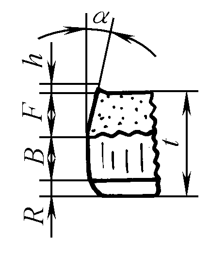 | Collapsed Corner Height R | (4~7)%t | (6~8)%t | (8~10)%t | |
| Bright Band Height B | (35~55)%t | (25~40)%t | (15~25)%t | ||
| Fracture Band Height F | Small | Medium | Large | ||
| Burr height h | General | Small | General | ||
| Fracture angle α | 4~7° | >7~8° | >8~11° | ||
| Precision of blanking parts | Flatness | 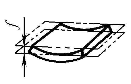 | Slightly Smaller | Small | Larger |
| Size Precision | Blanking Piece | Close to Die Size | Slightly Smaller than Die Size | Smaller than Die Size | |
| Punched Piece | Close to Punch Size | Slightly larger than the punch size | Larger than the punch size | ||
| Mold life | Lower | Longer | Longest | ||
| Energy consumption | Punching force | Larger | Small | Minimum | |
| Unloading, pushing force | Larger | Minimum | Small | ||
| Punching power | Larger | Small | Slightly smaller | ||
| Applicable occasions | When high quality and dimensional accuracy of the punched section are required, use a small clearance. The die life is relatively short. | When the quality and dimensional accuracy of the punched section are generally required, use a medium clearance. Due to the small residual stress, it can reduce the occurrence of fractures, suitable for workpieces that undergo further plastic deformation. | When the quality and dimensional accuracy of the punched section are not high, prioritize using a large clearance to help improve the die life. | ||
Table 3 Metal Material Punching Clearance Values
| Material | Shear Strength τb/ MPa | Initial Clearance (Single Side Clearance) (% t) | ||
| Type I | Type II | Type III | ||
| Low carbon steel 08F, 10F, 10, 20, Q235-A | ≥210~400 | 3.0~7.0 | >7.0~10.0 | >10.0~12.5 |
| Medium carbon steel 45 Stainless steel 1Cr18Ni9Ti, 4Cr13 Expansion alloy (Kovar) 4J29 | ≥420~560 | 3.5~8.0 | >8.0~11.0 | >11.0~15.0 |
| High carbon steel T8A, T10A Spring steel 65Mn | ≥590~930 | 8.0~12.0 | >12.0~15.0 | >15.0~18.0 |
| Pure aluminum 1060, 1050A, 1035, 1200 Aluminum alloy (soft) 5A21 Brass (soft) H62 Pure copper (soft) T1, T2, T3 | ≥65~255 | 2.0~4.0 | 4.5~6.0 | 6.5~9.0 |
| Brass (hard) H62 Lead brass HPb59-1 Pure copper (hard) T1, T2, T3 | ≥290~420 | 3.0~5.0 | 5.5~8.0 | 8.5~11.0 |
| Aluminum alloy (hard) 5A12 Tin phosphor bronze QSn4-4-2.5 Aluminum bronze QA17 Beryllium bronze QBe2 | ≥225~550 | 3.5~6.0 | 7.0~10.0 | 11.0~13.0 |
| Magnesium alloy MB1, MB8 | ≥120~180 | 1.5~2.5 | ||
| Electrical silicon steel D21, D31, D41 | 190 | 2.5~5.0 | > 5.0~9.0 | |
When high quality and precision of the cross-section of the stamped parts are required, a small clearance should be used, but the die life is shorter. When the quality and precision requirements of the cross-section of the stamped parts are moderate, a medium clearance should be used, which consumes less power and extends the die life.
When the quality and precision requirements of the cross-section of the stamped parts are not high, it is advisable to prioritize using a large clearance, which has the prominent advantage of the longest die life, and the stamped parts have less expansion force in the die, allowing the use of straight cylinder dies, thus possibly cutting both male and female dies with wire cutting, “one billet for dual use” can save expensive die steel, and with the small unloading force simplifying the unloading device, the stamping force is low, improving the working conditions of the die, and has obvious economic benefits.
The clearance for stamping can only be listed in a data table based on the main influencing factors. However, considering the large differences in production conditions and active technological factors, sometimes it is necessary to flexibly handle issues in conjunction with actual production conditions, appropriately adjusting the clearance values. This standard summarizes the experience in this area.
This standard also recommends the punching clearance values for commonly used non-metallic materials, see Table 4.
Table 4 Non-metallic material punching clearance values
| Material | Initial clearance (single side clearance) (% t) |
| Phenolic laminate | 1.5 – 3.0 |
| Asbestos board | |
| Rubber sheet | |
| Organic glass sheet | |
| Epoxy phenolic glass cloth | |
| Red cardboard | 0.5 – 2.0 |
| Cardboard | |
| Tape board | |
| Mica sheet | 0.25 – 0.75 |
| Leather | |
| Paper | |
| Fiberboard | 2.0 |
| Felt | 0~0.2 |
Additionally, two types of die clearance values are recommended. In sectors such as radio, instrumentation, and precision machinery, where high dimensional accuracy of stamped parts is required, the smaller clearance values listed in Table 5 can be used. In sectors like automotive, agricultural machinery, and hardware daily goods, where the tolerance range for stamped part dimensions is larger, the larger clearance values listed in Table 6 can be adopted.
Table 5 Initial single-sided clearance c for die cutting (unit: mm)
| Material thickness / mm | Soft aluminum | Pure copper, brass, soft steel (0.08~0.2)%c | Hard aluminum alloy, medium-hard steel (0.3~0.4)%c | Hard steel (0.5~0.6)%c | ||||
| Cmin | Cmax | Cmin | Cmax | Cmin | Cmax | Cmin | Cmax | |
| 0.2 | 0.004 | 0.006 | 0.005 | 0.007 | 0.006 | 0.008 | 0.007 | 0.009 |
| 0.3 | 0.006 | 0.009 | 0.008 | 0.01 | 0.009 | 0.012 | 0.01 | 0.013 |
| 0.4 | 0.008 | 0.012 | 0.01 | 0.014 | 0.012 | 0.016 | 0.014 | 0.018 |
| 0.5 | 0.01 | 0.015 | 0.012 | 0.018 | 0.015 | 0.02 | 0.018 | 0.022 |
| 0.6 | 0.012 | 0.018 | 0.015 | 0.021 | 0.018 | 0.024 | 0.021 | 0.027 |
| 0.7 | 0.014 | 0.021 | 0.018 | 0.024 | 0.021 | 0.028 | 0.024 | 0.031 |
| 0.8 | 0.016 | 0.024 | 0.02 | 0.028 | 0.024 | 0.032 | 0.028 | 0.036 |
| 0.9 | 0.018 | 0.027 | 0.022 | 0.031 | 0.027 | 0.036 | 0.031 | 0.04 |
| 1 | 0.02 | 0.030 | 0.025 | 0. 035 | 0. 030 | 0.04 | 0.035 | 0.045 |
| 1.2 | 0.025 | 0.042 | 0. 036 | 0.048 | 0.042 | 0.054 | 0.048 | 0.060 |
| 1.5 | 0.038 | 0.052 | 0.045 | 0.06 | 0. 052 | 0. 068 | 0. 060 | 0.075 |
| 1.8 | 0.045 | 0.063 | 0.054 | 0.072 | 0.063 | 0.081 | 0.072 | 0.09 |
| 2 | 0.05 | 0.070 | 0.06 | 0.08 | 0.07 | 0.09 | 0.080 | 0.1 |
| 2.2 | 0.066 | 0.088 | 0.077 | 0.099 | 0.088 | 0.110 | 0.099 | 0.121 |
| 2.5 | 0.075 | 0.1 | 0.088 | 0.112 | 0.100 | 0.125 | 0.112 | 0.138 |
| 2.8 | 0.084 | 0.112 | 0.098 | 0.126 | 0.112 | 0.14 | 0. 126 | 0.154 |
| 3 | 0.090 | 0.120 | 0.105 | 0.135 | 0.12 | 0.15 | 0.135 | 0.165 |
| 3.5 | 0.122 | 0.158 | 0.14 | 0.175 | 0.158 | 0.192 | 0.175 | 0.21 |
| 4 | 0.14 | 0.18 | 0.16 | 0.2 | 0.18 | 0.22 | 0.2 | 0.24 |
| 4.5 | 0.158 | 0.202 | 0.18 | 0.225 | 0.202 | 0.245 | 0.225 | 0.270 |
| 5 | 0.175 | 0.225 | 0.2 | 0.25 | 0.225 | 0.275 | 0.250 | 0.3 |
| 6 | 0.24 | 0.3 | 0.27 | 0.33 | 0.300 | 0.360 | 0.330 | 0.390 |
| 7 | 0.28 | 0.350 | 0. 315 | 0.385 | 0.350 | 0.42 | 0.385 | 0.455 |
| 8 | 0.360 | 0.44 | 0.4 | 0.48 | 0.440 | 0.52 | 0.48 | 0.560 |
| 9 | 0.435 | 0.495 | 0.45 | 0.54 | 0.495 | 0.585 | 0.54 | 0.63 |
| 10 | 0.45 | 0.550 | 0.500 | 0.600 | 0.55 | 0.650 | 0.600 | 0.700 |
Note:
1. The minimum value of the initial clearance is equivalent to the nominal value of the clearance.
2. The maximum value of the initial clearance takes into account the added value due to manufacturing tolerances of the male and female dies.
3. During use, due to wear on the working parts of the mold, the clearance will increase, thus the maximum usage value of the clearance should exceed the listed values.
Table 6 Initial single-sided clearance c for punching dies (unit: mm)
| Material Thickness / mm | 08,10,35 09Mn, Q235 | Q345 (16Mn) | 40,50 | 65Mn | ||||
| Cmin | Cmax | Cmin | Cmax | Cmin | Cmax | Cmin | Cmax | |
| Less than 0.5 | Minimal Clearance | |||||||
| 0.5 | 0.02 | 0. 030 | 0.02 | 0.03 | 0.02 | 0.030 | 0.020 | 0.03 |
| 0.6 | 0.024 | 0.036 | 0.024 | 0.036 | 0.024 | 0.036 | 0.024 | 0.036 |
| 0.7 | 0.032 | 0.046 | 0.032 | 0.046 | 0.032 | 0.046 | 0.032 | 0.046 |
| 0.8 | 0.036 | 0.052 | 0.036 | 0.052 | 0.036 | 0.052 | 0.032 | 0.046 |
| 0.9 | 0.045 | 0.063 | 0.045 | 0.063 | 0.045 | 0.063 | 0.045 | 0.063 |
| 1 | 0.05 | 0.07 | 0.05 | 0.07 | 0.05 | 0.07 | 0.045 | 0.063 |
| 1.2 | 0.063 | 0.090 | 0.066 | 0.09 | 0.066 | 0.090 | ||
| 1.5 | 0.066 | 0.12 | 0.085 | 0.12 | 0.085 | 0.120 | ||
| 1.75 | 0.11 | 0.16 | 0.11 | 0.16 | 0.11 | 0.160 | ||
| 2 | 0.123 | 0.18 | 0.13 | 0.19 | 0.13 | 0.19 | ||
| 2.1 | 0.13 | 0.19 | 0.14 | 0.2 | 0.14 | 0.2 | ||
| 2.5 | 0.18 | 0.25 | 0.19 | 0.27 | 0.19 | 0.27 | ||
| 2.75 | 0.2 | 0.28 | 0.21 | 0.3 | 0.21 | 0.300 | ||
| 3 | 0.23 | 0. 320 | 0.24 | 0.33 | 0.24 | 0.33 | ||
| 3.5 | 0.27 | 0. 370 | 0.29 | 0.39 | 0.29 | 0.390 | ||
| 4 | 0.32 | 0.44 | 0.34 | 0.46 | 0.340 | 0.460 | ||
| 4.5 | 0.360 | 0.500 | 0.340 | 0.48 | 0.390 | 0.52 | ||
| 5.5 | 0.470 | 0.640 | 0.39 | 0.550 | 0.49 | 0.660 | ||
| 6 | 0.540 | 0.720 | 0.42 | 0.600 | 0.57 | 0.75 | ||
| 6.5 | 0.47 | 0.650 | ||||||
| 8 | 0.6 | 0.840 | ||||||
V. Selection Principle of Punch and Die Clearance Values
Analysis of the stamping process reveals that there is currently no fixed clearance value that can satisfy all the requirements for optimal section quality, highest dimensional accuracy, minimal warping deformation, longest die life, and minimal punching force, unloading force, and part ejection force.
Therefore, in actual stamping production, a clearance range is primarily determined based on factors such as section quality, dimensional accuracy, anddie life. As long as the clearance is within this range, acceptable stamped parts and a longer die life can be achieved.
This range is known as the reasonable clearance, with the minimum value termed the minimum reasonable clearance and the maximum value as the maximum reasonable clearance. When designing and manufacturing, it should be taken into account that wear during use will increase the clearance between the punch and die; thus, it’s generally best to determine the die clearance based on the minimum reasonable clearance value.
The smaller the selected clearance during design, the higher the manufacturing and assembly precision required, which correspondingly increases costs. A smaller clearance also demands higher strength and precision from the die, resulting in a shorter lifespan and a higher likelihood of maintenance. Consequently, the level of punching clearance is typically chosen based on the following criteria:
(1) Material shear strength
Materials with lower shear strength have better stretch forming capabilities and are more prone to burring, so the clearance should be on the smaller side. For instance, the punching clearance for copper materials of medium hardness is 70% of that for steel materials of the same thickness, and 60% for aluminum materials.
(2) Workpiece precision requirements
Products for the electronics and household appliance industries require high precision, while those for outdoor products, electrical, and agricultural machinery industries have lower precision requirements. Accordingly, the die clearance can be larger.
(3) Workpiece area and edge length
Larger workpiece areas or those with long edges tend to accumulate greater errors during die manufacturing and assembly, so a larger die clearance should be chosen. (An exception is made for rectangular blanking dies with long edges because during stamping, the workpiece exerts a compressive force on the concave die, causing straight-line die edges to expand.)
(4) Position in the process flow
When the burrs produced by punching adversely affect subsequent operations or the final product, the die clearance should be smaller. If there is no adverse impact, a larger clearance is preferable.
(5) Die structure
When the die structure is constrained by the material shape and cannot ensure optimal punch and die clearance (such as with tube cutting or punching dies on slanted surfaces), a larger clearance should be selected.
VI. Rapid Calculation of Clearance Values Between Punch and Die for Economy-Grade Workpieces
In everyday production, economy-grade workpieces account for more than 80% of the total workload. If the workpiece geometry is an external polygon, or has internal protrusions or slots with a width no less than 12 times the material thickness (12t), it can still be treated as an economy-grade workpiece. In such cases, the bilateral clearance (C) between the punch and die is calculated as 10% of the material thickness: C = 0.1t.
If the calculated clearance is less than 0.02mm, it should be processed as if there were no clearance, meaning the punch should be designed not to enter the die.
A method for clearance-free punching involves using multiple layers of material for stacking punches. This technique is suitable for blanking dies but should be approached with caution for punching dies.
Clearance-free punching requires high precision in the mechanical press movement. The clearance between the slide and the guide should be between 0.005mm and 0.015mm, and the axial clearance between the connecting rod and the spherical cap should not exceed 0.02mm; it must not be too loose. The work environment should be clean and tidy.
A small amount of lubricant should be added during punching, and care should be taken to prevent foreign particles or dust from contaminating the materials and lubricant.
VII. Principles for Selecting Clearance Directions
1) For blanking, use the die size as the reference, with the punch size being the die size minus the clearance value.
2) For punching, use the punch size as the reference, with the die size being the punch size plus the clearance value.

