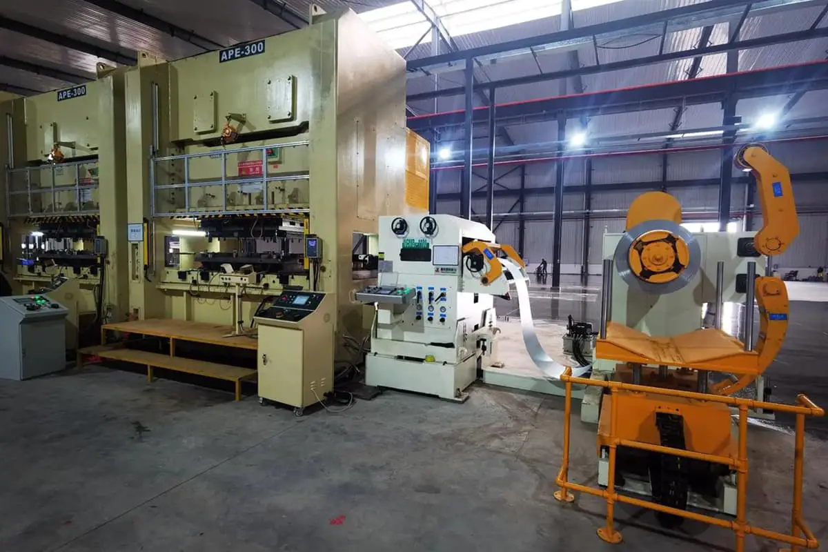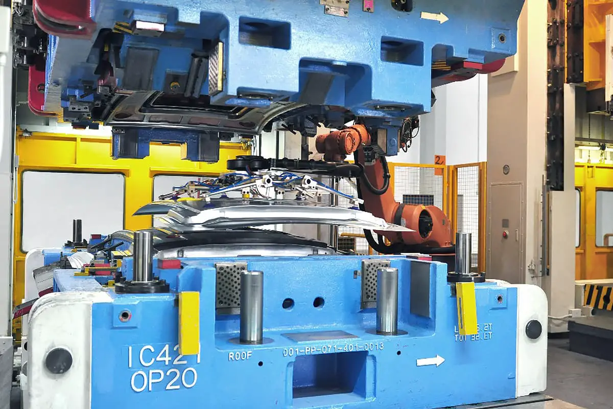
I. Common blanking methods and their applications
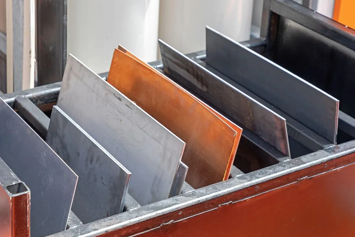
The forms of materials used in sheet metal processing mainly include plates, profile steel, and pipe materials. To process the required shapes and other requirements of sheet metal components, the raw materials should first be cut into blanks as needed. This process is called blanking and is often the first step in sheet metal processing.
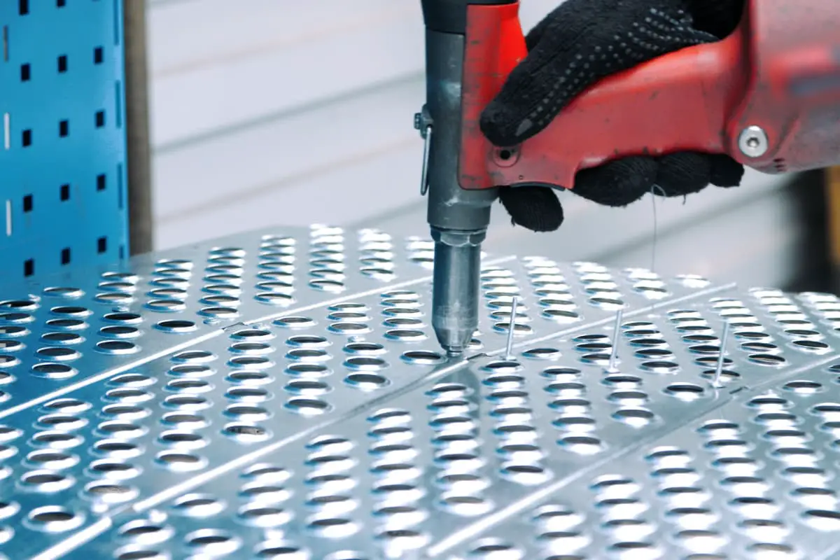
There are many methods of blanking. The main types used in production include shearing, punching, cutting, and machining. Table 1 shows common blanking methods and their applications.
Table 1 Common blanking methods and their applications
| Classification | Method | Equipment | Application |
| Shearing | Manual shearing | Hand shears, handheld vibrating shears, manual guillotine shears | Used for straight and curved processing of plates such as low carbon steel, aluminum and its alloys, copper and its alloys, cardboard, bakelite, and plastic sheets with thickness t≤4mm. The processed parts have low precision and production efficiency but low cost. |
| Machine straight shearing | Guillotine shears | Used for shearing materials such as low carbon steel, aluminum and its alloys, copper and its alloys, cardboard, bakelite, and plastic sheets. It has high shearing force, high productivity, and is used for the straight shape processing of plates. | |
| Slant shears | Used for shearing materials such as low carbon steel, aluminum and its alloys, copper and its alloys, cardboard, bakelite, and plastic sheets. It has lower shearing force, suitable for medium or large straight shapes, large arcs, and beveling of plates, with a shearing thickness of up to 40mm. | ||
| Small step shearing | Vibrating shears | Used for shearing materials such as low carbon steel, aluminum and its alloys, copper and its alloys, cardboard, bakelite, and plastic sheets. Suitable for complex curves, perforations, and notches, and can also shear titanium alloys. | |
| Disc rolling shears | Straight circle rolling shears | Used for shearing materials such as low carbon steel, aluminum and its alloys, copper and its alloys, cardboard, bakelite, and plastic sheets. Suitable for shearing strips, straight lines, and arcs with relatively low precision. There are burrs on the cut edges, suitable for small batch production of small and medium-sized parts, with a shearing thickness of up to 30mm. | |
| Down-slant rolling shears | Shear straight lines and arcs (R small), with relatively low precision, and burrs on the cut edges, with a shearing thickness of up to 30mm. | ||
| Full-slant rolling shears | Complex curves, with relatively low precision, and burrs on the cut edges, with a shearing thickness of up to 20mm, precision ±1mm. | ||
| Punching | Punching | Press | Commonly used for blanking, punching, cutting off, and notching sheet materials and profiles with t≤10mm. High precision (blanking IT10, punching IT9), high productivity, suitable for medium and large batch production. |
| Cutting | Flame cutting | Gas cutting machine, torch | Can be used for blanking and trimming of plates and profiles made of pure iron, low carbon steel, medium carbon steel, and some low alloy steel, with a precision of ±1mm and low cost. |
| Plasma cutting | Cutting equipment, torch | Used for cutting shapes of carbon steel, stainless steel, high alloy steel, titanium alloy, aluminum and its alloys, copper and its alloys, and non-metal materials with a narrow cut and thickness up to 200mm, precision of ±0.5mm, also capable of underwater cutting. 200mm, precision of ±0.5mm, also capable of underwater cutting. | |
| Carbon arc gouging | DC welder, gouging tongs | Used for cutting, trimming, beveling, and removing large burrs from materials such as high alloy steel, aluminum and its alloys, copper and its alloys. | |
| Electrical discharge wire cutting | Electrical discharge wire cutting machine | Used for precise cutting of various conductive materials, with cutting thickness exceeding 300mm, precision of ±0.01mm. Capable of cutting any shape of flat curves and sidewall slopes of ≤30°, especially suitable for stamping die manufacturing. | |
| Laser cutting | Laser cutting machine | Precise cutting of various materials, with cutting thickness exceeding 10mm, cut width of 0.15 to 0.5mm, precision of ≤0.1mm, but expensive equipment. | |
| High-pressure water cutting | Ultra-high pressure (≥400MPa) Water jet cutting machine | Can be used for various metals and non-metals (such as glass, ceramics, rocks), can be equipped with artificial abrasives, high precision, can cut ceramics thicker than 10mm, equipment is expensive | |
| Cutting | Manual operations | Bow saw machine | Used for cutting various profiles, rods, pipes, plates, and other metal/non-metal materials, can saw grooves and hard materials, tools are inexpensive, operation is simple, but labor intensity is high and productivity is low |
| Hand-held power saw, hand-controlled saw | Used for processing various profiles, rods, pipes, sheets of non-hardened metals and non-metals, high productivity, noisy | ||
| Electric pipe cutting machine | Used for processing metal and plastic pipes with diameters of ϕ200~ϕ1000mm | ||
| Pipe cutting frame | Processing of small and medium-diameter pipes | ||
| Hand-controlled grinding wheel cutting machine | Processing of various metals and non-metals (except non-ferrous metals, rubber, and plastic materials) profiles, rods, and pipe materials | ||
| Machine tool operations | Saw machine | Processing of profiles, rods, and pipe materials of non-hardened metals, as well as plastics and wood, high productivity | |
| Edge milling machine, planer | Used for cutting, trimming, chamfering, and other processing of profiles, rods, and pipe materials of non-hardened metals as well as plastic and wooden plates, high precision | ||
| Sheet metal milling machine, milling machine | Used for cutting and trimming profiles, rods, and pipe materials of non-hardened metals as well as plastic and wooden plates with high precision, can cut complex curves | ||
| Lathe, boring machine | Used for cutting, chamfering, and trimming rods and pipe materials of various materials, high processing precision |
It should be noted that the cutting method should be selected according to the company’s existing processing equipment, production capacity, the precision requirements of the sheet metal parts being processed, production batch, and processing economy.
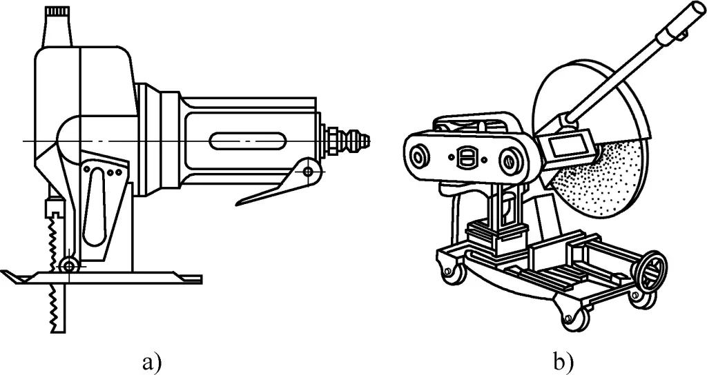
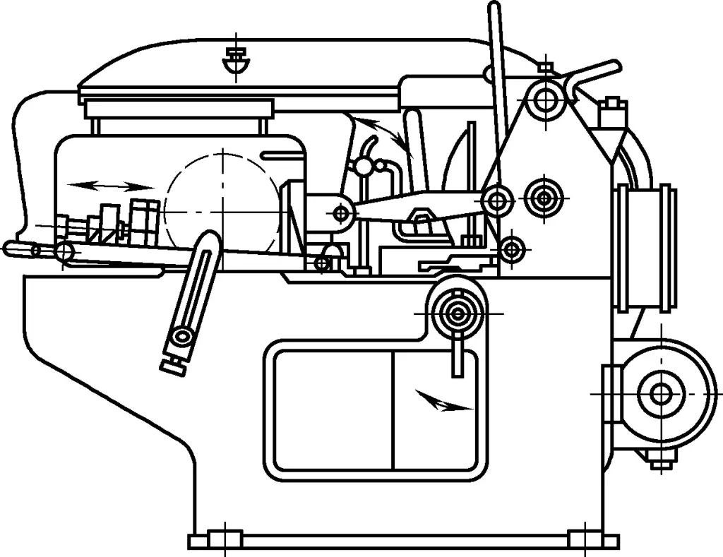
Among the common cutting methods mentioned above, the most commonly used in production are: shearing by a shearing machine, punching, oxyacetylene flame cutting, plasma cutting, laser cutting, and some cutting processes. Figures 1a and 1b show common hand-held pneumatic saws and grinding wheel cutting machines used for manual cutting. Figure 2 shows a common machine tool cutting bow saw machine.
II. Shearing
Shearing is a processing method in which plates, profiles, and rods are separated along predetermined straight or curved lines using specialized shearing equipment or tools, thereby obtaining various straight and curved outline blanks (sometimes also internal shapes). It is suitable for all kinds of materials except hardened steel and hard brittle materials (such as cast iron, ceramics, glass, cemented carbide, etc.).
1. Manual shearing techniques
Manual shearing is an important part of sheet metal skills, which includes feeding, removing excess material, etc. Almost all shapes of thin sheet parts can be sheared manually. Manual shearing is flexible and convenient, with almost no restrictions.
(1) Tools for manual shearing
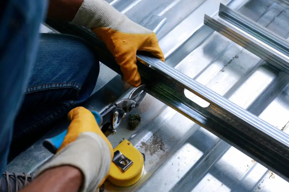
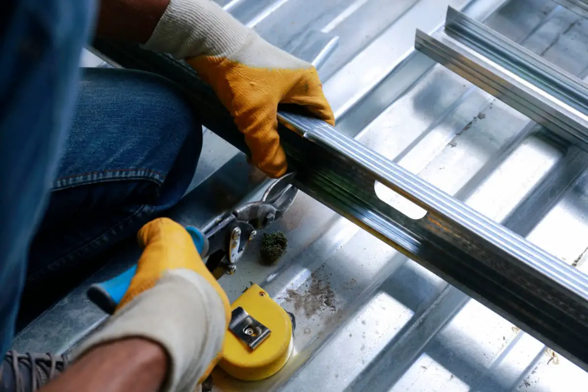
Tools for manual shearing include straight scissors, curved scissors, pneumatic straight scissors, and pneumatic punching shears (see Figure 3).

a) Straight scissors
b) Curved scissors
c) Pneumatic straight scissors
d) Pneumatic punching shears
Straight scissors are hand-operated shears with straight cutting edges, used for shearing straight outlines of plates, capable of shearing aluminum plates up to 1.5mm thick and steel plates up to 1mm thick. Curved scissors have cutting edges following a curve, used for shearing curved outlines of plates, capable of shearing aluminum plates up to 2mm thick and steel plates up to 0.8mm thick. The portable pneumatic shears are semi-mechanized hand shears, capable of shearing up to 2.5mm thickness.
(2) Manual shearing operations
1) Techniques for manual shearing
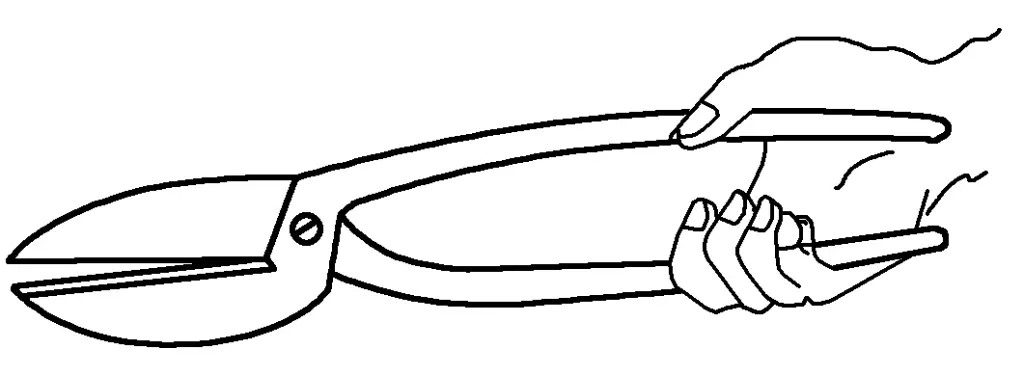
Generally, when manually shearing thin plates, it is customary to hold the scissors with the right hand and the material with the left hand. Figure 4 shows the correct method of holding the scissors; the scissors handle should not extend too long from the palm to facilitate exerting force on the handle, and the tail end should not be held inside the palm to avoid inconvenient gripping by the right hand.
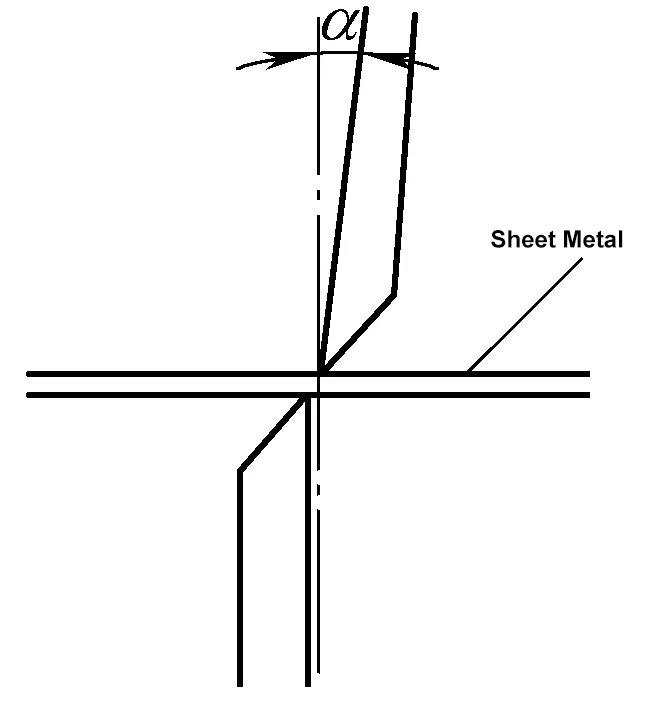
The left hand holds the material and feeds it in the shearing direction, aligning the upper blade with the shearing line (A tangent to a straight or curved line). During shearing, the upper blade should press the material tightly, and the blade angle should be adjusted to facilitate force, as shown in Figure 5.
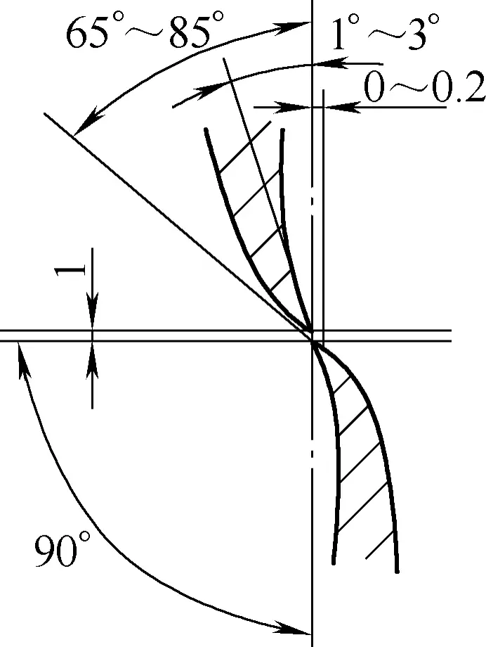
At the beginning of shearing, the two blades should only open up to 3/4 of the blade length. At the end of each cut, the blades should not completely close, leaving 1/4 of the blade length. In other words, the scissors should only partially open and close from the 1/4 position to the 3/4 position of the blade length, with each cut length being about 1/2 of the blade length, as shown in Figure 6.

a) Shearing starts
b) Shearing ends
During blade closure, continuous pressure should be applied along the cutting line, and the cutting edges should overlap. A gap of 0 to 0.2mm should be maintained between the two blades, with smaller values for thinner materials and larger values for thicker materials, as shown in Figure 7.
2) Method of Cutting Straight Lines
Figures 8a and 8b respectively show the correct and incorrect directions for cutting straight lines.
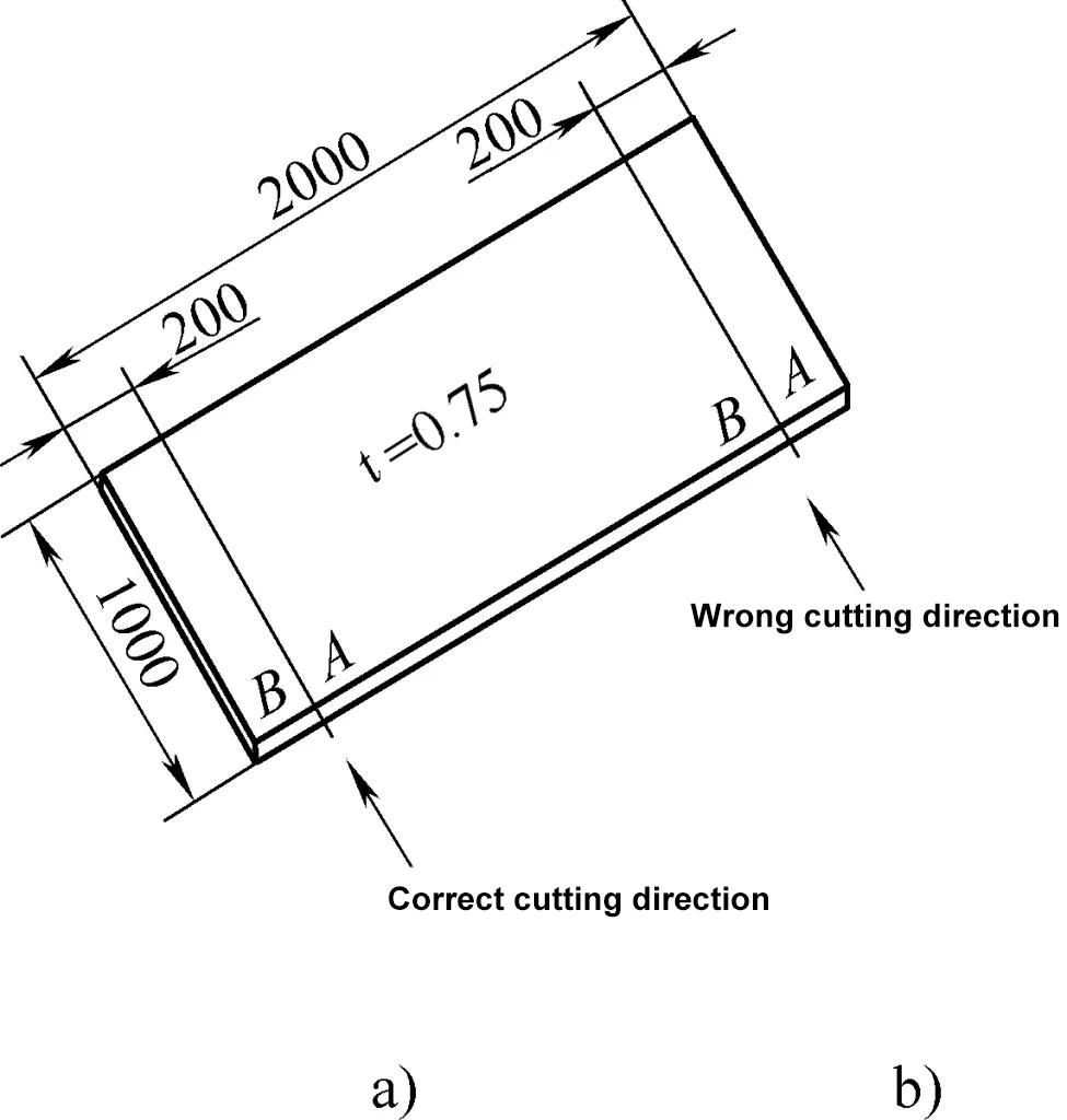
Figure 8a shows the correct direction because during the cutting process, the right hand holds the scissors body, the right foot steps on point A, the left hand holds point B. As the cut deepens, the left hand should lift up to assist in tearing at the cut point and make space for the lower scissors body. Since plate B is small, it can be easily lifted, making it the correct direction. On the other hand, in Figure 8b, the area and weight of point B are larger, making it difficult to lift the material and cut deep, thus it is the incorrect direction.
3) Method of Cutting Concave Corners and Angle Materials
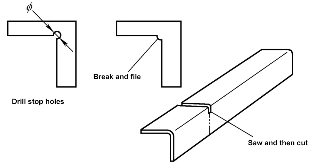
If the cutting line on the sheet metal forms a concave shape for the workpiece, a so-called concave corner, a crack-stop hole should be drilled at the intersection of the concave cutting line or a certain distance should be left uncut.
The purpose of drilling a crack-stop hole is to ensure that the end positions of the cutting lines on both sides fall on the crack-stop hole during cutting, or to leave a certain distance uncut so that the shear ends do not leave marks on the intersection of the workpiece, thus preventing stress concentration points.
Generally, a certain distance is left uncut at the intersection of the cutting lines, the connection is then broken by hand, and finally, a file is used to achieve the required shape and dimensions. For cutting diagonal-shaped parts, the root can be sawed first, and then the line can be cut with scissors as shown in Figure 9.
4) Method of Cutting Curves
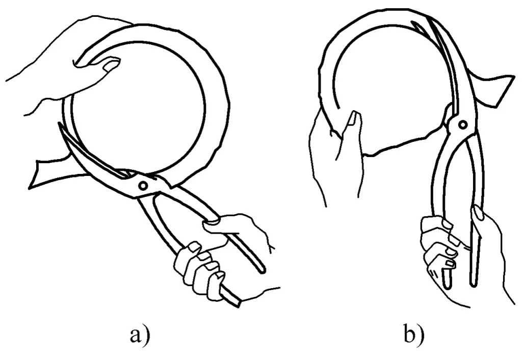
When the cutting line is a curve, the movement direction of the scissors should follow the curve without covering the cutting line to allow the operator to control the upper blade to stay tangent to the curve, as shown in Figure 10.
a) Clockwise Direction
b) Counterclockwise Direction
The method for cutting internal holes is to first create a process hole in the sheet metal, then gradually enlarge it along the cutting line using curved scissors in a spiral manner. For larger internal holes, a vibrating shear cut is preferable.
(3) Common Cutting Defects and Countermeasures
During the cutting operation of sheet metal, issues such as incomplete cutting, dimensional deviation, interrupted and non-straight cutting lines, cuts, and excessive burrs often occur. Below, we analyze these issues and provide corresponding solutions.
1) Incomplete Sheet Metal Cutting
The main reasons for incomplete cutting are:
① The gap between the upper and lower blades is too large. Different gaps are suitable for different thicknesses of sheet metal. A too-small gap can lead to blade wear and increased cutting force, while a too-large gap can cause material turning and incomplete cutting. The solution is to appropriately adjust the blade gap.
Figure 11 shows the methods for adjusting the gap. In Figure 11a, the method for narrowing the gap is to strike the edge of the rivet head, applying pressure to the convex washer of the scissors, causing some metal to move downward and reducing the blade gap. Do not use excessive force; usually, two or three light taps around the edge are sufficient.

In Figure 11b, the method for widening the gap is to place a fixed support under one blade and the handle (the closer to the pivot, the better), then strike the other blade (again, the closer to the pivot, the better). Do not use excessive force; usually, two or three light taps are sufficient.
If the convex washer has become flat (as shown in Figure 11c), no amount of hammering will adjust the gap. The solution in this case is to replace the rivet and the convex washer.
② Dull blade. The solution is to sharpen the blade.
③ The sheet metal is too thick, exceeding the range of hand cutting.
2) Dimensional Deviation in Cutting
The main reason for dimensional deviation is that the upper blade of the scissors is not aligned with the cutting line on the sheet metal. For straight cutting lines, the upper blade must align and press down along the line. For curved lines, the scissors should avoid covering the drawn line, and the upper blade should press the sheet metal and stay tangent to the line during cutting.
3) Interrupted and Non-Straight Cutting Lines
This is caused by:
① Loose connection between the scissors and the sheet metal during successive cuts. Continuously aligning the upper blade with the line can prevent this phenomenon.
② Long-term use causing the blades to bend, forming either an outward or inward curve. The solution is to straighten the blade or replace the scissors.
4) Cuts
The main reasons for cutting defects are:
① Not drilling crack-stop holes at the concave corner of the workpiece or letting the shear exceed the line, leaving uncut lines that become stress concentration points, eventually leading to various cracks. The only solution is to drill crack-stop holes or leave filing margins as required.
② Upper and lower blade gaps being too small, causing the entire blade to close and pinch the part during cutting. The solution is to adjust the blade gap and avoid fully closing the blades during cutting, leaving a quarter of the blade length and then making further cuts.
5) Excessive Burrs
The main reasons for excessive burrs are:
① Improper blade gap, whether too large or too small, causing large burrs. The solution is to adjust the gap and test cut a few times to find the optimal gap.
② Dull blades. Dull blades also cause excessive burrs, so regularly sharpening the blades improves product quality and processing efficiency.
(4) Precautions During Cutting Operations
During the cutting of sheet metal, pay attention to the following:
1) During manual cutting of thin sheet metal, the cutting faces of the blades must remain perpendicular to the sheet surface to maintain the blades in the most effective cutting position. Tilting the cutting face against the sheet surface is prohibited as it causes excessive burrs or even incomplete cuts or clamping of the workpiece between the pivot planes of the blades.
2) The cutting force applied by the blades on the workpiece should be continuous and smooth. When cutting thicker sheets, avoid hammering the back of the scissors to increase cutting force as it can damage the blade edges and convert curves into broken lines, affecting cut quality. Instead, extend the length of the scissors handles, e.g., by attaching a steel pipe, to increase cutting force.
2. Manual Chiseling Techniques
Like manual cutting, manual chiseling is an important sheet metal cutting skill, typically used for cutting sheets thicker than 3mm. Chiseling is completed using chisel tools and a sledgehammer.
Chiseling utilizes the cutting motion of the chisel blade to process the workpiece. The main feature of manual chiseling is that it is not limited by the working position or the shape of the parts, making the operation simple and flexible.
(1) Hand cutting tools
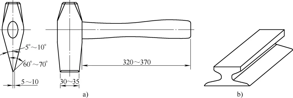
Commonly used hand cutting tools – kezi, divided into upper kezi and lower kezi, as shown in Figure 12. Among them, the lower kezi is usually made from waste scissors blades or processed from steel rails (see Figure 12b).
a) Dimensions of the upper kezi
b) Lower kezi
The blade part of the upper kezi has an asymmetric wedge shape. When cutting, the left side of the blade tip (see Figure 12a) is the part of the blank, and the right side is the waste part. Under the hammering force on the top, the blade tip of the kezi is squeezed into the part material along the kezi axis.
When the blade tip is wedged into most of the sheet metal, due to the significant squeezing force on the waste side of the asymmetric wedge-shaped blade, the sheet metal is torn along the blade tip line before the blade tip reaches the bottom of the sheet, separating the material.
As can be seen in Figure 12a, the cross-section of the kezi’s blade tip is different from that of general tools. The thick and wide blade tip ensures that the kezi does not deform or break under significant impact force and prevents the blade tip from embedding into hard and brittle materials, which could cause breakage or ejection and potentially cause injury. It primarily ensures the kezi’s function of separating materials (especially sheet metals).
(2) Hand cutting techniques
Before performing hand cutting on a workpiece, one should first familiarize themselves with the part drawing, understand the shape and dimensions of the workpiece. The chosen kezi should have a handle approximately 320-370mm in length, with a blade thickness of about 5-10mm, as shown in Figure 12a.
When performing hand cutting, the palm should face downwards, holding the kezi handle with the hand about 30-40mm away from the end of the kezi handle.
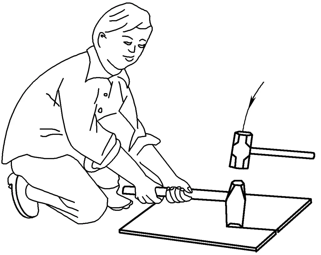
Cutting is done by two people working together. The person holding the kezi handle grips it tightly with both hands, making the kezi slightly slanted. After aligning the blade tip with the line on the sheet metal, they straighten the kezi, stand slightly upright, and focus on the blade tip. The other person then strikes the top of the kezi with a sledgehammer, ensuring the strikes are straight and accurate. When cutting marked steel plates on the platform, the person holding the kezi handle should squat, lean slightly forward, but keep their head upright and slightly back.
Leaning forward helps to hold the handle vertically stable, and keeping the head slightly back facilitates line observation, alignment, and avoiding accidental mishits from the hammer wielder. The left foot should step forward slightly, with the calf vertical to the ground, the thigh between the two arms, and the right foot should lean back slightly with the sole touching the ground, as shown in Figure 13.
During cutting, align the front end of the kezi blade with the working line, ensuring the kezi is not fully pressed into the sheet metal. Cutting should start from the edge of the sheet metal, with 1/3 of the kezi blade extending beyond the sheet edge and aligning with the lower kezi blade.
Once the edge of the sheet is cut, align the blade with the line to continue cutting downward. At this point, the rear end of the blade should tilt upwards by 10°-15° to facilitate line observation, focus hammering force on the front part of the kezi, and ensure continuous cutting of the sheet, as shown in Figure 14.
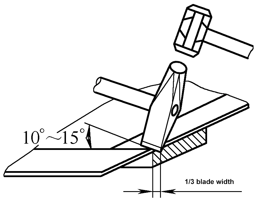
After hammering the top of the kezi, quickly tilt the rear end of the blade upward, have the front end of the blade slide backward along the cutting groove until the cutting line is completely finished. For nearing the end of the cut, hammer gently to avoid damaging the blade and the platform surface.
During the cutting process, due to the action of the blade tip side, the sheet metal will bend laterally and warp due to local extrusion, so flattened correction should be applied to the sheet after cutting.
After completing the cutting operation, promptly clean the work area.
(3) Hand cutting steps and methods
Despite the variety of sheet metal parts for cutting, the steps and methods for the cutting process are generally the same. The following detailed description of the hand cutting steps and methods is provided through an example.
The workpiece shown in Figure 15 is made from 4mm thick Q235A steel plate. The corners of the inner hole must not crack after cutting. The cutting steps and methods are as follows:
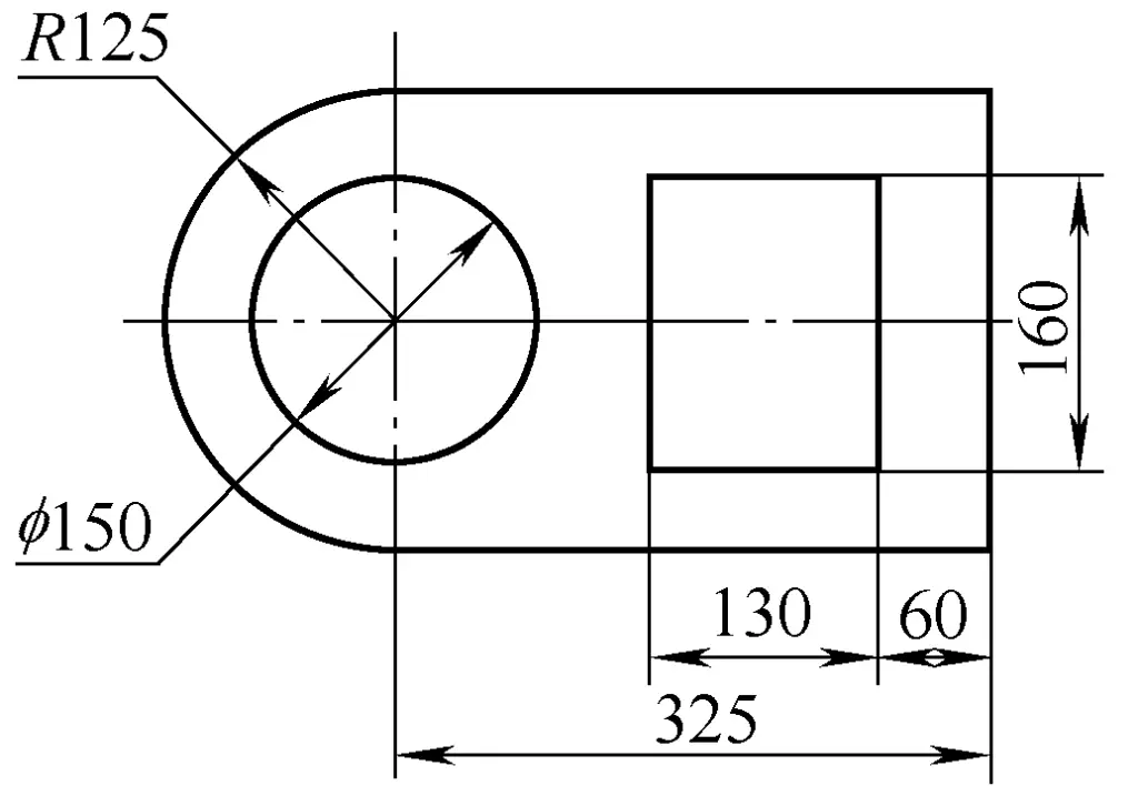
1) Marking
Prepare the sheet metal to be processed, use a template for marking or directly draw the pattern on the sheet metal at a 1:1 scale. To facilitate accurate alignment, determine the start cutting point first, then draw the starting line to the edge of the sheet metal to align with the lower kezi blade, as shown in Figure 16.
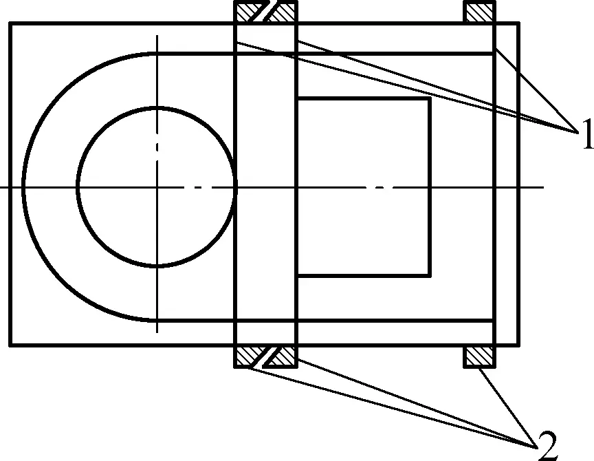
1—Starting line
2—Lower kezi blade
2) Determine cutting sequence
Analyze the workpiece pattern and determine the cutting sequence. Generally, the cutting sequence is: outer shape first, then inner holes; straight lines first, then curves; whole parts first, then sections. The cutting sequence for the workpiece shown in Figure 15 is arranged as shown in Figure 17.
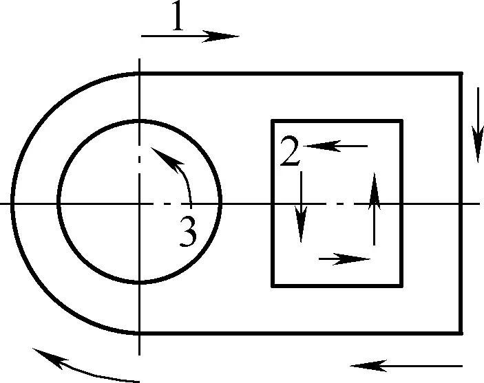
3) Cutting of Straight Sections
The cutting method for straight sections is:
① Start cutting.
Lay the sheet flat on the lower cutting edge, with the excess material protruding beyond the cutting edge, aligning it accurately with the cutting line so that it coincides with the lower edge. The position and angle of the cutter are as shown in Figure 14.
When starting the cut, the hammering force should be lighter to allow adjustment if the start cut is not accurate, preventing damage to the cutting edges from collision. Once the start cut is confirmed accurate, proceed with incrementally straight cutting along the lower cutter’s edge.
② Cutting.
During the cutting process, ensure the sheet’s cutting line aligns with the lower edge, maintaining a suitable angle on the upper cutter and keeping the two edges close. Failure to do so may result in incomplete cuts and bending deformation, as shown in Figure 18.
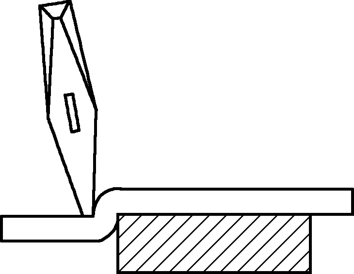
To improve quality during cutting, constantly correct any deviation and adjust the hammering force. This requires the operator to stay observant and closely coordinated, with the hammerer following the cutter holder’s commands.
4) Cutting of Curved Sections
The cutting method for curved sections is:
① Start cutting.
When cutting reaches a curved section, first cut off the excess material from the completed straight section to avoid interference. To minimize deformation, place the circular part on the lower edge and continuously rotate the workpiece, always using the end of the lower edge for cutting (see Figure 19).
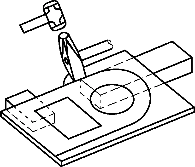
② Cutting.
When cutting curves, both the upper and lower edges are straight, so each cut creates only a segment. The essence of cutting curves is to cut out straight segments along the tangents of the curve, forming a polygon that approximates the curve. The shorter the segments, the closer to the curve.
The requirement for cutting curves is to keep each cut minimal and to frequently rotate the sheet; hammer strokes should be short and appropriate in force.
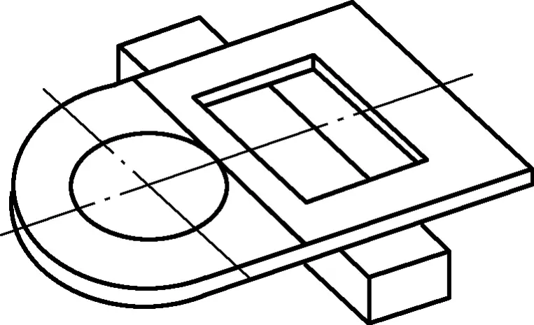
5) Cutting of Internal Square Holes
To ensure accurate opening for internal square holes, align as shown in Figure 20. For starting the cut, lightly hit the upper edge at the contact point with the sheet. Once the initial cut reaches 2-3 times the edge width, lay the upper edge flat and cut through completely (see Figure 21). Post-opening, the cutting method is the same as for straight sections.
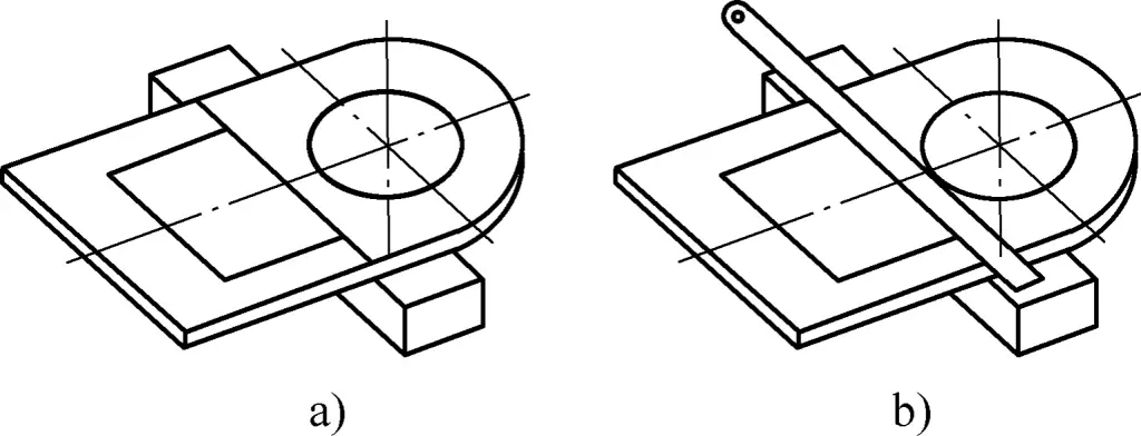
a) Align by Scribing Line
b) Align by Straight Edge over Line
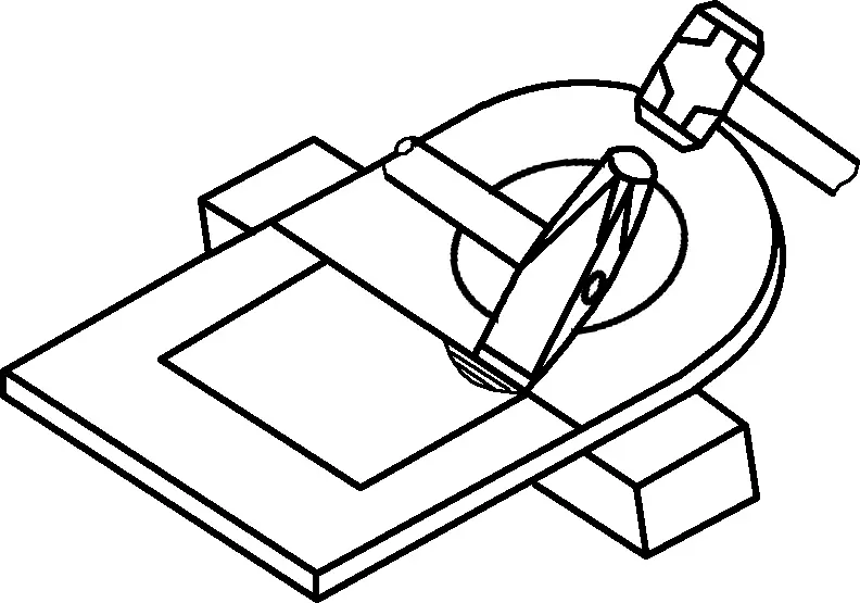
6) Cutting of Internal Circular Holes
For cutting internal circular holes, first choose the starting point. To facilitate start cutting, select a point that allows easy clamping and align the tangent at this point with the lower edge (see Figure 22). The cutting method is similar to the curved sections.
(4) Precautions for Manual Cutting Operations
During manual cutting, the cutting force is applied by a second person striking the top of the cutter with a sledgehammer. At the moment the hammer contacts the cutter, the hammer and cutter’s centerlines should be aligned and perpendicular to the sheet’s plane.
The handle holder’s posture must be correct, the grip stable, and the cutter alignment quick and accurate. The hammerer must strike straight and precisely, with both parties staying focused and coordinated.
Check the surroundings for pedestrians during cutting; start with low hammer height until accuracy and stability are ensured, then increase hammer height and force.
Operators should not wear gloves while cutting, especially the hammerer, as gloves reduce tactile feedback and may cause loss of grip, leading to accidents. Gloves must be worn for deburring, handling workpieces, and excess material to avoid injuries.
Frequently check the sledgehammer and cutter for tightness, ensuring the handle is secured with wedges to prevent loosening from prolonged use. Also, sharpen and remove any burrs from the cutter top to prevent injury from flying debris caused by hammering.
When the workpiece is about to break off, cut gently or use a hand hammer to avoid damaging the cutting edges or surface.
3. Mechanical Shearing Techniques
Mechanical shearing uses specialized equipment to cut and separate sheets, widely used in sheet metal cutting for its high efficiency and precision.
(1) Mechanical Shearing Equipment
Mechanical shearing equipment includes guillotine shears, vibratory shears, and rotary shears.
Guillotine shears are primarily used for cutting sheets into straight lines, operating on the principle of using linear blades on the upper and lower shearing edges.
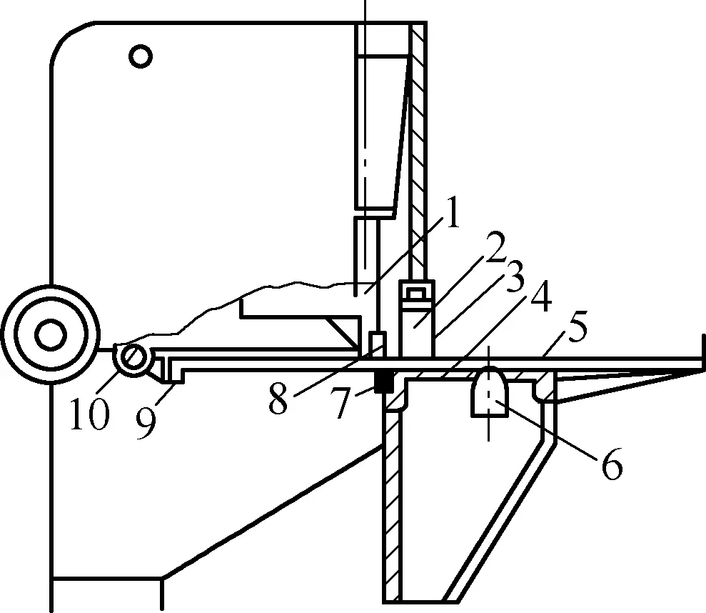
Figure 23 shows a schematic of the guillotine shear principle. The upper blade (8) is fixed to the blade holder (1), the lower blade (7) to the table (4). Balls (6) facilitate sheet movement, with the rear gauge (9) positioned by the positioning pin (10).
1—Blade Holder
2—Hydraulic Clamp Cylinder
3—Cover Plate
4—Table
5—Sheet
6—Balls
7—Lower Blade
8—Upper Blade
9—Rear Gauge
10—Positioning Pin
Hydraulic pressure cylinder 2 is used to press the sheet, preventing it from flipping during shearing. The protective plate 3 is a safety device to prevent work-related accidents. During operation, the crankshaft drives the shearer slider, cutting the material using the relative motion of the upper and lower shearing blades.
Shearing machines are classified into mechanical transmission shearing machines and hydraulic transmission shearing machines based on their transmission methods. Shearing machines with a plate thickness less than 10mm are mostly of mechanical transmission structure, while those with a plate thickness greater than 10mm mostly use hydraulic transmission structures.
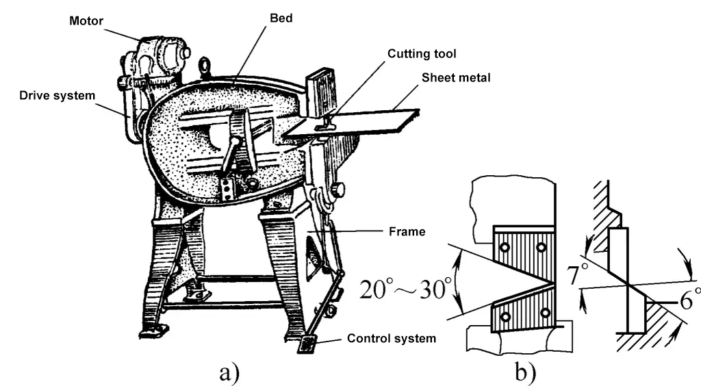
Vibration shearers are generally used for cutting based on lines or templates, commonly used for processing sheets less than 2mm thick. Its working principle involves generating high-speed reciprocating motion of the upper blade against the lower blade through mechanical transmission, cutting the sheet into small segments. Therefore, it can also be used for cutting curved outer and inner profiles with larger curvature radii. Its structure and working principle are illustrated in Figure 24.
a) Appearance
b) Upper and Lower Blades
The rolling shear machine can achieve straight-line shearing or shearing along a curve. Utilizing the characteristic that the rolling shear can cut circular or curved shapes, it can replace punch dies for cutting or trimming large stamping parts in small batch production, although the shearing quality and productivity are not high. The rolling shear machine uses a pair of circular blades rotating in opposite directions to shear the sheet.
Figure 25a shows the structure and working principle of the rolling shear machine, and Figures 25b, c, and d show several configurations of the circular blades.

a) Structure of Rolling Shear Machine
b) Straight Configuration of Circular Blades
c) Inclined Straight Configuration of Circular Blades
d) Inclined Configuration of Circular Blades
1—Motor
2, 3—Pulleys
4-9—Gears
10—Shaft
11—Operating Handle
12-15—Bevel Gears
16—Circular Blades
17—Drive Shaft
18—Base
(2) Basic Methods of Shearing with Shearing Machines
Shearing machines are divided into flat blade shearing and inclined blade shearing according to the different assembly of the upper and lower blades. Inclined blade shearing is more labor-saving than flat blade shearing and is mostly used for shearing wide and thin sheets. Figure 26a shows a schematic diagram of shearing using inclined blades.
Inclined blade shearing can significantly reduce the shearing force. In inclined blade shearing machines, the lower blade is horizontal, and the upper blade is inclined at a certain angle to the lower blade. Since the upper shear blade is inclined, the contact length between the blade and the material during shearing is much smaller than the width of the sheet, resulting in a larger stroke, smaller shear force, and smoother operation, making it suitable for shearing thin and wide sheets.
Generally, the inclination angle φ of the upper blade is between 1° and 6°. For sheet thicknesses of 3-10mm, φ=1°-3°; for thicknesses of 12-35mm, φ=3°-6°. γ is the rake angle, which helps reduce material rotation during shearing; α is the clearance angle, which helps reduce friction between the blade and the material. γ is generally 15°-20°, and α is generally 1.5°-3°.
Figure 26b shows a schematic diagram of flat blade shearing using a flat blade shearing machine. The characteristic of flat blade shearing is that it shears between parallel upper and lower blades. β is generally 0°-15°. This type of shearing machine has a small stroke but a large shearing force and is suitable for shearing thick and narrow sheets.

a) Inclined Blade Shearing
b) Flat Blade Shearing
(3) Operation Methods of Shearing Machines
Shearing machines use upper and lower straight-line blades to shear sheet blanks. To cut blanks into certain shapes and sizes, shearing machines are equipped with stopper devices, consisting of front, rear, side stoppers, and specialized angular stoppers.
The front, rear, and side stopper plates can be installed and fixed on the worktable or bed frame of the shearing machine, and can be adjusted in position front and back, left and right through an adjustment mechanism. Angular stopper plates are generally installed in the T-slots of the table surface and can be installed and secured in different positions on the table according to the shape of the sheet to be cut.
Although there are many digital display or CNC shearing machines that have achieved automatic positioning control and display on some stopper plates (such as the rear stopper plate), greatly facilitating the shearing of certain length blocks and strips, the shearing of more complex shapes still requires manual adjustment of various stopper plates.
For the cutting of complex-shaped pieces, the method of manual adjustment using templates is usually adopted. One important aspect of cutting operations is adjusting the positions of various stopper plates installed on the shearing machine to complete the shearing of strips and blocks of different widths and shapes, ensuring and controlling the quality. Shearing using stopper plates is illustrated in Figure 27.

a) Using Rear Stopper Plate
b) Using Front Stopper Plate
c) Using Angular and Rear Stopper Plates
d) Using Two Angular Stopper Plates
e) Using Rear and Angular Stopper Plates
f) Using Angular and Front Stopper Plates
1) Shearing of Strips of General Width
For shearing sheets of general width, positioning can be done using lines or the rear stopper plate, adjusting the position of the rear stopper plate with a screw. During shearing, the sheet is pressed tightly with a pressing plate, then the slider with the upper shear blade moves down, and the sheet is sheared when the upper and lower shear blades overlap. The sheared section usually does not require further processing to ensure the quality, as shown in Figure 27a.
2) Shearing of Wider Strips
For shearing wider strips, if the sheet is positioned using the rear stopper plate, the overhanging part will sag due to its weight. The positioning error increases as the ratio of the overhanging length to the sheet thickness (B/t) increases. Therefore, when the strip width exceeds 300-400mm, the front stopper plate should be used for positioning, as shown in Figure 27b. The position of the front stopper can be determined using general measuring tools or templates.
3) Shearing of Trapezoidal and Triangular Blocks
To shear trapezoidal and triangular blocks, the side stopper plate can be used in coordination with other stopper plates for positioning.
During installation, place the template on the table, align it with the lower blade, then adjust and secure the side stopper plate. Thereafter, adjust the rear stopper plate using the template, and use both the side and rear stopper plates for positioning during shearing, as shown in Figure 27c. Similarly, other methods for joint positioning using the side stopper plate and other stopper plates are illustrated in Figures 27d, e, and f.
4) Cut narrow material.
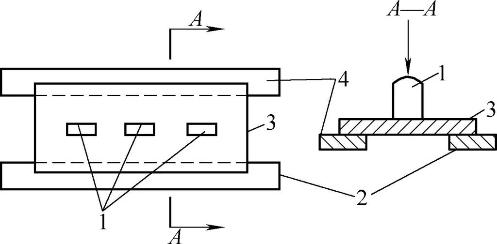
When the plate is too far from the pressing device and cannot be pressed down, for safe and smooth shearing, a padding board of the same thickness as the sheared plate can be added and pressed down by the pressing device for shearing. The pressing board can be thicker, as shown in Figure 28. For thin plates, no padding is required, and the pressing board can directly press down the plate.
1—Pressure device
2—Sheared steel plate
3—Pressing board
4—Padding board
4) Shearing machine operation steps and alignment methods
During the plate shearing operation, first strictly adhere to the safety operation procedures for shearing. Secondly, ensure the straightness and parallelism of the sheared surface of the plate and minimize the distortion of the material to achieve high-quality parts. Below, an example is given to illustrate the shearing operation steps and alignment methods in detail.
The workpiece shown in Figure 29 is made from a 10mm thick 25 steel plate. The tolerance of each dimension after shearing is ±1mm. The shearing operation steps and alignment methods using a gantry inclined shearing machine are as follows:
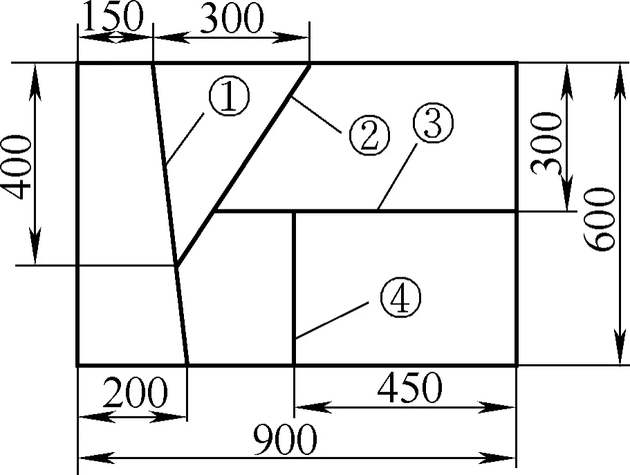
1) Shearing operation steps
Although the structure of the workpieces being sheared may vary greatly, the basic steps of the shearing operation are generally the same and can be performed as follows:
① Determine the number of people needed for shearing.
For larger plates, it is not advisable for one person to operate alone during shearing. Two to three people should be coordinated to perform the task with one person designated as the leader, and all actions should be consistent and follow the leader’s commands.
② Determine the shearing sequence.
Workpieces often have multiple shearing lines. When using a gantry inclined shearing machine, the shearing sequence must ensure that each shearing separates the plate into two parts. Figure 29 shows the shearing sequence for the workpiece, following the sequence of the shearing lines.
③ Analyze and determine the alignment method for the workpiece shearing.
There are multiple methods for aligning the workpiece on a gantry inclined shearing machine. These methods should be flexibly applied based on the analysis of the workpiece structure. For this workpiece, the alignment method used is:
- Shearing line ① is aligned using direct visual alignment or shadow alignment.
- Shearing line ② is aligned using an angle stopper board.
- Shearing line ③ is aligned using the back stopper board.
- Shearing line ④ is aligned using the front stopper board.
④ Based on the nature and thickness of the shearing material, inspect and adjust the gap of the shear blades. If the shearing machine comes with a shear blade gap adjustment data table, adjust the gap according to the data. Alternatively, refer to Table 2 to determine the shear blade gap.
Table 2: Reasonable gap ranges for shearing machines (Unit: mm)
| Material type | Gap (t%) |
| Electromagnetic pure iron Mild steel (low carbon steel) Hard steel (medium carbon steel or high strength steel) Electrical silicon steel Stainless steel Low alloy steel Hard aluminum, brass Anti-rust aluminum | 6~9 6~9 8~12 7~11 7~13 6~10 6~10 5~8 |
Note: In the table, t represents the thickness of the sheared plate.
⑤ After checking and adjusting the shear blade gap, run the machine in an unloaded state to confirm it is working properly before loading material. Before loading, clean the surface of the plate and check that the shearing lines are clear and accurate.
⑥ Perform the shearing. Follow the determined alignment methods and shearing steps.
⑦ Quality inspection. Measure the dimensions of all parts of the sheared workpiece to ensure they meet the design requirements and check the quality of the sheared edges.
2) Operation of shearing alignment method
Perform shearing operations on the workpiece shown in Figure 28 using the determined alignment methods.
Shearing line ①.
Place the plate on the shearing machine table, push it into the shear opening, visually align the ends of the shearing line with the lower shear blade edge, as shown in Figure 30. Then, remove your hands from the shear opening to outside the pressing plate, and press or step on the switch to shear the plate.
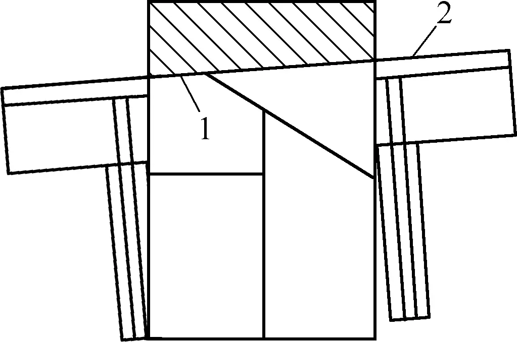
1—Shearing line ①
2—Lower shear blade edge
Shearing line ②.
Adjust and fix the angle positioning stopper board, use the stopper board as the positioning reference, place the plate properly on the shearing machine, and shear along shearing line ②, as shown in Figure 31.
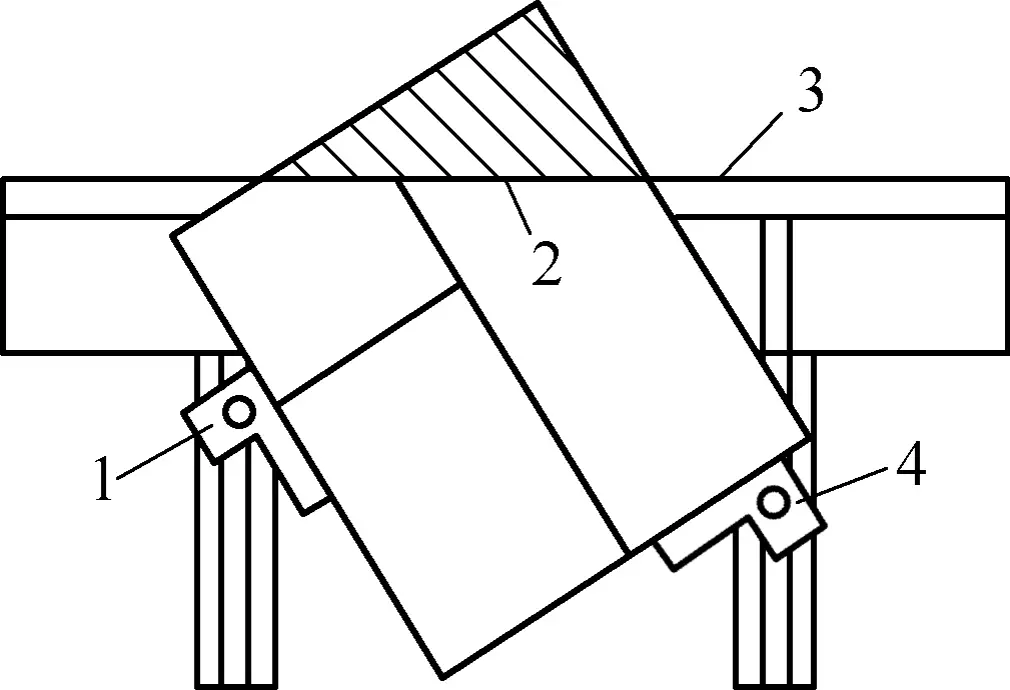
1, 4—Angle stopper board
2—Cutting Line ②
3—Lower Blade Edge
Cutting Line ③.
When positioning the cutting line ③ with the back gauge, the position of the back gauge can be determined in two ways: The first method is direct measurement with a steel ruler, ensuring that the distance from the upper and lower blade edges to the back gauge surface is equal to the width of the material to be cut. After fixing the back gauge, re-measure to ensure accurate positioning.
The second method is the template positioning method. By placing a template of the same width as the material to be cut between the lower blade edge and the back gauge, the position of the back gauge can be determined. Once the back gauge position is set, cutting line ③ can be positioned and cut, as shown in Figure 32.
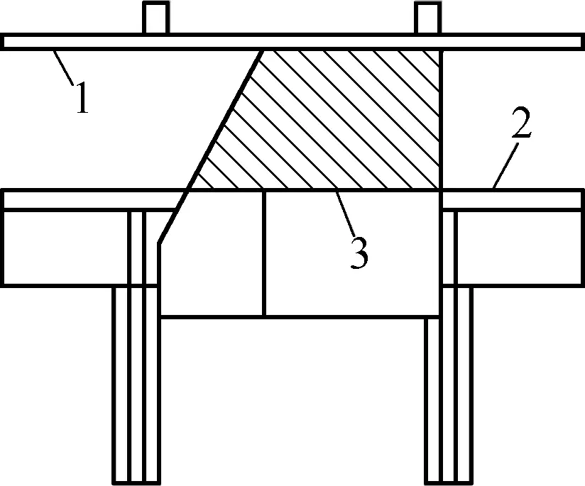
1—Back Gauge
2—Lower Blade Edge
3—Cutting Line ③
Cutting Line ④.
When positioning the cutting line ④ with the front gauge, the method for determining the front gauge position is the same as for the back gauge. The scenario for front gauge positioning and cutting is shown in Figure 33.
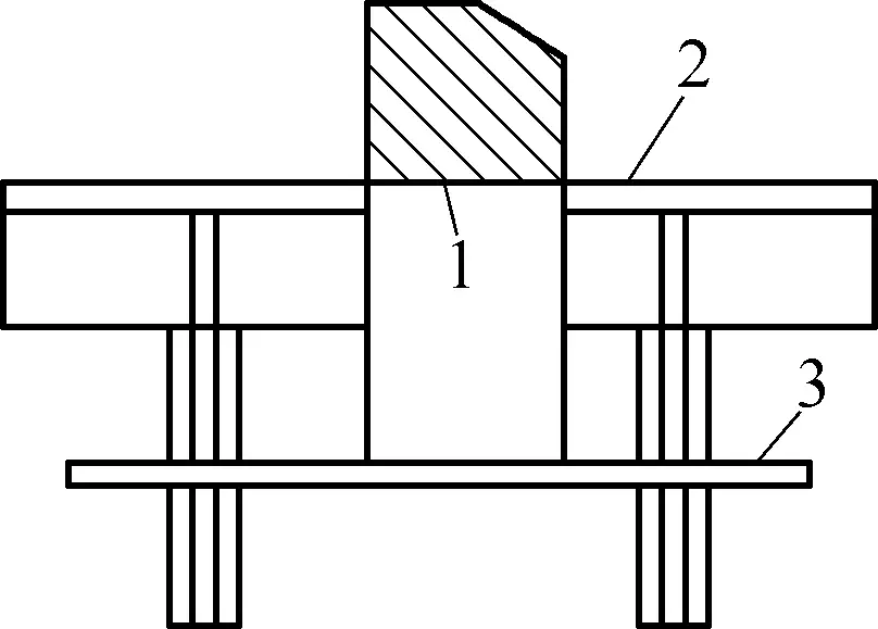
1—Cutting Line ④
2—Lower Blade Edge
3—Back Gauge
(5) Operational Precautions for Shearing Machines
Comparatively speaking, the operation of blanking processing has a lower technical content, but shearing blanking with a shearing machine is prone to operational accidents. To ensure the quality of blanking workpieces and the safety of blanking operations, the following precautions should be observed during the blanking process:
1) Before startup, carefully check whether the operating system, clutch, and brake of the shearing machine are in reliable and effective condition, and ensure that the safety devices are complete and reliable. If any abnormalities are found, take necessary measures immediately. It is forbidden to operate equipment with faults. Ensure that there is no significant knocking sound of pins and keys in the rigid clutch during operation.
2) The motor should not start under load. The clutch should be disengaged before starting the machine. Conduct a no-load trial run before official operation to check for any malfunction of the pull rod and any loosening of screws, and confirm that all components are normal before proceeding with official operation.
3) Concentrate during shearing operations. If multiple people are operating, the cutting switch must be controlled by a designated person. It is strictly forbidden to extend hands into the cutting area. Focus during feeding, particularly to ensure the safety of the operator’s fingers. When a sheet material is cut to the end, do not use fingers to push the material from underneath.
4) The blades and edges must be sharp. When cutting thin sheets, the blades must fit tightly. Keep the upper and lower blades parallel, do not use dull blades, and check whether the cutting edges are smooth. After adjusting the blades, conduct a manual test and a no-load test.
5) When cutting small pieces of material, use a pressure pad to prevent improper pressing and accidents.
6) Do not place other items or unrelated objects on the workbench. Any adjustments and cleaning must be performed with the machine stopped.
7) It is strictly forbidden for two people to shear two different sheets on the same shearing machine simultaneously. Do not step on the foot pedal or pull the air hook before the workpiece is aligned. Never place your head or hands under the blade at any time or under any circumstances.
8) Keep the workspace around the site tidy, ensuring unobstructed vertical lifting of workpieces or sheets.
9) It is prohibited to use the shearing machine to process overlong or over-thick workpieces. Do not use the shearing machine to cut quenched steel, high-speed steel, alloy tool steel, cast iron, and brittle materials.
The main specifications for calibrating the shearing machine are t×B (t is the maximum allowable thickness of the material to be sheared, and B is the maximum allowable width of the sheet). The shearing machine should not be used to process workpieces that exceed the maximum allowable shearing width B and thickness t.
When shearing high-strength materials (such as spring steel and high-alloy steel plates), verify the maximum permissible shearing thickness tmax. This is because the design of the shearing machine generally considers medium-hardness materials (tensile strength around 500 MPa and steel types 25-30). Therefore, if the tensile strength σb of the material to be sheared is greater than 500 MPa, the maximum permissible shearing thickness tmax should be calculated by the following formula:
tmax=√(500t/σb)
In the formula
- t – Maximum allowable shearing thickness (mm) of the calibrated shearing machine;
- σb – Tensile strength (MPa) of the material to be sheared;
- tmax – Calculated maximum permissible shearing thickness (mm) of the shearing machine.
Using this formula, if the calculated maximum permissible shearing thickness is less than the thickness of the material to be sheared, the shearing machine cannot be used. Table 3 lists the technical specifications of the shearing machine.
Table 3 Technical Specifications of Shearing Machine
| Parameter | Model | ||||
| Q11-1×1000 | QY11-4×2000 | Q11-4×2500 | Q11-12×2000 | Q11Y-16×2500 | |
| Sheet Thickness (mm) | 1 | 4 | 4 | 12 | 16 |
| Sheet Width (mm) | 1000 | 2000 | 2500 | 2000 | 2500 |
| Shearing Angle | 1° | 2° | 1°30′ | 2° | 1°~4° |
| Stroke Count (times/min) | 65 | 22 | 45 | 30 | 8~12 |
| Back Gauge Distance | 500 | 25~500 | 650 | 750 | 900 |
| Power (kW) | 0.6 | 6.5 | 7.5 | 13 | 22 |
| Structural Form | Mechanical Underdrive | Hydraulic Underdrive | Mechanical Drive | Hydraulic Drive | |
10) When cutting long plates, auxiliary supports should be available; when cutting large and heavy plates, to facilitate feeding and reduce the friction on the surface of the cut material, rolling supports should be available (i.e., supports with steel balls to hold the material, structure as shown in Fig. 34). In addition, a lifting device should be used to lift the plates, along with sufficient auxiliary workers, and coordination with auxiliary workers should be ensured.
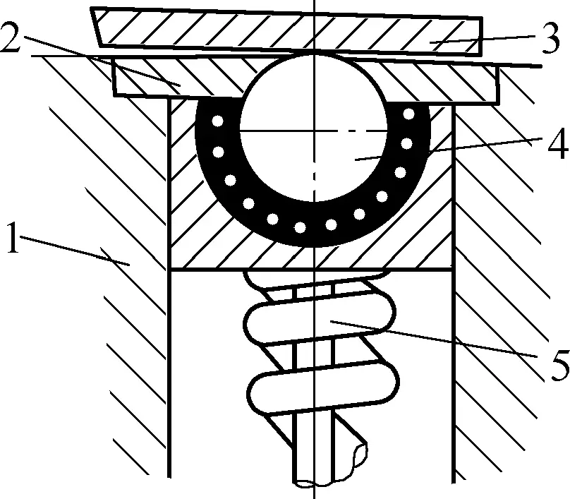
1—Support
2—Press cover
3—Cut plate
4—Steel ball
5—Spring
III. Blanking
Blanking is a stamping process that uses a die under the pressure of a press to separate a part of the sheet or strip material placed between the punch and die edges, thereby obtaining the desired shape and size of flat blanks or parts.
The method of cutting the required shape from sheet material is called blanking. For mass production of parts, blanking can improve production efficiency and product quality.
During blanking, the material is placed between the punch and die, and under the action of external force, the punch and die generate a shearing force, separating the material under the action of the shearing force (see Fig. 35). The basic principle of blanking is the same as that of shearing, except that the straight cutting edge in shearing is changed to a closed circular or other form of cutting edge.
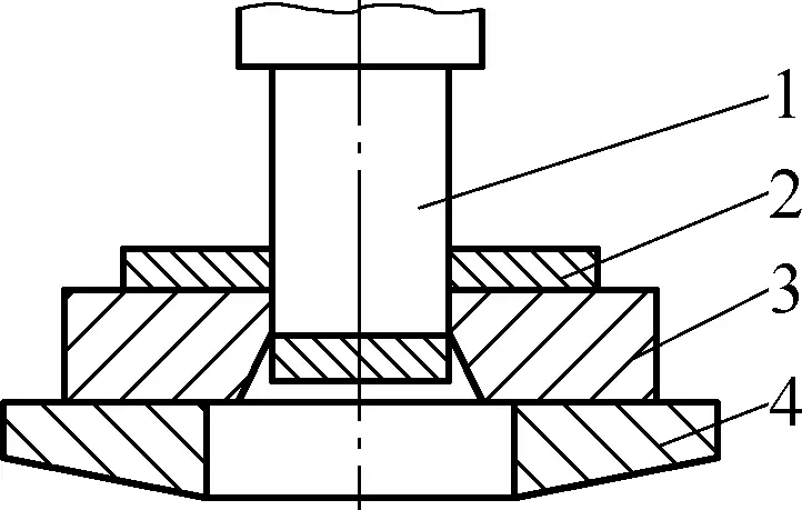
1—Punch
2—Sheet material
3—Die
4—Press table
1. Production elements of blanking processing
According to the principle of blanking processing, blanking is mainly completed by placing the sheet material on a die mounted on a press. Therefore, the sheet material, blanking equipment, and blanking die constitute the basic production elements of blanking processing.
(1) Raw materials for blanking
The main raw materials for blanking are metal sheet materials, and some profiles (pipes) and non-metal materials can also be processed. Common materials for blanking are shown in Fig. 36.
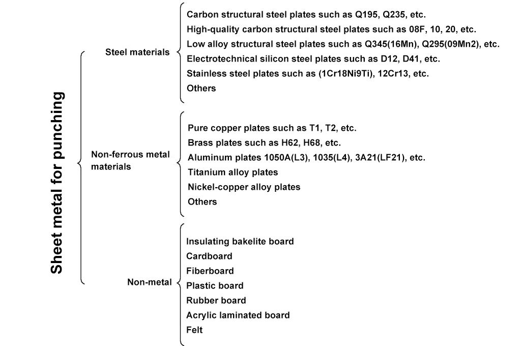
Note: The numbers in parentheses are the old standard grades.
Although a wide range of raw materials are used for blanking, not all materials are suitable for blanking. The raw materials used for blanking must have good stamping performance, good usability, and good surface quality to suit the characteristics of the blanking process.
(2) Blanking equipment
The main equipment for blanking are crank presses, which are forging machines driven by crank mechanisms. Presses are classified by nominal pressure into large, medium, and small sizes. Small presses have a nominal pressure of less than 1000 kN, medium presses have a nominal pressure of 1000 to 3000 kN, and large presses have a nominal pressure of over 3000 kN.
According to structural form, presses can be divided into open and closed presses. Open presses have a C-shaped frame that allows the operator to approach the worktable from the front, left, and right, making them easy to operate. However, due to the limited rigidity of the frame, open presses are only suitable for small and medium-sized presses. Closed presses have a completely enclosed frame and greater rigidity, making them suitable for general-purpose medium and large presses and high-precision light presses.
Additionally, crank presses can be divided into crankshaft presses and eccentric presses based on the structure of their main working shafts.
1) Crankshaft presses
Crankshaft presses use a crank mechanism formed by a crankshaft as the main working shaft to complete force magnification and motion transformation. The structure and working principle of the JB23-63 crank open inclinable press are explained below (see Fig. 37).
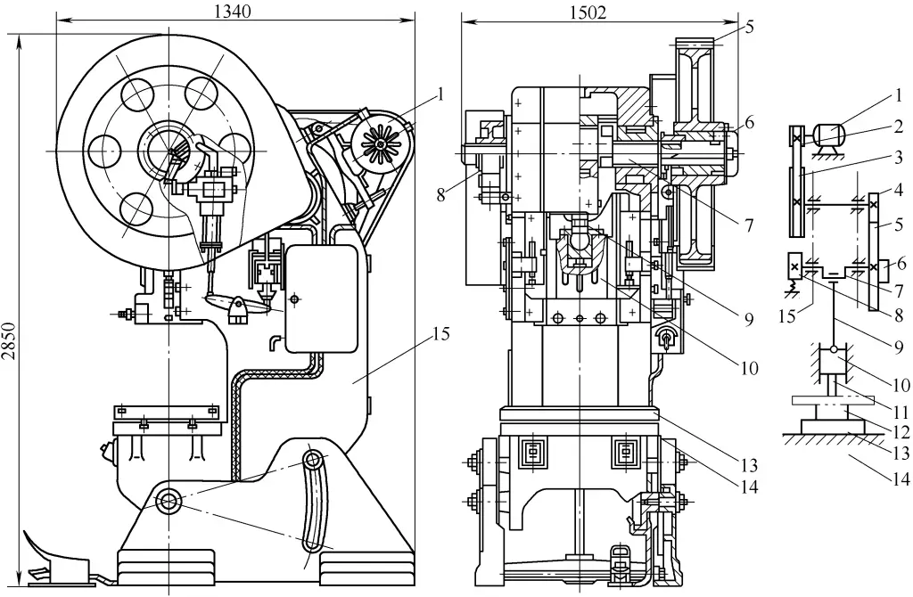
1—Motor
2—Small pulley
3—Large Pulley
4—Small Gear
5—Large Gear
6—Clutch
7—Crankshaft
8—Brake
9—Connecting Rod
10—Slider
11—Upper Die
12—Lower Die
13—Backing Plate
14—Worktable
15—Machine Body
When the press operates, the motor 1 transmits motion to the large pulley 3 through the V-belt, and then through the small gear 4 and the large gear 5 to the crankshaft 7. The upper end of the connecting rod 9 is installed on the crankshaft, and the lower end is connected to the slider 10, converting the rotational motion of the crankshaft into the reciprocating linear motion of the slider. The highest position of the slider 10’s motion is called the top dead center, and the lowest position is called the bottom dead center.
Due to the requirements of the production process, the slider sometimes moves and sometimes stops, so a clutch 6 and a brake 8 are installed. Because the press operates for a very short time during each working cycle, and most of the time it runs without load, a flywheel is installed to make the load on the motor more uniform and effectively utilize the equipment’s energy. The large pulley also serves as the flywheel.
When the press is working, the upper die 11 of the used mold is installed on the slider, and the lower die 12 is directly installed on the worktable 14, or a backing plate 13 is added to the worktable to achieve the appropriate closing height. At this time, placing the material between the upper and lower dies can perform punching or other forming processes to produce workpieces.
As can be seen from Figure 37, the stroke of the slider 10 (i.e., the distance from the top dead center to the bottom dead center of the slider) is equal to twice the eccentricity of the crankshaft 7, characterized by a large stroke of the press that cannot be adjusted.
However, because the crankshaft is supported by two or more symmetrical bearings on the press, the load on the press is more uniform, so large-stroke and large-tonnage presses can be manufactured.
2) Eccentric Press
The eccentric press uses a crank mechanism formed by using an eccentric main shaft as the working main shaft to complete force amplification and change the form of motion. As shown in Figure 38, the stroke of the press slider can be adjusted by adjusting the position of the eccentric sleeve 5 in the press.
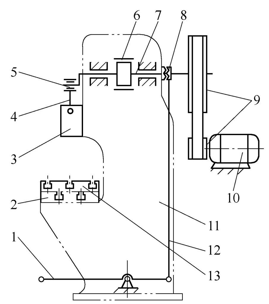
1—Pedal
2—Worktable
3—Slider
4—Connecting Rod
5—Eccentric Sleeve
6—Brake
7—Eccentric Main Shaft
8—Clutch
9—Pulley
10—Motor
11—Bed
12—Control Lever
13—Worktable Backing Plate
This type of press is characterized by a small but adjustable stroke, so it can be used for punching processes in dies that do not require a large stroke, such as guide plate dies.
(3) Punching Dies
The commonly used punching dies for sheet metal parts are single-process dies, which complete one punching process (punching or blanking) per stroke of the press. According to different punching processes, commonly used punching dies for sheet metal parts include punching dies, blanking dies, etc. According to different guiding methods, they can be divided into open punching dies, die-set guided punching dies, and guide plate punching dies, etc.
1) Punching Die
As shown in Figure 39b, a structural diagram of the punching die used for processing the holes in the part shown in Figure 39a.
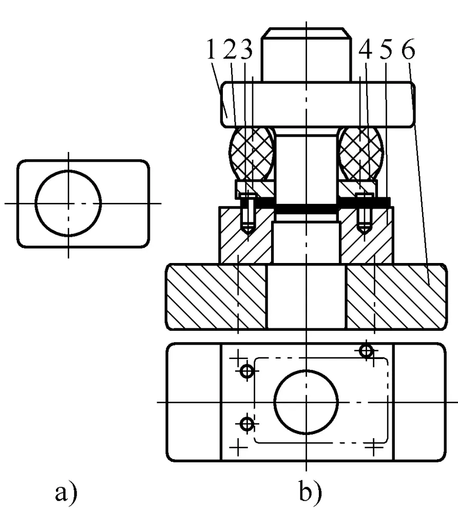
a) Part Structural Diagram
b) Die Structural Diagram
1—Upper Die
2—Rubber Elastic Body
3—Positioning Pin
4—Stripper Plate
5—Female Die
6—Lower Die Plate
This die is a simple open-type punching die without guidance. The sheared blanks are positioned by three positioning pins installed on the female die 5. The upper die 1 and the female die 5 punch out round holes together, and the stripper plate 4, powered by the compressed rubber elastic body 2, pushes out the parts clamped on the upper die punch.
This type of die has a simple structure, is easy to manufacture and low cost, but the die clearance adjustment is troublesome, the quality of the punched parts is poor, and the operation is not very safe. It is mainly used for punching parts with low accuracy requirements, simple shapes, and small batches.
2) Blanking Die
Blanking die is a single-process die that completes the blanking process. The blanking die requires reasonable clearance between the punch and die, accurate positioning of the strip material in the die, smooth falling of the blanked parts, flatness of the blanked parts, and good quality of the sheared surface.
Figure 40 shows a blanking die with sliding guide posts. The blanking die guided by a guide post die set uses guide posts and guide sleeves as guiding components that fit together. During operation, they always fit with a H6/h5 or H7/h6 clearance, ensuring that the working parts (punch and die) of the die are correctly positioned and ensuring the quality of the blanked parts.
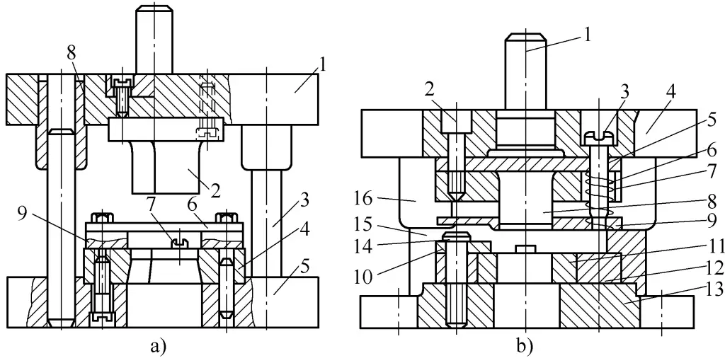
a) Blanking die with fixed stripper plate
b) Blanking die with elastic stripper plate
a) In the figure:
1—Upper die holder
2—Punch
3—Guide post
4—Die
5—Lower die holder
6—Stripper plate
7—Positioning pin
8—Guide sleeve
9—Guide ruler
b) In the figure:
1—Die shank
2—Inner hexagon socket head cap screw
3—Stripping screw
4—Upper die holder
5—Backing plate
6—Punch fixing plate
7—Spring
8—Punch
9—Stripper plate
10—Positioning plate
11—Die
12—Die insert
13—Lower die holder
14—Screw
15—Guide post
16—Guide sleeve
As shown in Figure 40a, a blanking die with a fixed stripper plate is used mainly for stamping thick (t>0.5mm) and rigid parts. During the operation of the die, the strip material is fed by the left and right guide rulers 9 and positioned directly by the positioning pin 7 to ensure that the sheet material has the correct position on the die.
When the press slide descends, the punch 2 and die 4 gradually contact the sheet material and cut it. As the slide ascends, the punch 2 also ascends, and the stripper plate 6 mounted on the guide rulers 9 scrapes off the strip material adhering to the punch 2. The blanked parts fall directly through the scrap hole under the lower die holder.
As shown in Figure 40b, a blanking die with an elastic stripper plate is used primarily for stamping thin (t<0.5mm) parts and can maintain good flatness of the parts. The stripping system consists of stripper plate 9, stripping screw 3, and spring 7. When the punch 8 descends with the press to punch the sheet material, the stripper plate 9 also descends and presses the sheet material, while the spring 7 compresses.
After punching, the product falls directly through the scrap hole in the lower die holder, while the waste ascends with the strip material tightly wrapped around the punch 8. The spring 7, through the resetting of the stripper plate 9, strips the waste off. The elastic stripping system can use springs as elastic elements or rubber elastomers, rubber, etc.
The die guided by the die set has high guiding accuracy, long die life, and is suitable for mass production of parts.
As shown in Figure 41c, a guide plate-type blanking die is used to process the round parts shown in Figure 41a. Figure 41b shows the layout of the parts.
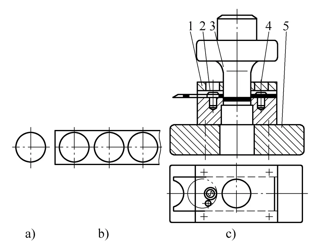
a) Schematic diagram of part structure
b) Schematic diagram of part layout
c) Schematic diagram of die structure
1—Guide plate
2—Cylindrical pin
3—Upper die
4—Die
5—Lower template
This type of die has higher precision than unguided dies, complex manufacturing, but is safer to use, easy to install, and generally used for simple shapes and small sizes of single-process blanking dies with sheet thickness t>0.5mm. It requires small press stroke to ensure that the punch does not separate from the guide plate during operation.
For complex shapes and larger parts, this type of structure is not suitable, and it is better to use a die structure with guide posts and guide sleeves for guiding.
When the guide plate punch works, it guides through the small gap between the working part of the upper die 3 and the guide plate 1. For materials less than 0.8mm, use an H6/h5 fit; for materials greater than 3mm, use an H8/h7 fit.
The guide plate also acts as a stripper. During punching, ensure the puncher does not leave the guide plate to maintain the guide accuracy, especially for multiple or small punchers. If the puncher leaves and re-enters the guide plate, the sharp edge of the puncher can be easily damaged and the guide hole on the guide plate can be easily gnawed, affecting the life of the puncher and the guide accuracy between the puncher and the guide plate.
3) Structure composition of the punching die
Although there are many structural forms of punching dies, regardless of the form, their structure consists of the following parts.
① Punch and die.
These are the parts that directly shear the material and are the core parts of the punching die. Usually, the punch is fixed on the upper template, and the die is fixed on the lower template.
② Positioning device.
Its function is to ensure the correct position of the punched part in the die, usually consisting of positioning parts such as a guide plate or positioning pin, fixed on the lower die holder to control the feed direction and feed amount of the strip.
③ Stripping device.
Its function is to separate the sheet material or the punched part from the die, usually consisting of parts such as a rigid or elastic stripping plate. When punching is completed and the punch moves upwards, the strip on the punch is blocked and falls by the stripping plate. In addition, the downward expanded taper hole on the die helps to eject the punched material from the die.
④ Guiding device.
Its function is to ensure the correct relative position between the upper and lower parts of the die, usually consisting of guide sleeves and guide pillars, guide plates, etc. During operation, the guide ensures the correct fit between the punch and the die.
⑤ Clamping and fixing device.
Its function is to ensure the firm and reliable connection between the die and the press, as well as between parts of the die, usually consisting of parts such as the upper template, lower template, die shank, pressure plate, bolts, and screws. These parts combine and assemble various parts of the die and fix them on the press.
⑥ Pressing device.
Its function is to prevent wrinkling of the punched part and improve the quality of the punching section, usually consisting of an elastic hold-down ring, etc.
2. Determination of main parameters of punching
To ensure the quality of punched parts, the following process parameters should be determined when formulating punching processes and designing punch dies.
(1) Determination of layout
The arrangement method of punched parts on the strip is called layout. The basic principles of layout are to improve material utilization rate, facilitate safe and easy operation for personnel with low labor intensity, and simplify die structure. The main task of layout work is to design the layout diagram, for which the values of overlap, step distance, etc. must be determined.
1) Determination of overlap value
During layout, a certain process allowance is left between punched parts and between punched parts and the strip’s sides, called overlap.
The purpose of setting overlap is to compensate for cutting errors of the strip, feeding step errors, and feeding skew errors due to gaps between the strip and the guide plate during punching. Additionally, it ensures that the cutting edges of the punch and die can bear forces on both sides, providing certain rigidity to the strip during continuous feeding, avoiding defective parts such as missing corners, and enhancing the die’s life and the quality of the part section.
Excessive overlap wastes material, while too little overlap does not serve the intended purpose. Insufficient overlap can easily be squeezed into the die, increasing cutting edge wear and affecting die life.
Overlap value is usually determined by experience. Table 4 shows the overlap values for low-carbon steel sheets. Once the overlap value is determined, the strip width for shearing can be decided based on the layout method.
Table 4 Overlap values a and a1 for low-carbon steel sheets (unit: mm)
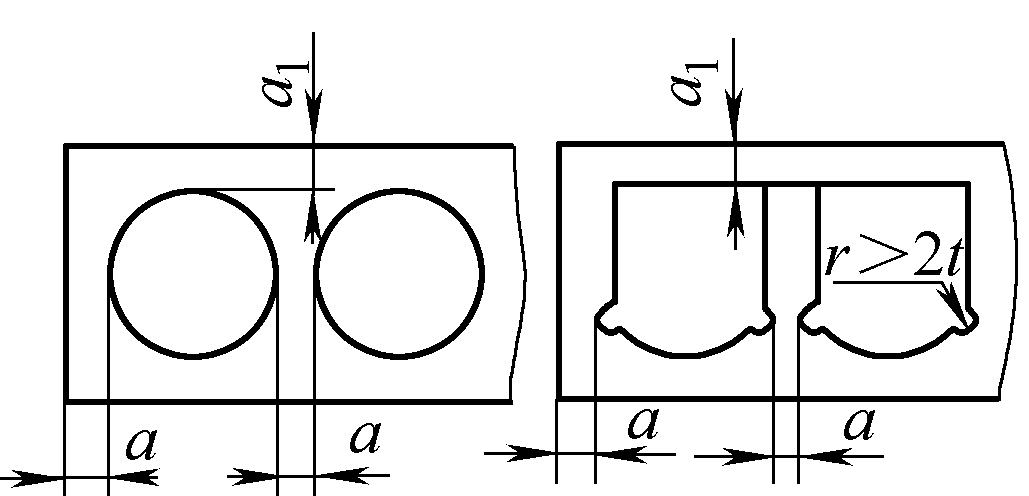
Note:
For other materials, multiply the values in the table by the following coefficients: medium carbon steel 0.9; high carbon steel 0.8; hard brass 1~1.1; hard aluminum 1~1.2; soft brass, pure copper 1.2; aluminum 1.3~1.4; non-metals (leather, paper, fiberboard, etc.) 1.5~2.
2) Determination of step distance
The distance the strip moves forward each time on the die is called the feed step distance A. The step distance is the basis for determining the position of the block pin.
The calculation of the step distance is related to the layout method. The size of the step distance is the distance between the corresponding points of two corresponding punched parts on the strip, as shown in Figure 42.
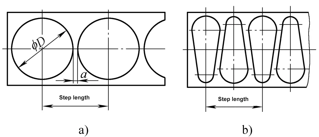
a) Layout diagram of circular parts
b) Layout diagram of irregularly shaped parts
(2) Calculation of punching force
Punching force is the main basis for selecting an appropriate press and is also a necessary data for designing the die and checking the strength of the die. For normal flat-edged punching, the calculation formula for punching force is:
In the formula
F=Ltσb
- F – Punching force (N);
- L – Perimeter of the punched part (mm);
- t – Thickness of the sheet (mm);
- σb – tensile strength of the material (MPa).
In the blanking process, besides the blanking force, there are also stripping force, pushing force, and ejecting force. The force to remove the material clinging to the punch after blanking is called stripping force, denoted as Fstrip; the force to push or eject the material stuck in the die is called pushing force and ejecting force, denoted as Fpush and Feject respectively. The magnitude of these forces is generally the blanking force F multiplied by a factor (0.04 to 0.12). The specific selection of the factor can be referenced from related stamping calculation materials.
The total blanking pressure required during blanking is the sum of the blanking force, stripping force, pushing force, and ejecting force. When choosing a press, it should be considered whether all these forces need to be taken into account, depending on the structure of different dies:
- For blanking dies using a rigid stripping device and bottom ejection method, the total blanking pressure Ftotal=Fblank+Fpush;
- For blanking dies using an elastic stripping device and bottom ejection method, the total blanking pressure Ftotal=Fblank+Fpush+Fstrip;
- For blanking dies using an elastic stripping device and top ejection method, the total blanking pressure Ftotal=Fblank+Fpush+Feject.
When choosing a press based on the total blanking pressure of the blanking die, the nominal pressure of the press should generally meet: nominal pressure of the press ≥ 1.2Ftotal.
(3) Determination of the blanking clearance
The blanking clearance Z refers to the difference in dimensions of the working parts between the punch and the die, i.e., Z=Ddie-Dpunch, Z is the double-sided clearance for blanking, Ddie and Dpunch are the cutting edge dimensions of the die and punch respectively.
The blanking clearance has a significant impact on the blanking process; its size directly affects the quality of the blanking parts, and also has a considerable impact on the die’s lifespan. Blanking clearance is the most crucial process parameter to ensure proper blanking. In actual production, the value of a reasonable blanking clearance is determined by experimental methods.
The value of a reasonable blanking clearance has a fairly wide range, typically (5% to 25%) t. Since there is no absolutely reasonable blanking clearance value, and the specific requirements for blanking parts vary across different industries, each industry, and even each company have their own blanking clearance tables. When determining the specific blanking clearance value, relevant blanking clearance tables are often referenced.
Generally speaking, selecting a smaller reasonable blanking clearance helps improve the quality of stamped parts, while selecting a larger reasonable blanking clearance helps improve die life. Therefore, under the premise of ensuring the quality of stamped parts, a larger reasonable blanking clearance should be used.
Besides, the double-sided blanking clearance Z can also be calculated using the following formula:
Z=mt
In the formula:
- m – coefficient, see Table 5 and Table 6;
- t – sheet thickness (mm).
Table 5 m values for the machinery manufacturing and automotive, tractor industries
| Material name | m value |
| 08 steel, 10 steel, brass, pure copper | 0.08~0.10 |
| Q235, 25 steel | 0.1~0.12 |
| 45 steel | 0.12~0.14 |
(4) Determination of punch and die working part sizes
In blanking operations, the dimensions and accuracy of the working parts of the die are the primary factors affecting the dimensional tolerance grade of the blanked parts. Moreover, proper blanking clearance of the die also depends on the dimensions and tolerances of the die’s working parts. Therefore, when determining the dimensions and manufacturing tolerances of the punch and die working parts, it is necessary to consider the laws of blanking deformation, the tolerance grade of the blanked parts, the wear of the die, and manufacturing characteristics.
Table 6 m values for the electrical appliance and instrument industry
| Material type | Material name | m value |
| Metal materials | Aluminum, pure copper, pure iron | 0.04 |
| Hard aluminum, brass, 08 steel, 10 steel | 0.05 | |
| Tin-phosphor bronze, beryllium alloy, chromium steel | 0.06 | |
| Silicon steel sheet, spring steel, high carbon steel | 0.07 | |
| Non-metal materials | Paper cloth, leather, asbestos, rubber, plastic hardboard, adhesive board, adhesive cloth board, mica sheet | 0.02 0.03 |
1) Basic principles of calculating punch and die sizes for blanking
The basic principles of calculating punch and die sizes for blanking are:
When punching holes, the diameter of the hole determines the size of the punch, and the blanking clearance is obtained by increasing the size of the die.
When blanking, the external dimensions determine the size of the die, and the blanking clearance is obtained by decreasing the size of the punch.
Since die wear will increase the dimensions of the blanked parts, and punch wear will decrease the dimensions of the punched parts, to improve the life of the die, when manufacturing a new die, the size of the die should tend towards the lower limit of the blanked part’s dimensions, and the size of the punch should tend towards the upper limit of the punched part’s dimensions.
2) Methods to ensure blanking clearance
When manufacturing blanking dies, the following two methods are commonly used to ensure reasonable blanking clearance:
One method is the separate processing method. The sizes and tolerances of the punch and die are specified separately and manufactured individually. The sizes and manufacturing tolerances of the punch and die ensure the required blanking clearance. The punch and die processed by this method are interchangeable, have a short manufacturing cycle, and are suitable for batch production.
Another method is the single fit processing method. In this method, the punch and die are matched individually to ensure a reasonable blanking clearance. After processing, the punch and die must be matched correctly, and cannot be interchanged. Typically, the die is chosen as the reference die for blanked parts, and the punch is chosen as the reference die for punched parts.
On the part drawing of the reference die, the dimensions and tolerances are marked, and on the part drawing of the matching non-reference die, the same nominal dimensions as the reference die are marked, but without tolerances. The blanking clearance is matched according to the actual dimensions of the reference die, ensuring the blanking clearance value is within Zmin to Zmax. The single fit processing method is mostly used for punches with complex shapes and small blanking clearances.
3) Calculation of working dimensions when separately processing the punch and die
The working dimensions for separately processing the punch and die refer to the dimensions that give the manufacturing deviations of the punch and die. The determination of working dimensions can be calculated in the following two situations:
① Punching die:
dconvex=(dmin+xΔ)0-δconvex
dconcave=(dconvex+Zmin)=(dmin+xΔ+Zmin)+δconcave0
② Blanking die:
Dconvex=(Dmax-xΔ)+δconcave0
Dconvex = (Dconcave – Zmin) = (Dmax – xΔ – Zmin)0 – δconvex
In the formula
- dconvex and dconcave – are the nominal dimensions of the punch and die respectively;
- D凹 and Dconvex – are the nominal dimensions of the blanking die and punch respectively;
- dmin – lower limit size of the punched part;
- δconvex and δconcave – are the manufacturing tolerances of the punch and die respectively. The punch tolerance is negative, and the die tolerance is positive. Generally, it can be selected as 1/3 to 1/4 of the part tolerance Δ. For simple shapes such as circles or squares, due to the simplicity of manufacturing and easy guarantee of accuracy, the manufacturing tolerance can be selected according to IT6 to IT8 levels;
- Zmin and Zmax – are the minimum and maximum values of the initial double-sided clearance of the blanking die respectively, selected according to the relevant blanking clearance tables in various industries or enterprises;
- Δ – tolerance of the blanked part;
- x – wear coefficient, its value ranges from 0.5 to 1, and can be selected according to the tolerance level of the blanked part. If the part tolerance is above IT10, take x=1; if the part tolerance is IT11 to IT13, take x=0.75; if the part tolerance is below IT14, take x=0.5.
4) Steps of single matching processing for punch and die
The single matching processing method is often used for blanked parts with complex shapes and thin materials. The principle for determining the nominal dimensions of the punch and die is to ensure the maximum wear amount within the qualified size range of the mold working parts.
The steps for determining the manufacturing dimensions of the single matching processed punch and die are:
① First select the reference mold.
② Determine whether each dimension in the reference mold will increase, decrease or remain unchanged after wear.
③ According to the determination, the size increase is calculated by the upper limit size of the part minus xΔ, with positive tolerance for punch and die, and the size of tolerance selected as 1/3 to 1/4 of the size tolerance Δ; the size decrease is calculated by the lower limit size of the part plus xΔ, with negative tolerance for punch and die, and the size of tolerance selected as 1/3 to 1/4 of the size tolerance Δ; the unchanged size is calculated by the middle size of the part, with symmetrical positive and negative tolerances, and the size of tolerance selected as 1/8 of the size tolerance Δ.
④ The dimensions outside the reference die are matched according to the actual dimensions of the reference die to ensure the requirement of punching clearance.
3. Adjustment of the press during the installation of the punching die
Correct adjustment of the press is an important aspect of installing the punching die and a crucial prerequisite for producing qualified stamped parts. The main aspects of press adjustment are the adjustment of the press stroke and the press shut height. When there is a stripper bar in the die, the position of the stripper bar also needs to be adjusted.
(1) Adjustment of the press stroke
The stroke of the slider in most presses (such as crank presses) is not adjustable. Some presses (such as eccentric presses, where the main shaft of the press is an eccentric shaft as shown in Figure 43) have an adjustable slider stroke. As shown in Figure 43a, the use of an eccentric shaft and sleeve structure allows the stroke to be adjusted by rotating the position of the eccentric sleeve.
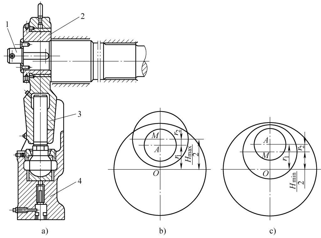
a) Adjustable stroke mechanism
b) Maximum operating stroke
c) Minimum operating stroke
1—Eccentric shaft
2—Eccentric sleeve
3—Connecting rod
4—Slider
O—Main shaft center
A—Eccentric part center of the eccentric main shaft
M—Center of the eccentric sleeve
When the eccentric distances of the eccentric shaft and the eccentric sleeve are in the same direction, the value of the operating stroke is maximum, as shown in Figure 43b, that is,
Hmax=2(r1+r2)
Where
- Hmax—Maximum operating stroke of the press (mm);
- r1—Eccentric radius of the eccentric shaft (mm);
- r2—Eccentric radius of the eccentric sleeve (mm).
When the eccentric distances of the eccentric shaft and the eccentric sleeve are in opposite directions, the value of the operating stroke is minimum, as shown in Figure 43c, that is,
Hmin=2(r1-r2)
Where Hmin-Minimum operating stroke of the press (mm).
Figure 44 shows a schematic diagram of the eccentric press stroke adjustment mechanism. The principle and steps for adjustment are as follows:
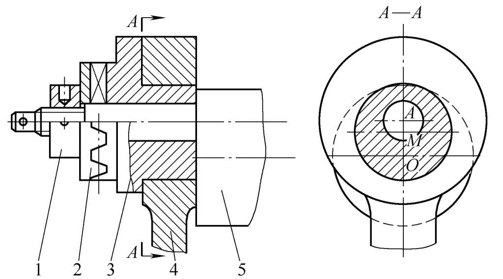
1—Nut
2—Engagement sleeve
3—Eccentric sleeve
4—Connecting rod
5—Eccentric main shaft
The front end of the eccentric main shaft 5 is an eccentric part, which is sleeved with an eccentric sleeve 3. The eccentric sleeve 3 and the engagement sleeve 2 are meshed by end teeth and locked by the nut 1. The engagement sleeve 2 is connected to the eccentric main shaft 5 by a key. The connecting rod 4 is freely sleeved on the eccentric sleeve. In this way, the rotation of the main shaft will drive the center M of the eccentric sleeve 3 to move in a circular motion along the center O of the main shaft, thus making the connecting rod 4 and the slider perform a reciprocating up and down movement.
Loosen the nut 1 to disengage the end teeth of the engagement sleeve 2, rotate the eccentric sleeve 3, and adjust the distance from the center M of the eccentric sleeve to the center O of the main shaft, thereby adjusting the stroke of the slider within a certain range. The adjustment range of the stroke is ![]() (where A is the center of the eccentric part of the eccentric main shaft, and M is the center of the eccentric sleeve).
(where A is the center of the eccentric part of the eccentric main shaft, and M is the center of the eccentric sleeve).
(2) Adjustment of the press shut height
To accommodate molds of different heights, the die height of the press must be adjustable. In general, the length of the connecting rod of the press can be adjusted.
One end of the connecting rod of the press is connected to the crankshaft, and the other end is connected to the slider. Therefore, adjusting the length of the connecting rod can achieve the purpose of adjusting the die height. The crank slider mechanism of the JB23-63 press shown in Figure 45 adjusts the die height by adjusting the length of the connecting rod.
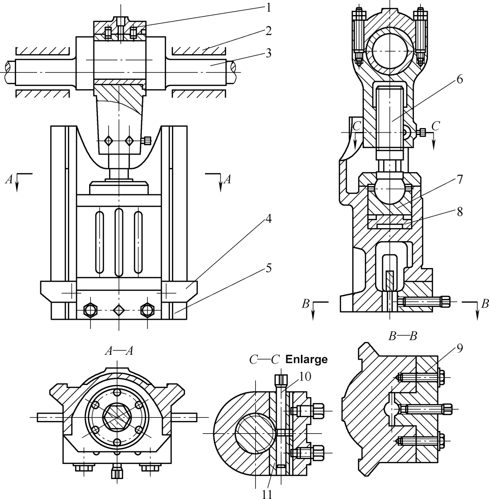
1—Connecting body
2—Bearing bush
3—Crankshaft
4—Striker bar
5—Slider
6—Adjustment screw
7—Support seat
8—Safety block
9—Die holder clamping block
10—Locking screw
11—Locking block
As can be seen in Figure 45, the connecting rod is not an integral part but is composed of the connecting body 1 and the adjustment screw 6. There is a hexagonal section in the middle of the adjustment screw 6, as shown in section A-A of Figure 44. Loosen the locking screw 10 and use a wrench to turn the hexagonal part in the middle of the adjustment screw 6 to adjust the length of the connecting rod. Larger presses adjust the screw via a motor, gear, or worm gear mechanism.
When the slider is at the bottom dead center, the distance between the lower plane of the slider and the table surface is called the shut height of the press. When the connecting rod is adjusted to its minimum length, the shut height reaches its maximum value, referred to as the maximum shut height of the press; when the connecting rod is adjusted to its maximum length, the shut height reaches its minimum value, referred to as the minimum shut height of the press.
In order to correctly install the mold on the press and ensure the normal operation of the stamping process, the maximum closed height of the press must be greater than the closed height of the mold, so that the mold can be installed between the working surface of the press and the lower surface of the slider; the minimum closed height of the press must be less than the closed height of the mold so that the upper and lower molds can align properly during stamping.
After adjusting the closed height of the press, the locking device must be locked to prevent the connecting rod length from changing due to looseness during the operation of the press, affecting the normal stamping operation. This is especially important for certain stamping processes in the basic deformation procedures, such as bending and embossing.
(3) Adjustment of the Knockout Device
After the end of a stamping operation, the workpiece often gets stuck in the mold. To push the workpiece out, the press usually has a knockout device set on the slider. As shown in Figure 46, the rigid knockout device consists of a knockout rod 4 passing through the slider and a stop screw 3 fixed to the machine body.
When the slider descends to perform stamping, the workpiece is pushed up by the ejector rod 7 in the upper die through the knockout rod 4 in the slider. When the slider ascends and approaches the top dead center, both ends of the knockout rod 4 are blocked by the stop screw 3 on the machine body. As the slider continues to rise, the knockout rod 4 moves downward relative to the slider, pushing the ejector rod 7 in the upper die to eject the workpiece.
The maximum working stroke of the knockout rod 4 is H-h. If the knockout rod 4 collides with the stop screw 3 too early, equipment accidents will occur. Therefore, when changing molds or adjusting the installation height of the press, the position of the stop screw 3 must be adjusted accordingly.
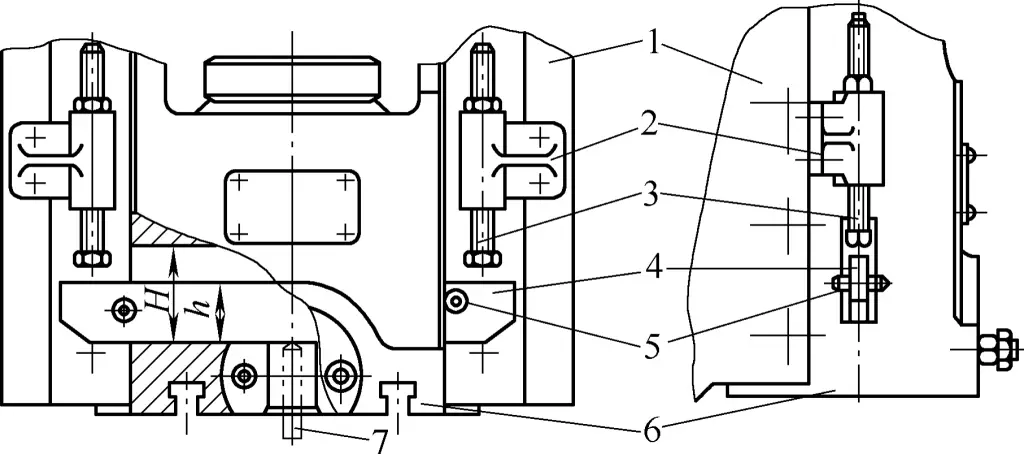
1—Machine Body
2—Stop Seat
3—Stop Screw
4—Knockout Rod
5—Stop Pin
6—Slider
7—Ejector Rod
Figure 47 shows the initial working state of the press knockout device.
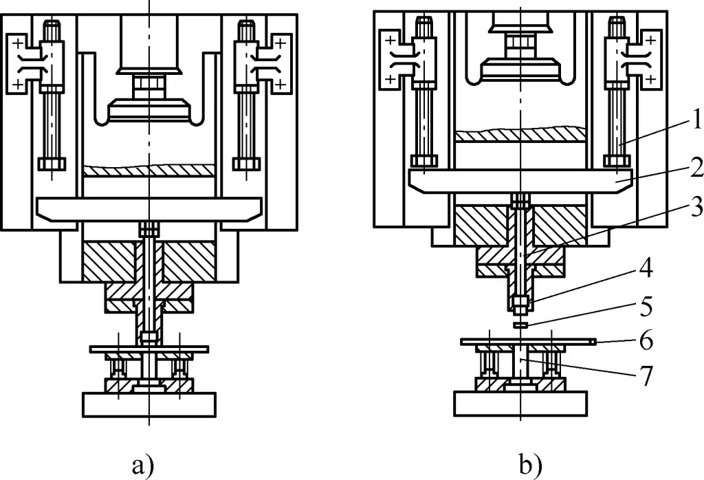
a) Bottom Dead Center of Stroke
b) Top Dead Center of Stroke
1—Stop Screw
2—Knockout Rod
3—Ejector Rod
4—Female Die
5—Stamped Part
6—Sheet Material
7—Punch
4. Installation and Adjustment of the Blanking Die
The installation and adjustment of the stamping die is an important part of the stamping operation. The quality of the installation and adjustment directly affects the safety and production of the processed parts. The correctness of the installation and adjustment directly affects the safety of the mold, the equipment, and the stamping workers.
(1) Installation Method of the Blanking Die
The general installation principle of the die on the press is: first fix the upper die on the slider of the press, and then adjust the lower die according to the position of the upper die. Corresponding adjustments of the press must be made during the mold installation process.
The installation of blanking dies can be divided into non-guided blanking dies and guided blanking dies.
1) Installation of Non-Guided Blanking Dies
The installation of non-guided blanking dies is relatively complicated. The method is as follows:
① Preparation for Mold Installation. Before installing the mold, the press and the mold should be inspected. The main inspection items include:
- The nominal pressure of the selected press must be 1.2-1.3 times greater than the process force of the mold.
- The positions of the mounting holes (slots) of the mold must match those of the press.
- The size of the scrap hole on the working table of the press should be larger than the size of the product and scrap. If the workpiece or scrap falls directly on the working table, space should be reserved for manual removal.
- The size of the working table and the lower surface of the slider of the press should match the installed die, and there should be some clearance. Generally, the working table of the press should be 50-70mm larger than the die plate size.
- The length and diameter of the ejection rod of the die should match the knockout mechanism of the press.
In addition, the operators should be familiar with the shape, dimensional accuracy, and technical requirements of the parts to be punched, understand the relevant process documents of the punched parts and the processing content of the current process; be familiar with the type, structure, working principle, and usage characteristics of the blanking die used. Finally, the mold and the working table of the press should be cleaned, and the working state of the press should be checked.
② Check the installation conditions of the die. The closed height of the die must match the installation height of the press. Before installing the die, its closed height must be measured. The value of the closed height H0 of the mold should meet the following requirements:
Hmin+10mm≤H0≤Hmax-5mm
Formula
- H0-Closed height of the mold (mm);
- Hmax-Maximum closed height of the press (mm);
- Hmin-Minimum closed height of the press (mm).
If the closed height of the mold is too small and does not meet the above requirements, a ground pad can be added to the working table of the press to meet the above requirements before installing the mold, as shown in Figure 48.
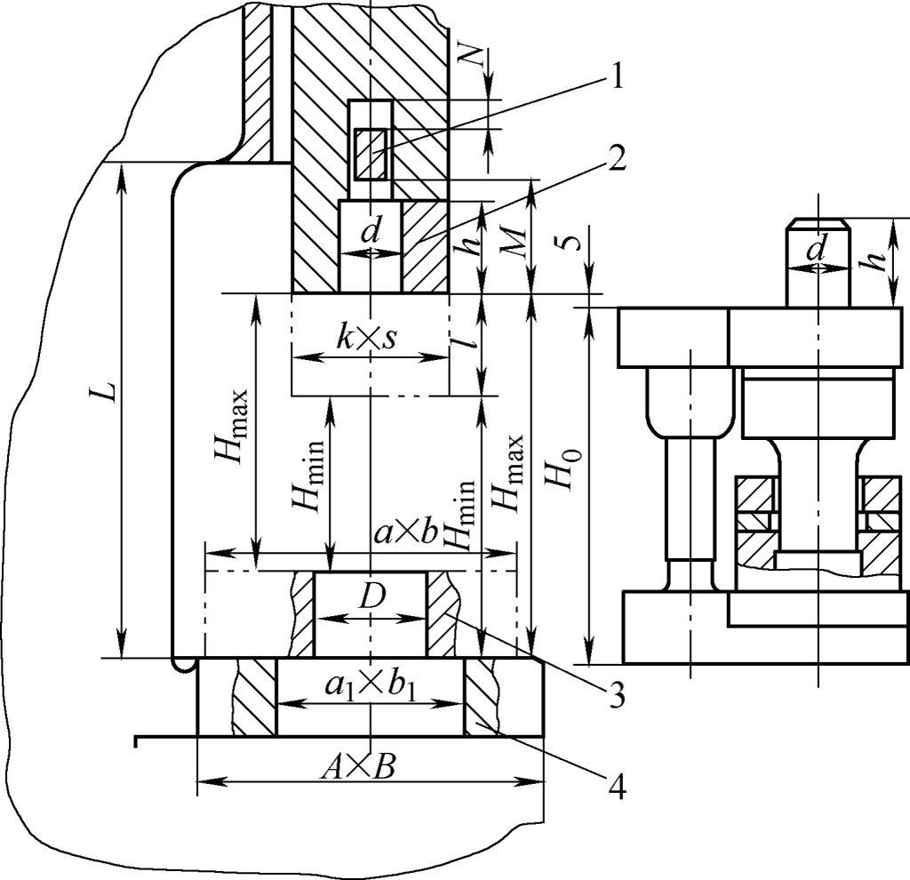
1—Ejection Beam
2—Mold Handle Clamping Block
3—Pad
4—Working Table
The significance of the other dimensions shown in the figure is:
- N – Stroke of the hitting crossbar;
- M – Distance between the hitting crossbar and the lower surface of the slider;
- h – Depth of the die handle hole or the height of the die handle;
- d – Diameter of the die handle hole or the die handle;
- k×s – Dimensions of the slider base surface;
- L – Distance from the workbench surface to the slider guide rail;
- l – Adjustment amount of mold height (closed height adjustment);
- a×b – Dimensions of the backing plate;
- D – Diameter of the backing plate hole;
- a1×b1 – Dimensions of the workbench hole;
- A×B – Dimensions of the workbench.
When multiple sets of dies are installed on the same press machine for multi-station stamping, the closing height of each set of dies should be the same.
③ Install the die. After completing the preparation work for the installation of each die, proceed with the die installation according to the following steps.
Place the die at the center of the press machine as shown in Figure 49. The upper and lower dies are propped up by blocks 3.
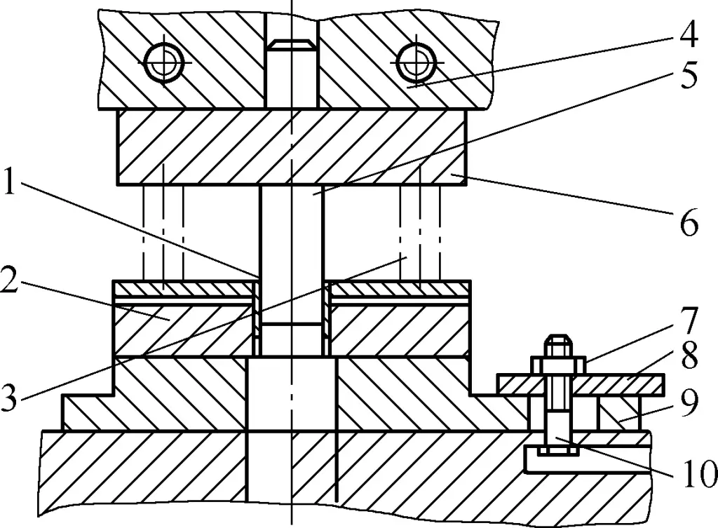
1—Hard cardboard
2—Die
3—Block
4—Press machine slider
5—Punch
6—Upper template
7—Nut
8—Pressure plate
9—Backing iron
10—T-bolt
Loosen the nut on the press machine slider 4, manually or with a pry bar turn the press machine flywheel to lower the press machine slider 4 until it contacts the upper template 6 and the die handle enters the die handle hole of the press machine slider 4.
If the press machine slider 4 adjusted to the lowest position as per the above requirements still cannot contact the upper template 6, then adjust the screw on the press machine connecting rod to make the press machine slider 4 contact the upper template 6. If adjusting the connecting rod to the lowest point still cannot make the press machine slider 4 contact the upper template 6, then add blocks at the bottom of the lower template to raise the lower template until it contacts.
After adjusting the height of the press machine slider 4, fasten the die handle to the press machine slider 4.
④ Adjust the die gap. After the die installation on the press machine is completed, adjust the gap between the punch and the die, that is, place hard cardboard 1 or copper sheet with a thickness equivalent to the single-sided gap value between the punch and the die on the cutting edge of the die 2, and use the light-tunneling method to adjust the gap between the punch and the die to make it uniform.
⑤ Fix the die. After adjusting the gap, insert the T-bolt 10 into the slot of the press machine table and tightly fasten the lower die to the press machine through the pressure plate 8, blocks 9, and nuts 7. Note that the bolts should be fastened symmetrically and alternately.
⑥ Die trial. After completing all the above work, the press machine can be started to conduct a trial run of the die. During the trial run, if the gap between the punch and die needs adjustment, slightly loosen the nut 7, and gently hammer the lower template in the adjustment direction with a hammer according to the distribution of the punch and die gap until the gap is suitable.
⑦ Formal production. After the trial-run workpiece is inspected and approved by self-inspection and inspection personnel, mass production can be commenced.
2) Installation method of guided cutting die
For guided cutting dies, due to the guidance of guide posts and guide sleeves, installation and adjustment are more convenient and easier compared to non-guided cutting dies. The main points of installation are:
- According to the installation requirements of non-guided cutting dies, make technical preparations before installing the die, clean the die and the press machine table, and inspect the press machine.
- Place the die in the closed state on the table of the press machine.
- Separate the upper and lower dies, and prop up the upper die with wooden blocks or backing iron.
- Lower the press machine slider to the bottom dead point and adjust it to contact the upper plane of the die upper template, as shown in Figure 50.
- Separately fasten the upper and lower dies to the press machine slider and press machine table. The bolts should be fastened symmetrically and alternately. When adjusting the position of the press machine slider, ensure that at the top dead point, the punch does not protrude beyond the guide plate, or the guide sleeve does not descend more than 1/3 of the guide post length.
- After the die is firmly fastened, conduct a trial run, and after a successful trial run, proceed to formal production.
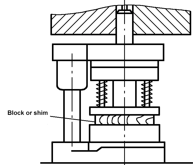
(2) Key points of cutting die adjustment
The key points of cutting die adjustment are:
1) Adjust the fit depth of the punch and die
Adjust the upper and lower dies of the cutting die to ensure the appropriate depth of engagement between the working parts of the upper and lower dies. It should not be too deep or too shallow, aiming to produce suitable parts. Generally, the cutting die ensures the punch enters the die to a depth of 0.5-1mm, and for hard alloy dies, it should not exceed 0.5mm. The fit depth of the punch and die is achieved by adjusting the length of the press machine connecting rod.
2) Adjust the gap between the punch and die
The cutting die must ensure a uniform gap around the punch and die. Inappropriate or uneven gaps will directly affect the quality of the stamped parts.
For guided component cutting dies, installation and adjustment are relatively convenient, as long as the guiding component movement accuracy is ensured because the fit between the guiding components (such as guide posts and guide sleeves) is relatively precise, ensuring a uniform fit gap between the upper and lower dies.
For non-guided cutting dies, pure copper foil or hard cardboard can be lined around the cutting edge of the die for adjustment (pure copper foil or hard cardboard thickness is equivalent to the single-sided gap between the punch and die). When the blank thickness of the stamped part exceeds 1.5mm, due to the larger die gap, the aforementioned lining method can be used for adjustment.
For blanking dies of thinner workpieces, the die can be adjusted by the stamping worker by observing the size of the gap around the mating punch and die. If it is found that the gap between the punch and the die is relatively large in a certain direction, the upper die should be fixed first, and the lower die should be loosened. Then, using a hammer, gently tap the side of the lower die towards the direction where the gap should be reduced. After appropriate adjustment, repeat the observation of the gap around the mating punch and die until it is uniform.
For blanking dies with straight-edge cutting edges, the method of light transmission and feeler gauge testing can be used to adjust the gap. When the punch and die are centered and the gap is uniform, use screws to secure the die to the press for trial punching.
After trial punching, inspect the trial punched parts to check for significant burrs and rough cut surfaces. If unsuitable, loosen the lower die and continue to adjust according to the previous method until the gap is appropriate.
To facilitate the adjustment of the gap for non-guided blanking dies in future production, the method of pressing a pure copper sheet or hard paper sheet with a thickness equal to the single-sided gap of the punch and die into the die cavity along with the punch can be used to reduce the workload of adjusting the blanking die.
3) Adjust the positioning device
The positioning components of the blanking die mainly include positioning pins, positioning blocks, and positioning plates. When adjusting the blanking die, check whether the positioning components meet the positioning requirements and if the positioning is reliable. If the positioning component positions are not suitable, they should be trimmed during adjustment, and if necessary, replaced.
4) Adjust the stripping system
The adjustment of the stripping system mainly involves checking whether the stripper plate or ejector functions smoothly, whether the stripping springs and rubber elasticity are sufficient, whether the stripping stroke is adequate, whether the scrap holes are unobstructed, and whether the punch rods and pusher rods can smoothly discharge parts and waste. If any faults are found, adjustments should be made, and if necessary, replacements should be made.
5. Precautions for blanking operations
The equipment used for blanking mainly includes various crank presses. During operation, it is first necessary to be familiar with the performance and characteristics of the equipment used and master its operation methods. Secondly, it is also important to understand the performance and characteristics of the die used for blanking and be able to install and adjust it. In addition, when performing blanking operations, attention should be paid to following the operating procedures, with the main requirements being the following points.
(1) Requirements before work
- Prepare personal protective equipment and tools to be used.
- Check the shift handover records, and pay attention to any unresolved issues from the previous shift.
- Check whether the easily loosened parts on the equipment are tightened.
- Check whether the pressure in the oil and gas systems is appropriate and whether there is any leakage in the pipelines.
- Lubricate the equipment as required.
- Review process files and production task sheets, including: check the molds used and their installation status, verify the material specification and grade, quantity of the blanking pieces, and other relevant items specified in the process files.
(2) Requirements during work
1) Connect the power, and after the flywheel rotates normally, make the press run empty a few times to check whether the clutch, brake, and control system are sensitive and reliable; check whether the safety devices are effective; at the same time, observe whether the mold works normally.
2) Test several workpieces, perform self-inspection and have the inspector check them. Only proceed with normal production if they are qualified.
3) During work, if quality problems or abnormal operation of the press, malfunction of controls, or insensitive response of the clutch and brake occur, stop the machine immediately. It is strictly forbidden to run the equipment with faults.
(3) Requirements after completing the work
- Disengage the clutch and turn off the power.
- Clean the workplace, wipe the press and mold, and apply protective oil as required.
- Carefully record the shift handover details.
6. Common defects of blanking pieces and solutions
Common defects of blanking pieces include large burrs and warped surfaces. These defects may be caused by issues with the blanking material, adjustment or problems with the blanking mold, or operation negligence. Solutions should be devised based on a careful analysis of the causes of the defects. Refer to Table 7 for common defects and solutions of blanking pieces.
Table 7 Common defects and solutions of blanking pieces
| Quality status | Cause | Solution |
| The sheared section is good with only small burrs and a certain inclination on the cut surface. | Reasonable and uniform gap, sharp cutting edges of punch and die, and overlapping shear cracks. | This is a normal situation. |
| The cut surface has cracks, double bright bands, and burrs, the punching size is reduced, and the blanking size is increased. | The gap is too small, and the cracks at the cutting edges of the punch and die do not overlap. | Sharpen the cutting edges of the punch and die. |
| The cut surface’s inclination is large, forming torn burrs, enlarged fillets, increased punching size, and reduced blanking size. | The gap is too large and the cracks do not overlap. | Replace the cutting edges of the punch and die. |
| Burr distribution on the cut surface is uneven, and the fillet is inconsistent. | 1) The axes of the punch and die are misaligned or not coaxial. 2) The gap in the guiding device is too large. 3) The guiding device or punch is skewed. | 1) Adjust the relative position of the punch and die or sharpen the cutting edges. 2) Replace the guiding device (such as guide bush). 3) Reinstall the guiding device or punch. |
| Large burrs on the edges of punched pieces and increased fillets of blanked pieces. | The cutting edge of the die is dull or not hard enough. | Sharpen or replace the die. |
| Large burrs on blanked pieces and large fillets on punched pieces. | The cutting edge of the punch is dull or not hard enough. | Sharpen or replace the punch. |
| Both blanked and punched pieces have large burrs and large fillets. | Both punch and die are dull. | Sharpen or replace both punch and die. |
| The plane of the workpiece is concave. | 1) The cutting edge of the die has a reverse taper. 2) The contact area between the ejector rod and the workpiece is too small. 3) The stripper plate is fixed. 4) Blanking through the die hole | 1) Sharpening the die edges 2) Replacing the ejector pin 3) Switching to an elastic stripper plate 4) Improving the ejection mechanism |
| Offset of the workpiece inner hole | 1) Misalignment of the positioning ring and the die 2) Misalignment of the material stopper and feeding device | 1) Replace the positioning ring 2) Reassemble or replace relevant parts |
IV. Gas Cutting
Gas cutting uses the thermal energy of an oxy-acetylene flame or an oxygen-liquefied gas flame to preheat the cutting area of a workpiece to a certain temperature and then sprays a high-speed cutting gas stream to make the metal burn and release heat, thereby achieving cutting.
Gas cutting has the advantages of convenience and strong adaptability. It can realize the cutting of all thicknesses and types of carbon steel, including steel plates and structural steel. Additionally, gas cutting offers low production costs.
Gas cutting is classified by the different flames generated by the cutting gases, such as oxy-acetylene flame cutting and oxygen-liquefied petroleum gas cutting. Based on operation methods, it is divided into manual gas cutting, semi-automatic gas cutting, and CNC automatic gas cutting. Oxy-acetylene manual gas cutting is the most widely used method in sheet metal processing.
1. Gas Cutting Equipment and Tools
Equipment and tools used for gas cutting vary slightly depending on the type of combustible gas used. Oxy-acetylene flame cutting equipment consists of an oxygen cylinder and oxygen regulator, acetylene cylinder and acetylene regulator, flashback arrestor, and torch, as shown in Figure 51.
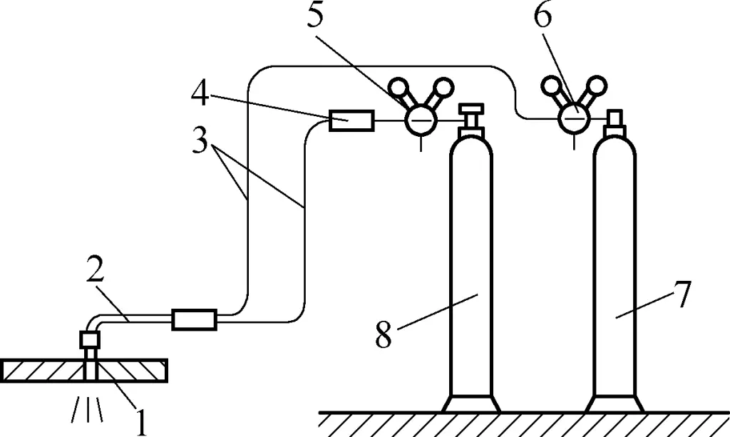
1—Workpiece
2—Torch
3—Hose
4—Flashback Arrestor
5—Acetylene Regulator
6—Oxygen Regulator
7—Oxygen Cylinder
8—Acetylene Cylinder
(1) Oxygen Cylinder and Acetylene Cylinder
The oxygen cylinder is a cylindrical container for storing high-pressure oxygen and is painted light blue for identification. The maximum pressure is 16.7 MPa, with a volume of about 40L and a gas capacity of about 6m3. The oxygen cylinder is a high-pressure vessel with explosion risks, requiring safety precautions during use. It should be handled with care to avoid severe vibrations and impacts, and kept more than 5 meters away from open flames or heat sources during operation.
In summer, oxygen cylinders should be protected from sun exposure, and in winter, frozen valves should not be thawed with fire but with hot water. The oxygen in the cylinder should not be completely depleted; the residual pressure should be maintained between 98–196 kPa to prevent the ingress of other gases and potential explosions.
Acetylene cylinders are specialized containers for storing and transporting acetylene. They resemble oxygen cylinders but are slightly shorter (1.12m) and have a larger diameter (250mm). The surface is painted white, with “acetylene” marked in red. To ensure the stable and safe storage of acetylene, the cylinder is filled with a porous material soaked in acetone.
Acetylene cylinders should be kept upright during handling, loading, unloading, and use, and should never be laid flat on the ground. The use of acetylene requires a pressure regulator; direct use is prohibited.
(2) Regulator.
The regulator is a device that reduces high-pressure gas to low-pressure gas. Its function is to reduce the pressure of the high-pressure gas from the cylinder to the desired working pressure and maintain pressure stability.
Figure 52 shows the structural principle of a single-stage regulator. Turning the adjustment screw 1 clockwise opens the pressure control valve 8, allowing high-pressure gas from the cylinder to flow from the high-pressure chamber 7 through the pressure control valve 8 into the low-pressure chamber 12. The gas expands, reducing the pressure to the working pressure, and then exits through the outlet 11.
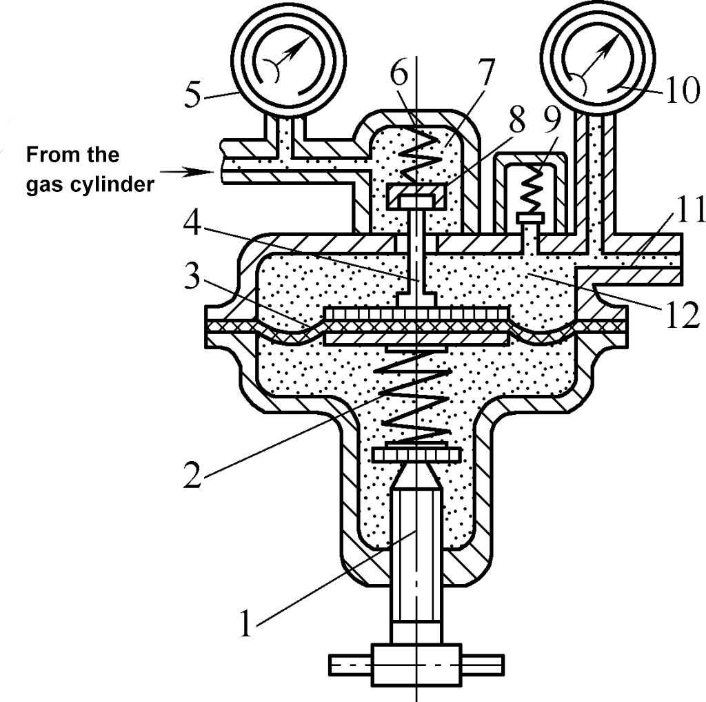
1—Adjustment Screw
2—Working Spring
3—Elastic Diaphragm
4—Transmission Rod
5—High-Pressure Gauge
6—Auxiliary Spring
7—High-Pressure Chamber
8—Pressure Control Valve
9—Safety Valve
10—Low-Pressure Gauge
11—Outlet
12—Low-Pressure Chamber
The working pressure is adjusted by changing the position of adjustment screw 1. The working spring 2 and auxiliary spring 6 ensure that the pressure control valve 8 can automatically open and maintain balance as the cylinder pressure gradually decreases, keeping the working pressure stable.
Regulators for oxygen and dissolved acetylene gas must be specialized regulators that match the characteristics of each gas.
(3) Torch and Hose.
The function of the torch is to mix oxygen and acetylene in the correct proportion to form a preheat flame, and to spray high-pressure oxygen onto the workpiece being cut, causing the metal in the oxygen jet to burn, blow away, and form a cut.
The cutting torch is divided into two types, jet type and equal pressure type, according to the different mixing methods of oxygen and acetylene, as shown in Figure 53. Of these, the jet type cutting torch is the most commonly used and is suitable for low pressure or medium pressure acetylene gas. Table 8 lists the common models and parameters of the jet type cutting torch.

a) Principle and shape of jet type
b) Shape of equal pressure type
1—Cutting nozzle
2, 9—Mixing tube
3—Jet tube
4—Nozzle
5, 10—Oxygen valve
6—Oxygen conduit
7—Acetylene conduit
8—Acetylene valve
Table 8 Common models and parameters of jet type cutting torch
| Model | Cutting nozzle | Thickness of low carbon steel plate/mm | Oxygen hole diameter of cutting nozzle/mm | Gas pressure/MPa | Gas consumption/(L/min) | |||
| Number | Type | Oxygen | Acetylene gas | Oxygen | Acetylene gas | |||
| G01—30 | 1 | Ring shape | 3~10 | 0.7 | 0.2 | 0.001~0.1 | 13.3 | 3.5 |
| 2 | 10~20 | 0.9 | 0.25 | 23.3 | 6.0 | |||
| 3 | 20~30 | 1.1 | 0.3 | 36.7 | 5.2 | |||
| G01—100 | 1 | Plum blossom shape | 10~25 | 1.0 | 0.3 | 36.7~45 | 5.8~6.7 | |
| 2 | 25~50 | 1.3 | 0.4 | 58.2~71.7 | 7.7~8.3 | |||
Note: In the model number, G represents the cutting torch, 0 represents manual, 1 represents jet type, and the following numbers represent the maximum thickness (mm) of low carbon steel for gas cutting.
Figure 53a shows the jet type cutting torch. The jet type cutting torch uses a fixed jet tube, and by replacing the cutting nozzles with different oxygen hole diameters, it can meet the needs of cutting workpieces of different thicknesses. It is widely used in production.
When working, preheat oxygen enters the mixing chamber at high speed, draws in the surrounding acetylene gas and forms a mixture with a certain ratio, which is sprayed out from the cutting nozzle. After ignition, it forms a preheating flame. Cutting oxygen then exits from the central hole of the cutting nozzle through the oxygen tube, forming a high-speed cutting oxygen flow.
Figure 53b shows the equal pressure type cutting torch. The equal pressure type cutting torch’s acetylene, preheating oxygen, and cutting oxygen are respectively introduced into the cutting nozzle through separate pipelines. Preheating oxygen and acetylene begin to mix in the cutting nozzle, and after being sprayed out and ignited, they produce a preheating flame. It is suitable for medium-pressure acetylene gas and is characterized by a stable flame and is not prone to flashback.
The rubber hose used to transport oxygen, acetylene gas, or liquefied petroleum gas to the cutting torch is made of high-quality rubber with woven fabric or cotton fiber. The allowable working pressure for the oxygen hose is 1.5MPa, and the hose diameter is 8mm; the allowable working pressure for the acetylene hose is 0.5MPa, and the hose diameter is 10mm. For easy identification, the oxygen hose is red, and the acetylene hose is green.
2. Gas cutting operation techniques
General gas cutting can be performed according to the following steps and methods:
(1) Preparation before gas cutting.
Clean the oil stains and rust on the surface of the workpiece, and elevate the workpiece to a certain height, leaving a certain gap below the workpiece to facilitate the expulsion of oxide slag.
Then, check the shape of the cutting oxygen flow line. During inspection, ignite the cutting torch and adjust the oxygen-acetylene mixture ratio to make the preheating flame a neutral flame. The simplest and most practical way to judge the nature of the oxyacetylene flame is to observe its shape.
The length of the neutral flame is moderate, with three distinct parts: the flame core, inner flame, and outer flame (see Figure 54a); the reducing flame is longer and brighter, and the inner flame is more prominent (see Figure 54b); the oxidizing flame is shorter, with no obvious boundary between the inner and outer flames, and the brightness is darker (see Figure 54c).

1—Flame core
2—Inner flame
3—Outer flame
After adjusting the preheating flame to a neutral flame, repeatedly release the cutting oxygen and adjust the mixture adjustment valve to ensure that the oxyacetylene flame can remain neutral during the cutting process. Observe the shape of the cutting airflow (commonly known as the air line) from different sides, requiring it to be uniform and clear cylindrical. Otherwise, turn off the acetylene and oxygen and use a cleaning needle to clear the cutting nozzle until the standard cutting airflow is obtained.
(2) Gas cutting.
If starting cutting from the edge of a steel plate, preheat the edge of the plate first. When the preheating point turns slightly red, move the center of the preheating flame outside the edge, slowly open the cutting oxygen valve, and observe the oxidized molten slag flying out with the oxygen flow at the cut. When the cut through, slowly move the cutting torch to continue cutting, as shown in Figure 55.
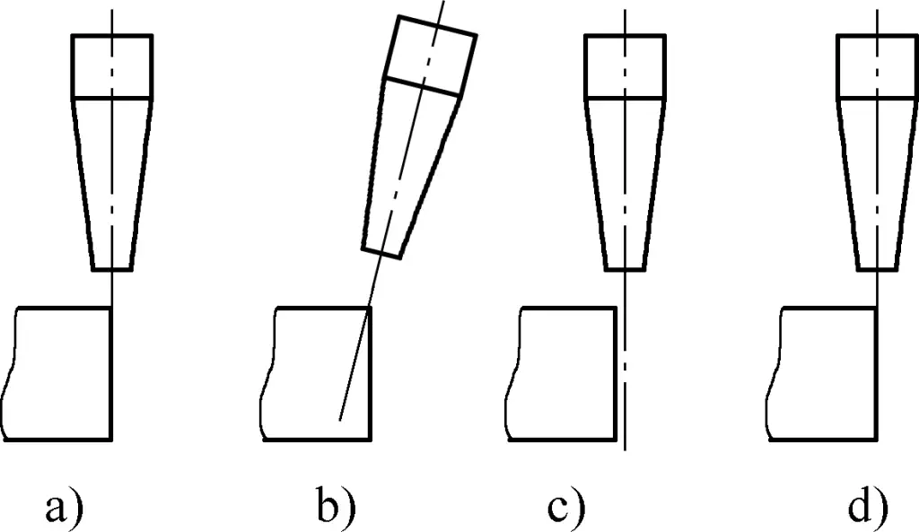
a), b) Preheating
c) Moving back and releasing oxygen
d) Starting the cut
The cutting speed should be determined according to the thickness of the steel plate and the quality requirements of the cutting surface.
In actual work, there are two methods to determine whether the cutting speed is appropriate: Observe the cutting surface striation. If the striation is uniform and the back-drag is minimal, it indicates that the cutting speed is suitable; During the cutting process, observe the cutting from the upper part along the cutting airflow direction. If the cutting speed is appropriate, the airflow at the cutting site should be smooth without obvious bending.
To fully utilize the preheating flame and improve efficiency during cutting, the cutting nozzle can be tilted backward by 0°~30° in the opposite direction of the cutting progress according to the thickness of the steel plate being cut; the thinner the steel plate, the larger the angle, as shown in Figure 56.
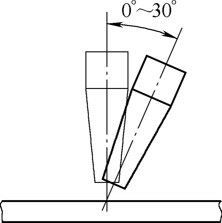
If a hole needs to be made at a certain position in the middle of the steel plate, attention should be paid to controlling the distance and angle of the cutting nozzle from the steel plate when opening the cutting oxygen to avoid the splashed slag blocking the cutting nozzle, as shown in Figure 57.
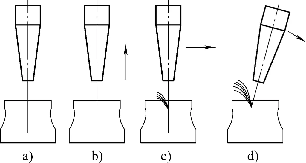
a) Preheating
b) Lifting the cutting nozzle
c) Start cutting oxygen, move the torch backward
d) Tilt the torch
The posture for holding the torch during gas cutting is: Hold the handle of the torch with the right hand, support the cutting oxygen adjustment valve with the thumb, index, and middle fingers of the left hand. Whether standing or squatting, maintain a stable center of gravity, relax arm muscles, breathe naturally, hold the torch steadily, and move both arms slowly according to the cutting speed requirements or follow the body’s movement. The main body of the torch should be parallel to the upper surface of the object being cut.
During the cutting process, backfire often occurs due to insufficient oxygen or acetylene gas supply, slag blocking the cutting nozzle, or overheating of the nozzle head. In this case, the gas source should be closed urgently. The correct sequence is: First close the acetylene gas valve to cut off the flammable gas source, then close the mixed gas valve. After identifying and resolving the cause, reignite and continue working.
(3) End of gas cutting.
After cutting to the endpoint, close the cutting oxygen valve and lift the torch simultaneously. If it is not needed for further use, first close the acetylene gas valve and finally close the mixed gas adjustment valve. Loosen the pressure regulator’s adjustment screw, and close the acetylene gas and oxygen cylinder valves. After work is finished, remove the torch and pressure regulator and store them properly, coil up the acetylene and oxygen rubber hoses, and clean up the work site.
3. Gas cutting of low-carbon steel
Oxy-acetylene flame gas cutting is mainly used for cutting low-carbon steel and low-alloy steel. It is widely used for cutting steel plates and profiles for material preparation and beveling of weldments before welding and cutting various complex-shaped plates.
(1) Gas cutting of steel plates
Oxy-acetylene flame gas cutting can cut low-carbon steel plates of different thicknesses, and the operation methods are different.
1) Gas cutting of 4~25mm thick steel plates.
For gas cutting 4~25mm thick steel plates, a G01-100 type cutting torch can be selected. During material preparation, ensure that the length of the cutting airflow (wind line) exceeds 1/3 of the thickness of the plate being cut. The distance between the cutting nozzle and the cutting piece is roughly equal to the length of the flame core plus 2~4mm. To improve cutting efficiency, the cutting nozzle can be tilted backward by an angle of 20°~30° during gas cutting.
2) Gas cutting of thin steel plates.
For gas cutting thin steel plates, a G01-30 type cutting torch and No. 2 cutting nozzle are often selected. To achieve better results, the preheating flame energy must be small, the cutting nozzle should be tilted in the opposite direction of the progress and form an angle of 25°~45° with the steel plate, the distance between the cutting nozzle and the cutting piece surface should be 10~15mm, and the cutting speed should be as fast as possible.
3) Gas cutting of thick steel plates.
When gas cutting thick steel plates, first start preheating at the edge corner of the cutting piece (see Figure 58a). Once preheated to the cutting temperature, gradually increase the cutting oxygen and tilt the cutting nozzle towards the cutting piece (see Figure 58b). After the edge of the cutting piece is fully penetrated, increase the cutting oxygen flow and make the cutting nozzle perpendicular to the cutting piece surface. Simultaneously, move the cutting nozzle along the cutting line. The cutting speed should be slow, and the cutting nozzle should perform a transverse crescent-shaped swing (see Figure 58c).
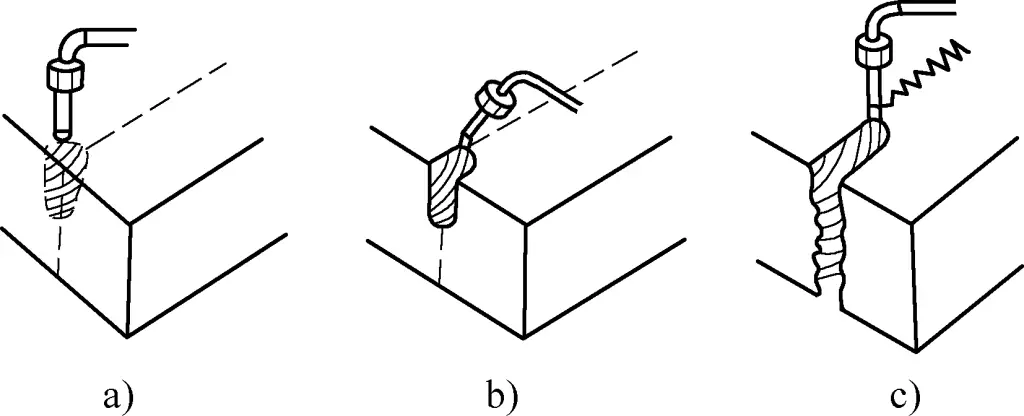
4) Cutting holes in steel plates.
When gas cutting flange ring type components, since it is impossible to start cutting from the edge of the plate, the cutting operation must start from the middle of the steel plate. After creating a hole in the steel plate, follow the cutting line for cutting.
The method for piercing a hole in the steel plate is shown in Figure 59. First, preheat the area where a hole is needed on the steel plate, hold the cutting nozzle perpendicular to the steel plate (see Figure 59a), and once heated to the cutting temperature, lift the cutting nozzle approximately 15mm away from the steel plate (see Figure 59b), then slowly open the cutting oxygen valve and tilt the cutting nozzle slightly (see Figure 59c).

a) Preheating
b) Lift the cutting nozzle
c) Slowly open the cutting oxygen valve
During the entire hole-piercing process, be careful not to face the steel plate surface to avoid being scalded by splashed slag.
5) Gas cutting of multi-layer steel plates.
When gas cutting several layered steel plates with the same shape, the steel plates are often stacked together to complete the cutting of multiple plates at once. For multi-layer steel plate cutting, the plates must be tightly pressed together, so a pressing device is needed (see Figure 60a), and the rust and dirt on the steel plate surface should be cleaned.
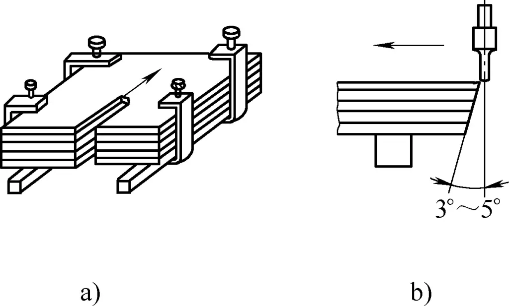
The upper layer of steel plates should be moved outward a bit (see Figure 60b) to facilitate the start of gas cutting. The cutting parameters should be determined according to the total thickness of the multi-layer steel plates. To avoid excessive melting of the upper layer of steel plates, a flat steel plate can be used as a cover plate for cutting.
(2) Gas cutting of steel pipes
During gas cutting of steel pipes, the preheating flame should be perpendicular to the surface of the steel pipe. Once fully cut through, tilt the cutting nozzle gradually until it is close to the tangent direction of the pipe material, then continue cutting.
Figure 61a shows fixed steel pipe gas cutting, starting preheating from the underside of the pipe material (viewed from below) in the direction indicated by 1 in the figure. When cutting to the upper part of the pipe material, close the cutting oxygen, move the torch to the underside of the pipe material again, and continue cutting in the direction indicated by 2 in the figure.
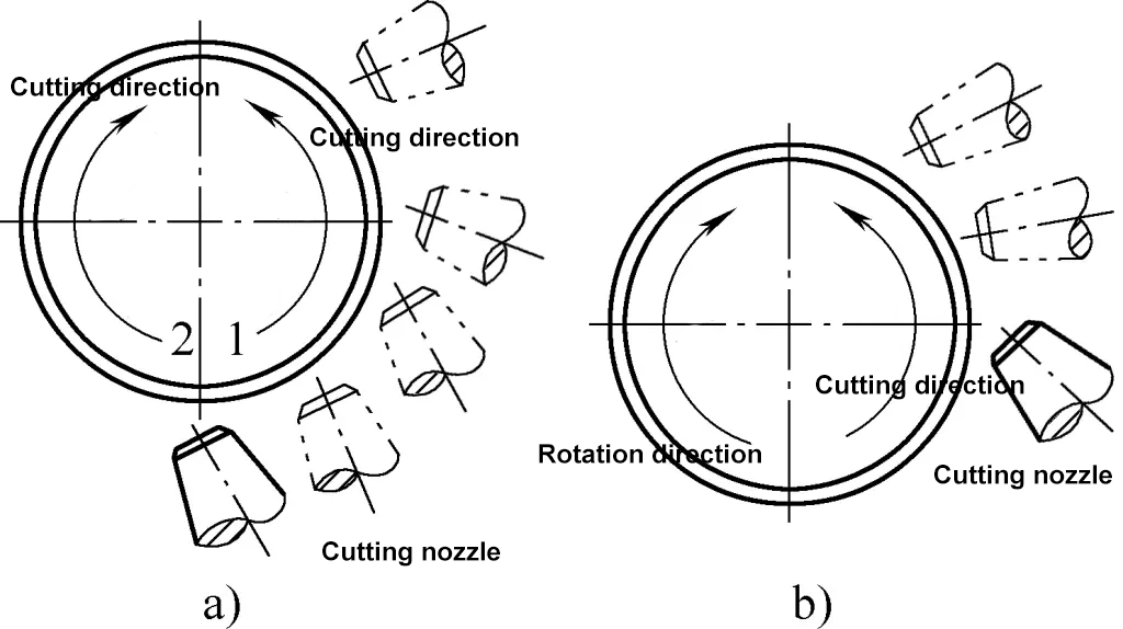
Figure 61b shows rotating pipe material gas cutting. Start preheating from the side of the steel pipe and cut along the cutting direction shown in the figure. After cutting a section, temporarily stop, slightly rotate the pipe material, and then continue cutting. Smaller diameter pipe material can be cut in 2-3 attempts, while larger diameter pipe material may require multiple attempts, but the fewer the better.
(3) Gas cutting of round steel
For gas cutting round steel, start preheating from one side of the round steel. The preheating flame should be perpendicular to the round steel surface. At the beginning of gas cutting, simultaneously open the cutting oxygen valve and turn the cutting nozzle to be perpendicular to the ground. Once the round steel is cut through, move the cutting nozzle forward and make slight horizontal swings.
It is best to complete the round steel cutting at once. If the diameter of the round steel is large and cannot be cut through in one attempt, the segmentation cutting method can be used as shown in Figure 62. The numbers in the figure indicate the cutting sequence during segmentation cutting of round steel.
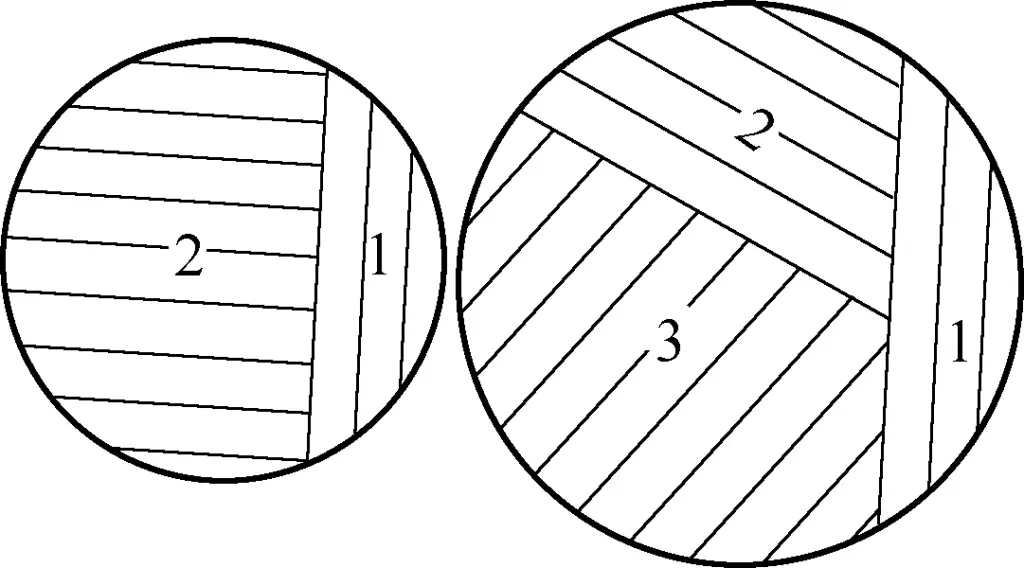
(4) Gas cutting of I-beams
When cutting I-beam with gas, the principle is to cut from bottom to top, as shown in Figure 63. This way, the remaining material will not fall and damage the cut or cause other accidents. During gas cutting, the cutting nozzle should be perpendicular to the cutting line.
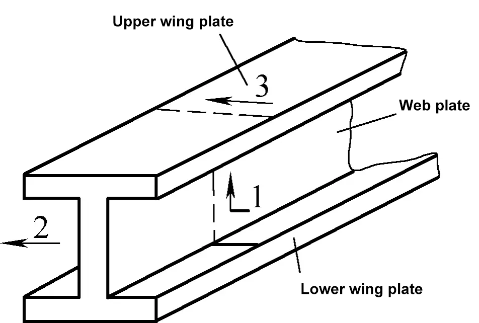
1—Complete one side of the lower flange and web in one cut
2—Gas cut the other side of the lower flange
3—Lastly, gas cut the top flange
(5) Gas cutting of channel steel
When gas cutting channel steel along a straight line, the cutting nozzle should be perpendicular to the cutting surface (see Figure 64a). For inclined cuts, the nozzle should be perpendicular to the web, and for the other two flanges, the nozzle should follow the direction of the inclined line on the web for gas cutting (see Figure 64b).
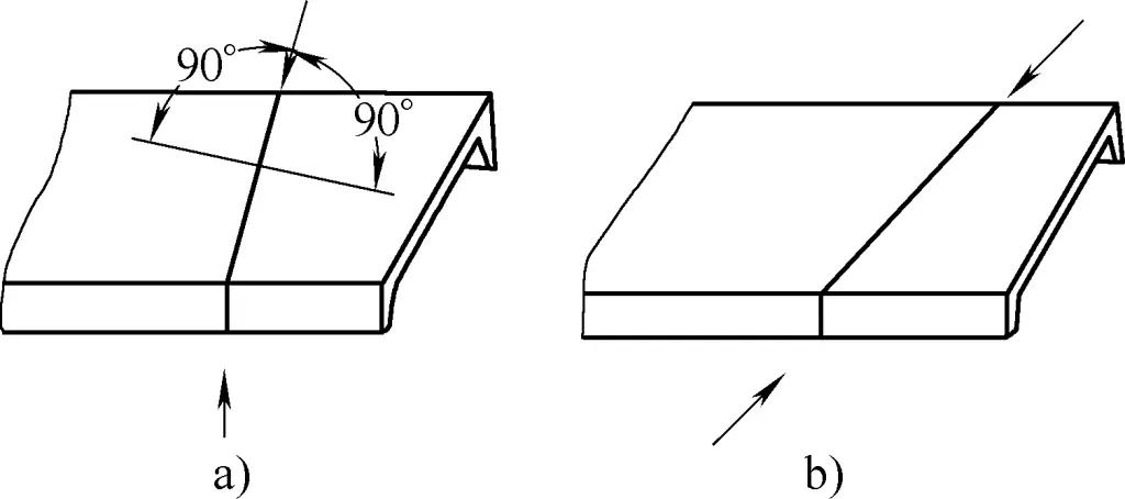
(6) Gas cutting of welding grooves
Compared to general gas cutting, gas cutting of welding grooves should be slightly faster, with a higher preheating flame power and slightly higher cutting oxygen pressure. Figure 65a shows the form used for gas cutting grooves in steel plates and pipes, while the method in Figure 65b is mainly used for cutting grooves in pipes.
When using the method shown in Figure 65b for gas cutting pipe grooves, the preheating flame power is lower than when using the method shown in Figure 65a, preventing burning of the blunt edge.
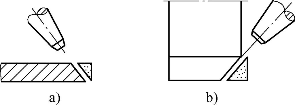
4. Precautions for gas cutting operations
The acetylene used in gas cutting is a flammable and explosive gas, while oxygen is a gas with a strong combustion-supporting effect and higher pressure. Oxygen cylinders, acetylene cylinders, and acetylene generators are all pressure vessels that pose certain risks during transportation, storage, and use.
Moreover, since open flames are used during gas cutting, the temperature is high, and a large amount of molten slag splashes around, increasing the risk of fire and explosion. Therefore, particular attention should be paid to safety and civilized production during gas cutting operations.
On the other hand, the quality of cut parts in gas cutting is closely related to the selection of cutting process parameters and manual operation posture. To ensure the quality of the cut parts, attention should also be paid to the selection of the gas cutting process specification during gas cutting operations.
(1) Safety precautions for gas cutting operations
To ensure safety during gas cutting operations, the following main precautions should be observed:
1) The gas cutting work area should meet safety requirements and be equipped with necessary firefighting facilities. The area should be free of flammable and explosive materials, well-ventilated, and maintain a certain level of humidity. It is strictly prohibited for cutting jets and molten slag to come into direct contact with cement surfaces. The acetylene generator, acetylene cylinders, and oxygen cylinders should be kept at a safe distance from the work area, generally 10 meters or more.
2) The steel plates or sections being cut in the work area should be neatly arranged and placed stably. There should be a certain amount of space behind the cutting area to facilitate the discharge of molten slag and prevent the accumulation of acetylene, which could cause an explosion.
Scrap and residual slag generated after cutting should be cleaned up promptly. During operation, the distribution direction of backfire preventers, oxygen and acetylene hoses should be reasonable to prevent them from being ignited by molten slag or being crushed by the cut parts.
3) The safety devices and equipment used for gas cutting should be safe and reliable. For example, backfire preventers should be sensitive and effective, pressure reducers should display accurately and be calibrated regularly. Oxygen cylinders and acetylene cylinders should have fixed placement locations, be arranged neatly, and be fixed with special brackets to prevent slipping or rolling.
4) Operators must be trained and qualified before performing gas cutting work and should strictly follow the safety operation procedures for gas cutting. Unauthorized use of gas cutting tools and equipment by others is strictly prohibited. During operation, personal protective equipment (such as gas welding goggles, work clothes, welding gloves, and necessary insulation shoes, guards, etc.) should be clean and complete.
(2) Quality precautions for gas cutting operations
To ensure the quality of cut parts during gas cutting operations, the following precautions should also be observed:
1) The appropriate specifications of the cutting torch and nozzle should be selected based on the thickness of the steel plate or section being cut.
2) Correctly choose the gas cutting process specification. When cutting with an oxy-acetylene flame, the distance between the nozzle and the workpiece surface is generally 3 to 5mm, and for thin plates with a thickness less than 4mm, a distance of 10 to 15mm is chosen. The gas pressure for manual cutting is shown in Table 9. The inclination angle of the nozzle relative to the workpiece surface is shown in Table 10.
Table 9 Gas pressure for manual cutting
| Steel plate thickness/mm | Cutting torch | Gas pressure/MPa | ||
| Type | Nozzle | Oxygen | Acetylene | |
| <3 | G01—30 | 12 | 0.3~0.4 | 0.001~0.12 |
| 3~12 | 12 | 0.4~0.5 | ||
| 12~30 | 2,3,4 | 0.5~0.7 | ||
| 30~50 | G01—100 | 3,4,5 | 0.5~0.7 | |
| 50~100 | 56 | 0.6~0.8 | ||
| 100~150 | G01—300 | 7 | 0.8~1.6 | |
| 150~200 | 8 | 1.0~1.4 | ||
| 200~250 | 9 | 1.0~1.4 | ||
Table 10 Inclination angle of the nozzle relative to the workpiece surface
| Workpiece thickness/mm | <10 | 10~30 | >30 | ||
| Inclination direction | Rearward tilt | Rearward tilt | Forward tilt at the start | Perpendicular after penetration | Rearward tilt at the end |
| Inclination angle | 0°~30° | 80°~85° | 80°~85° | 0° | 80°~85° |
During gas cutting, excessively low oxygen pressure can cause incomplete combustion of the metal, reducing the cutting speed and causing slag adherence between cuts. Excessively high oxygen pressure, on the other hand, can cause excess oxygen to act as a coolant, resulting in an uneven surface of the cut.
The optimal length of the cutting oxygen jet is about 500mm with a clear contour, ensuring smooth slag blowing and clean cuts with sharp edges. Otherwise, serious slag adherence and uneven cut width occur.
3) Pure oxygen should be used for cutting. If the purity is below 98%, impurities in the oxygen such as nitrogen will absorb heat during cutting, forming other compound films on the cut surface, hindering metal combustion, reducing the cutting speed, and increasing oxygen consumption.
4) The plates to be cut must be chemically descaled to remove any oxide layer; otherwise, backfire could occur, affecting the cutting quality.
5) For steels sensitive to hardening, the edges of the gas cuts should undergo surface crack inspection and hardness testing according to relevant regulations. If the environmental temperature is low during gas cutting, preheat the cutting area before cutting.
The quality of the gas-cut surface is evaluated based on the flatness of the cut surface, the depth of the cut marks, and the minimum distance between the notches. In addition, dimensional deviations are common quality issues in gas cutting. Table 11 lists common defects of oxy-acetylene flame cut surfaces and their causes.
Table 11 Defects of Oxyacetylene Flame Cutting Surface and Their Causes
| Defects | Causes |
| Too rough (cuts too deep) | Low oxygen purity, too high cutting oxygen pressure, too fast cutting speed, too high preheating flame power |
| Many pits | Many interruptions during cutting, poor connection when restarting cutting; thick oxide scale on the surface with rust; insufficient preheating flame when cutting grooves; dirt on the cutting machine guide rail causing the carriage to bump |
| Concave | Too high cutting oxygen pressure, too fast cutting speed |
| Inclined | Cutting torch not perpendicular to the plate surface; skewed cutting airflow, too low cutting oxygen pressure; small nozzle size |
| Upper edge collapse | Too strong preheating flame, too slow cutting speed, nozzle too close to the workpiece, too high cutting oxygen pressure |
| Many slags on the lower edge | Low oxygen purity, low cutting oxygen pressure, too strong preheating flame, too fast or too slow cutting speed |
| Carburization | Nozzle too close to the steel plate, preheating flame is a reducing flame |
| Large drag mark | Too fast cutting speed, insufficient cutting oxygen pressure |
(3) Conditions for gas cutting metal
Not all metals can be cut using gas cutting. Metals for gas cutting should meet the following conditions:
1) The ignition point of the metal must be lower than its melting point. If the ignition point of the metal is higher than its melting point, the metal will melt before it reaches the ignition point, resulting in melting cutting with uneven cuts that do not meet cutting requirements, or it may not be cut at all.
2) The melting point of the metal oxide should be lower than that of the metal itself. This ensures that the metal oxide can be blown away in time, exposing a new metal surface and allowing continuous cutting. Otherwise, if the metal oxide has a high melting point and covers the heated metal surface, it will hinder the contact between the underlying metal and the cutting oxygen, making gas cutting difficult.
According to the conditions for gas cutting metals, gas cutting is mainly used for carbon steel and low alloy steel, such as low carbon steel, high manganese steel, low chromium, low chromium-molybdenum and chromium-nickel alloy steel, and titanium alloys. Gas cutting is generally difficult for high carbon steel and high-strength low alloy steel. Materials like cast iron, stainless steel, copper, and aluminum cannot be gas cut. Table 12 shows the gas cutting performance of different metals.
Table 12 Gas Cutting Performance of Different Metals
| Metal | Performance |
| Steel: Carbon content below 0.4% | Good cutting |
| Steel: Carbon content from 0.4% to 0.5% | Good cutting. To prevent cracking, preheat to 200℃ and slow cool after cutting. The annealing temperature should be 650℃. |
| Steel: Carbon content from 0.5% to 0.7% | Good cutting. Must preheat to 700℃ before cutting and anneal after cutting. |
| Steel: Carbon content above 0.7% | Difficult to cut |
| Cast iron | Difficult to cut |
| High manganese steel | Good cutting, better after preheating |
| Silicon steel | Poor cutting |
| Low chromium alloy steel | Good cutting |
| Low chromium and low chromium-nickel stainless steel | Good cutting |
| 18-8 chromium-nickel stainless steel | Can be cut, but requires corresponding operational techniques |
| Copper and copper alloys | Cannot be cut |
| Aluminum | Cannot be cut |

