I. Basic Process Knowledge
1. Basic Correction Process Knowledge
In equipment maintenance and installation work, certain parts often encounter deformation under external force or thermal deformation. For this reason, fitters usually eliminate these defects manually or with the help of certain mechanical equipment to restore the parts to their original shape. Such an operation is called correction.
Correction can be divided into two forms: cold correction and flame correction. Cold correction, due to hardening phenomena, is only suitable for materials with good plasticity (such as steel, non-ferrous metals, and alloys) and not seriously deformed. Cold correction can be subdivided into mechanical correction and manual correction. This textbook elaborates on the cold correction process.
(1) Common Deformation Forms of Bars and Plates
For the sake of explanation, metal components with a similar slender rod structure are collectively referred to as bars, including different sectional shapes such as rectangular, circular, right-angle (angle steel), and open rectangle (channel steel), etc.
1) Common Deformation Forms of Bars
- Overall bending deformation and local bending deformation (see Figure 1).
- Single-direction bending deformation and multi-directional bending deformation (see Figure 2).
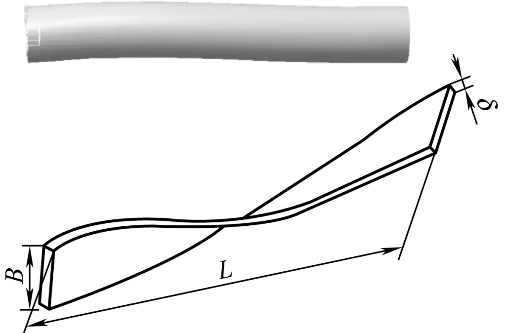
- Twisting deformation (see Figure 3).

a) Overall Bending Deformation of Channel Steel
b) Local Bending Deformation of Angle Steel
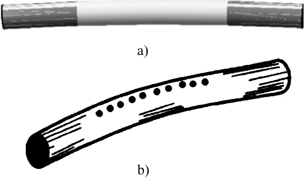
a) Single-direction Bending Deformation
b) Multi-directional Bending Deformation
2) Common Deformation Forms of Plates (see Figure 4)
Plate deformation forms are more complex, usually including middle bulge (commonly known as “bulge”), overall wave bending or twisting deformation, edge warping (usually wavy), and composite deformation.
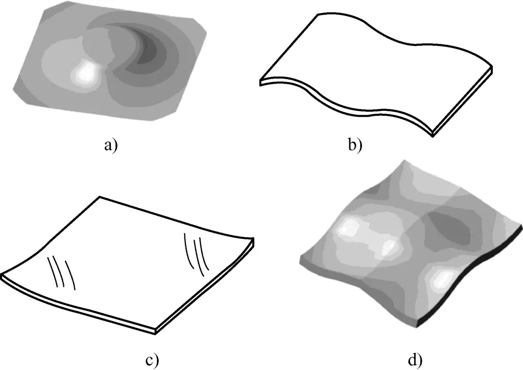
a) Middle Bulge Deformation
b) Plate Waveform Deformation
c) Edge Warping
d) Plate Composite Deformation
(2) Common Tools and Accessories for Correction
1) Common tools and accessories for manual correction are shown in Table 1.
Table 1 Common Tools and Accessories for Manual Correction
| Name | Illustration | Purpose | |
| Hammer | Ball-peen hammer | 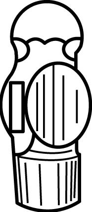 | Mainly used for correcting thick plates and shaped steel |
| Duckbill hammer | Mainly used for correcting thin plates | ||
| Wooden mallet | 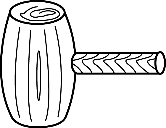 | Mainly used for correcting thin steel plates below 1mm and non-ferrous metal thin plates | |
| Octagonal hammer | 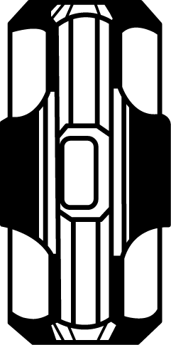 | Mainly used for large thickness and heavily deformed blank materials and heavily deformed types of shaped steel correction | |
| Correction jigs | Correction flat plate | 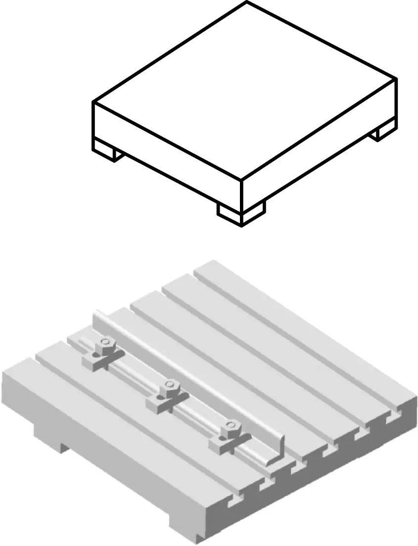 | Used for correcting workpieces, especially plates. T-slots can hold bolts for positioning and correcting workpieces. When correcting angle steel, you can fix one side as needed and hammer the other side |
| Anvil | 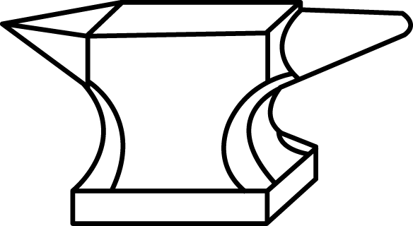 | Used for correcting small deformations of small workpieces | |
| Bending tools | 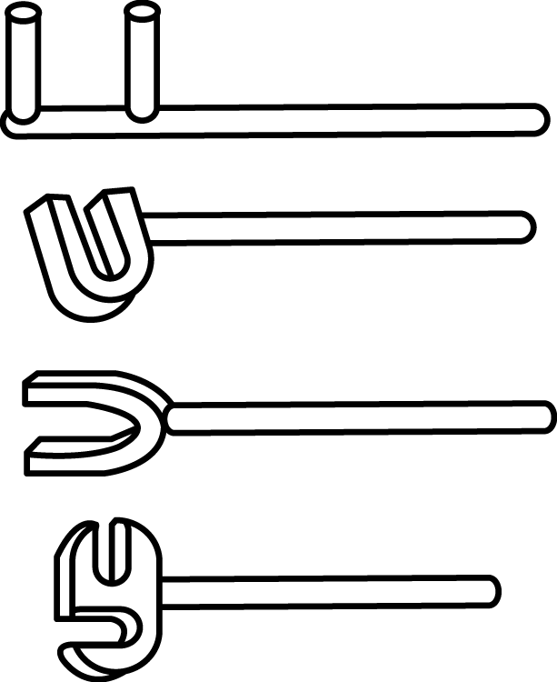 | Mainly used for manual bending corrections, such as cooperating with a vise to correct torsional deformation of strip material | |
| Straightener | 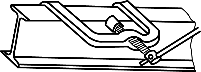 | Used for straightening horizontal bending deformation of I-beam flanges | |
2) Press
There are many types of presses, such as friction presses, crank presses, eccentric presses, and various hydraulic presses. Manual correction often uses a manual screw press (see Figure 5), which is simple in structure, easy to operate, and can be used to correct small deformations of strips and rods.

Deformation of thinner plates can be manually corrected, while bending deformations of thick plates usually use a steel plate straightening machine. However, if there is no steel plate straightening machine, a hydraulic press can also be used. Figure 6 shows the appearance of a commonly used hydraulic press, which mainly consists of a motor, hydraulic drive device, column, guide post, and work platform.
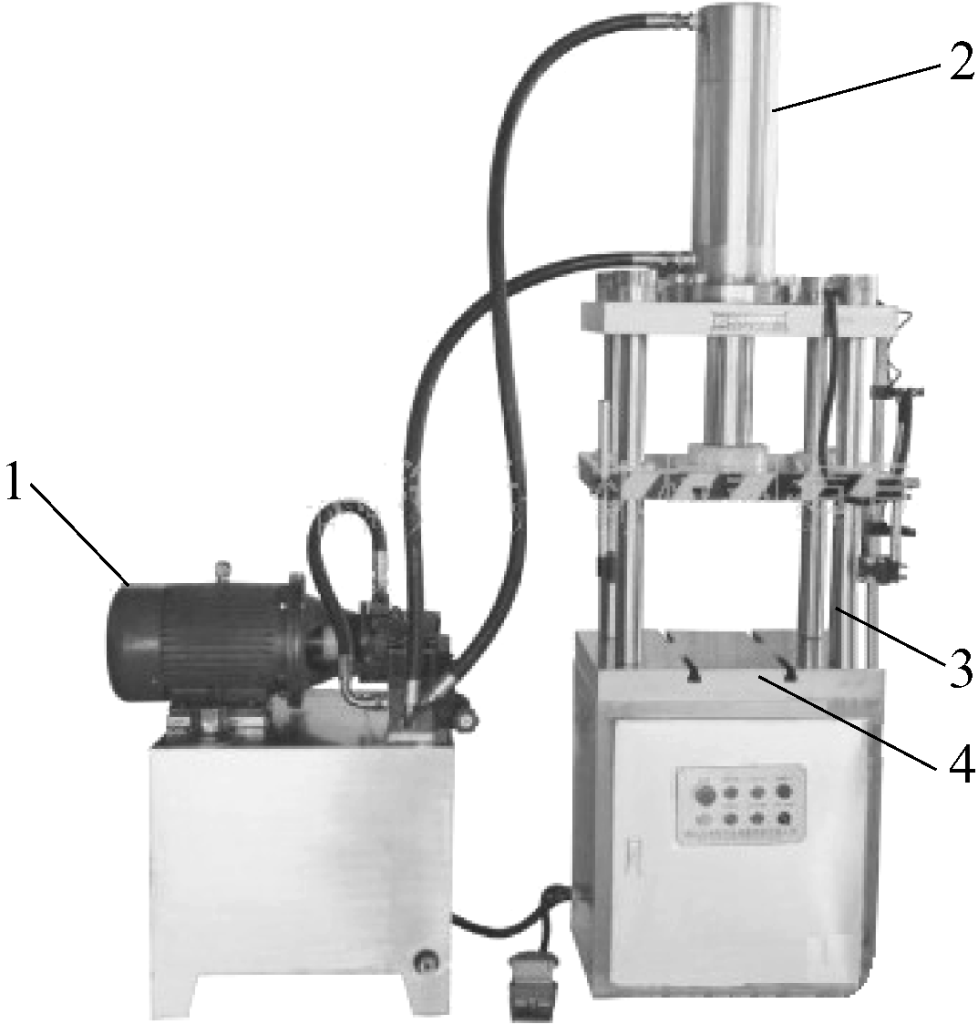
1—Motor
2—Hydraulic drive device
3—Guide post
4—Work platform
(3) Basic methods for correcting strips and plates
1) Basic Principles of Straightening Material Strips
The bent or twisted section of a strip is precisely where the metal material is densely combined, that is, the “tight” part. Therefore, the aim of straightening is to apply force with the appropriate tools to these parts to “loosen” them, achieving relative balance in material tightness, resulting in a flat state, which is the effect of straightening.
Cold straightening of material strips should be analyzed based on specific conditions such as cross-sectional shape, material thickness, and degree of deformation. The basic method for straightening individual material strips is discussed as follows:
① If there are both overall bending deformation and local bending deformation on the strip, local bending deformation should be corrected first, followed by the overall bending deformation.
② If there are multi-directional bending deformations in the strip, the amount of bending deformation should be detected from different directions. Usually, the side with a smaller amount of bending deformation is corrected first, followed by the side with a larger deformation amount.
For rectangular cross-section strips (such as flat steel), first, correct the bending in the vertical direction (width direction), then correct the bending in the horizontal direction (length direction); for angle steel or channel steel, correct the edge where the two faces intersect first, then correct the vertical face, and finally correct the horizontal face.
③ Correct torsional deformation before correcting bending deformation.
- First, detect the twisted section of the material strip and use the torsion method to correct it. The process involves clamping the strip in a vise and using a wrench to twist the strip back to its original shape (see Figure 7).
- For strips that have both torsional and bending deformation, generally, the torsional correction is done first, followed by bending correction.

④ Over-Correction Principle. To eliminate spring-back due to elastic deformation, when correcting bending deformation, pressure should be applied to the protruding parts, and some additional pressure should be exerted. When correcting torsional deformation, the twist angle should also be appropriately increased to eliminate spring-back.
2) Basic Leveling Methods for Sheet Materials
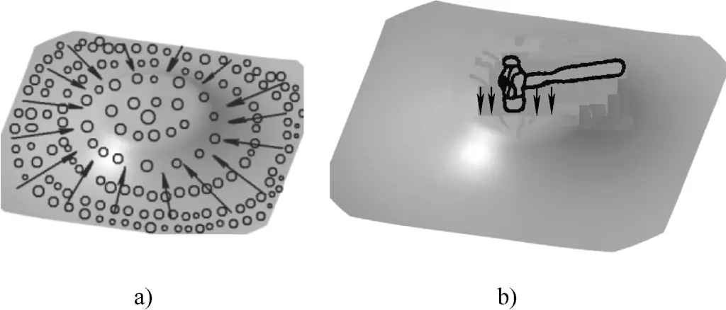
① Correction of convex parts in metal thin sheets. As shown in Figure 8, the convex in the thin sheet indicates that the material thickness in the center of the sheet has become thinner. Therefore, during the leveling operation, a hammer should be used to strike the sheet from the outside to the inside, from dense to sparse, and from heavy to light.
a) Correct Leveling Method
b) Incorrect Leveling Method
The arrows shown in Figure 8a indicate the direction of hammering. Only in this way can the material thickness of each part of the thin sheet be uniform, achieving the purpose of leveling. In Figure 8b, if the hammering force is applied to the already thinned convex position during leveling, it will only make the convex part thinner, worsening the deformation, hence constituting an incorrect leveling method.
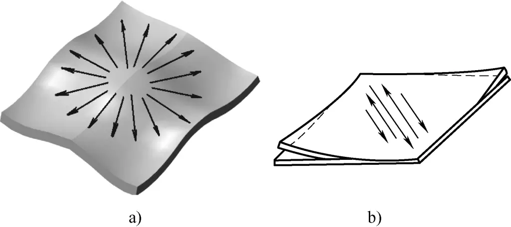
② Correction of metal thin sheets with wavy edges. For deformed sheets with wavy edges (edges thinned and lengthened), leveling should be done by hammering from inside to outside, from dense to sparse, and from heavy to light (arrows in Figure 9a indicate the hammering direction). The ultimate goal is to make the material thickness at the center of the sheet as thin as the edges, thereby achieving full sheet leveling through such ductile hammering.
a) Wavy Edges
b) Diagonal Warping
③ Correction of diagonally warped metal thin sheets. If diagonal warping occurs in thin sheets, hammer along the diagonal without warping to spread it out and level, as shown in Figure 9b.
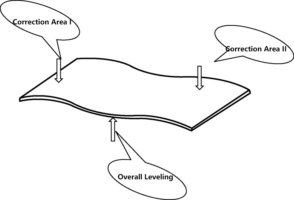
④ For sheets with an overall wavy shape, first, level the sections with smaller deformation, then use a press to roll for overall leveling, as shown in Figure 10.
⑤ For sheets with compound deformation, first correct warping, then level wavy edges, and finally level convex parts.
2. Basic Technology of Bending
(1) Principle of Bending
As shown in Figure 11, the closer the bent workpiece is to the material surface, the more severe the metal deformation, making cracking or crushing more likely. The degree of deformation in the outer layer of the bent workpiece depends on the bending radius. The smaller the bending radius, the greater the deformation of the outer layer (see Figure 11).
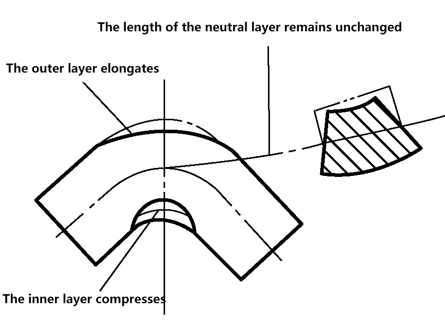
To prevent cracking (or crushing) of the bent part, it is necessary to limit the bending radius of the workpiece, making it greater than the critical bending radius that leads to material cracking (i.e., the minimum bending radius). If the bending radius of commonly used steel is greater than twice the material thickness, cracks generally do not occur.
After the workpiece is bent, the springback phenomenon causes the bending angle and radius to change due to elastic deformation. The workpiece should be bent slightly more to compensate for springback.
Common bending operations for strip material include flat bending, upright bending, and twist bending, as shown in Figure 12.
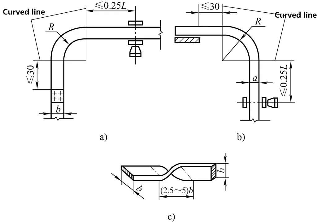
a) Flat bending
b) Upright bending
c) Twist bending
The common bending form for sheet material is flat bending, as shown in Figure 13.
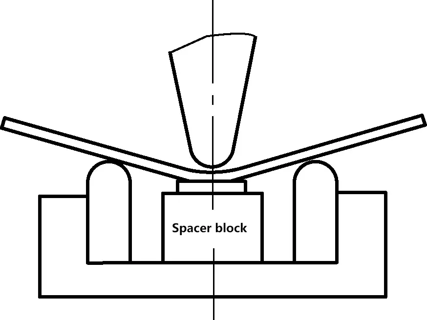
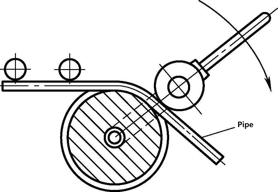
Pipe bending is shown in Figure 14.
(2) Calculation of the bent blank length
According to the concept of the neutral layer, the blank length should equal the length of the neutral layer.
As shown in Figure 15, the radius of the neutral layer arc after bending is
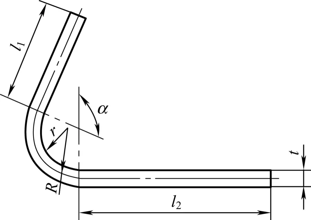
R=r+x0t
The arc length of the neutral layer after bending is
l=πRα/180°
= π(r+x0t)α/180°
In the formula, l is the arc length (mm); r is the inner bending radius (mm); x0 is the neutral layer position coefficient; t is the material thickness (mm); α is the bending angle.
The bending neutral layer position coefficients are shown in Table 2.
Table 2 Bending neutral layer position coefficients
| r/t | 0.25 | 0.5 | 0.8 | 1 | 2 | 3 | 4 | 5 | 6,7 | 8 | 10 | 12 | 14 | >16 |
| x0 | 0.2 | 0.25 | 0.3 | 0.35 | 0.37 | 0.4 | 0.41 | 0.43 | 0.44 | 0.45 | 0.46 | 0.47 | 0.48 | 0.49 |
(3) Common tools for bending operations
The aforementioned correction tools are also used for bending operations. Here is an introduction to some simple tools and basic equipment necessary for bending.
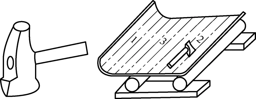
1) Arc hammer
As shown in Figure 16, when bending a curved surface, the arc hammer is always pressed along the meridian line of the cylindrical surface in a staggered manner to ensure that there are no straight segments at the end of the plate material, resulting in better forming and a smooth surface.
2) Common clamping tools for bending
In bending, the spiral clamp is mainly used to secure the workpiece to be bent, facilitating the application of external force. Pneumatic and hydraulic clamps serve the same purpose, as shown in Figure 17.
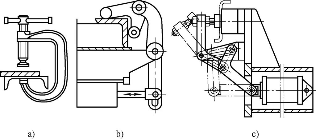
a) Spiral clamp
b) Pneumatic clamp
c) Hydraulic clamp
3) Mechanical simple bending tools
① Figure 18 shows a homemade manual bending tool composed of a base plate, turntables, and handles. Grooves machined according to the workpiece thickness are present around the circumference of the two turntables, with the fixed turntable’s diameter matching the bending arc. To use it, insert the workpiece into the grooves of the two turntables and move the movable turntable to achieve the desired bending shape.

② Figure 19 shows another homemade manual bending tool. For bending, place the section of the plate (or strip) to be bent into the lifting machine’s clamping plate, attach the elbow, tighten the clamping plate screw, correct the front, back, left, and right positions, and then use the jack (usually a hydraulic jack) to bend the plate (or strip).

1, 9—Angle iron
2, 10—Stop head
3, 12—Clamping plate
4, 11—Plate (strip) material
5, 13—Elbow
6, 14—Jack
7, 8—Channel steel
15—Clamping plate screw
The bending angle can be corrected using an angle template. If the required angle is not achieved, continue the bending operation until the desired angle is reached.
It is relatively difficult for a fitter to bend sheet metal manually; nowadays, mechanical bending tools (both homemade and commercial models) are often used for vertical bending operations, as shown in Figure 20.
Figure 20a is a structural schematic of a mechanical bending tool, and Figure 20b is a photo of its commercial model. The structural principle and usage method are as follows:
Before bending, place the workpiece on the bending mold base. When bending, under the action of external hydraulic power, the piston rod drives the bending mold to press down, bending the workpiece to the desired angle. By replacing different bending molds and reasonably placing the bending pin position, different bending radii can be achieved.
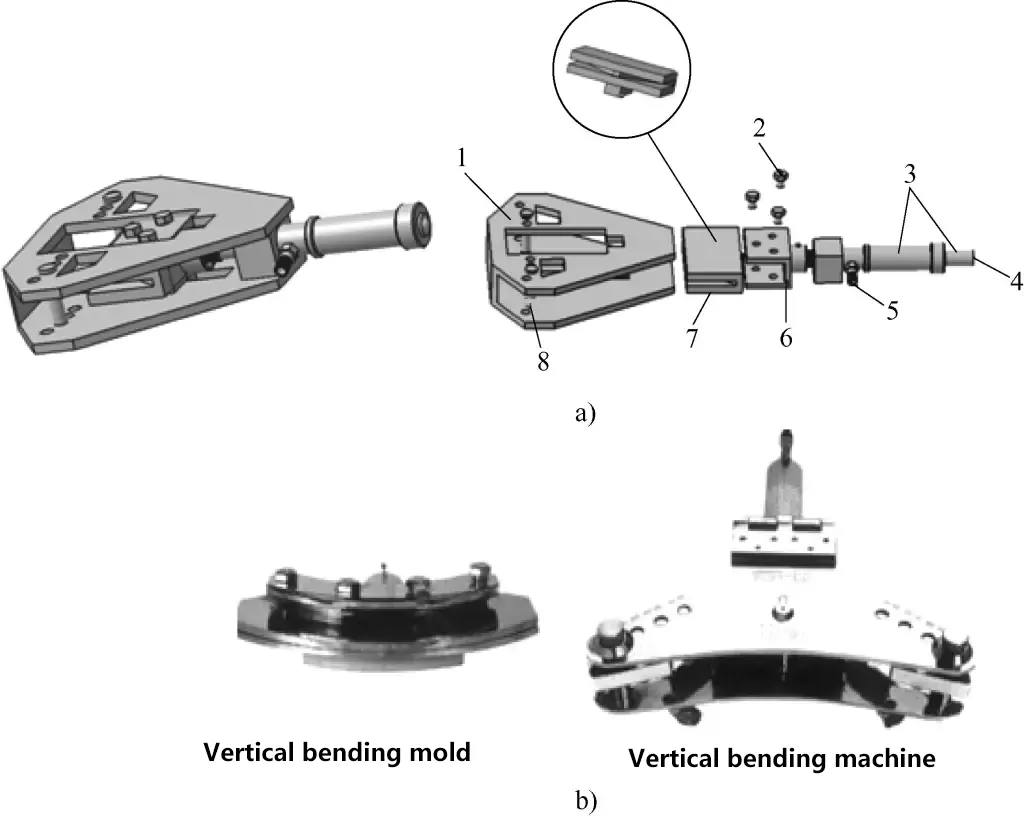
b) Mechanical Vertical Bending Mold Real Object
1—Vertical Bending Mold Base
2—Fastening Bolt
3—Hydraulic Cylinder and Piston
4—Connect to External Hydraulic Control Circuit
5—Hydraulic Pipe Joint
6—Bending Mold Base
7—Bending Mold
8—Bending Pin
4) Torsion Bender
As shown in Figure 21, during torsional bending, one end of the workpiece to be bent is clamped in a vice. To avoid damaging the workpiece with the jaws, an aluminum plate or hardwood should be placed between the jaws and the workpiece. The other end of the workpiece is clamped with a torsion bender, then both hands are used to forcefully rotate the handle of the torsion bender until the workpiece bends into the desired shape. When twisting 90°, the length of the twisted section should be no less than 2.5 times the width of the strip material.
5) Pipe Bender
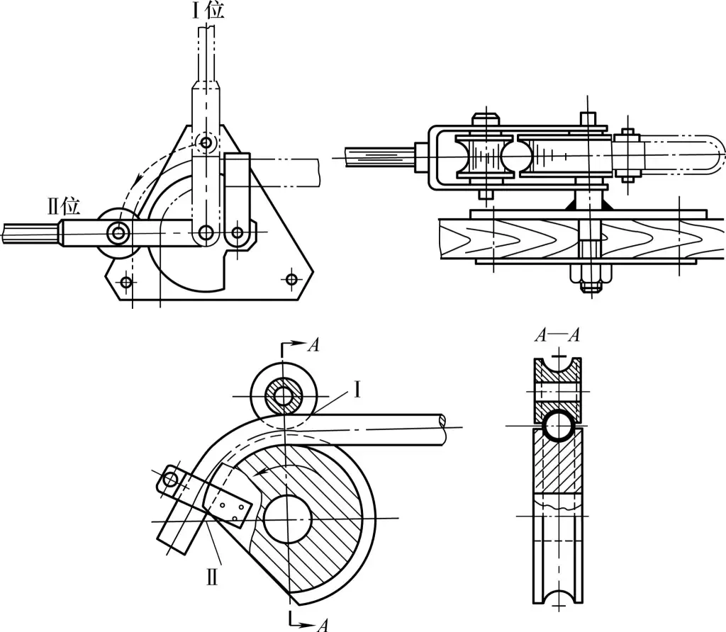
Figure 22a illustrates the working principle of the pipe bender. It consists of two wheels, one large and one small, which are equipped with grooves corresponding to the pipe diameter. The pipe to be bent is fed into the wheel grooves, the large wheel is fixed, and by pulling the lever, the small wheel presses the pipe to bend it into shape.
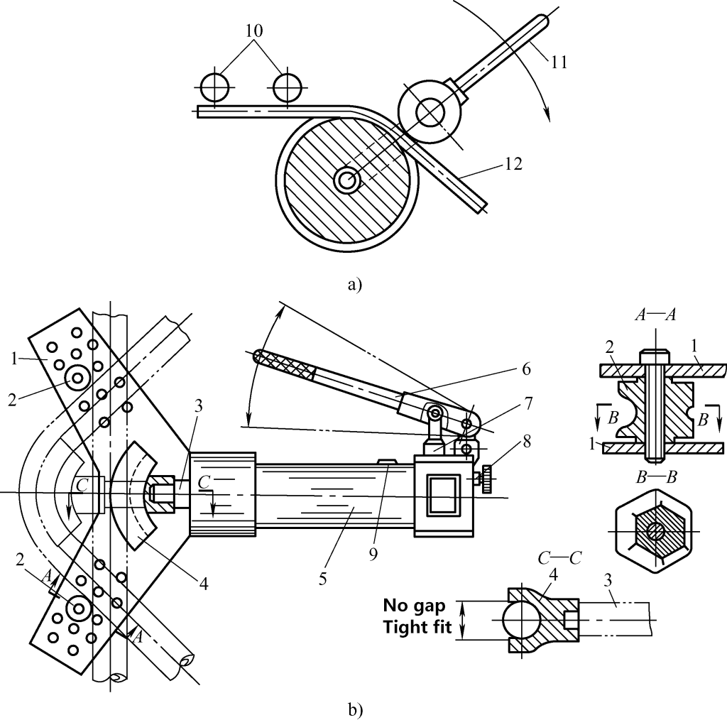
a) Pipe Bender Principle Diagram
b) Hydraulic Pipe Bender
1—Positioning Plate
2—Limit Guide Module
3—Working Piston Rod
4—Bending Mold of Different Specs
5—Machine Body
6—Hand Lever
7—Plunger-Type Oil Pump
8—Working Cylinder Return Valve
9—Fueling Screw Hole
10—Guide Roller
11—Lever
12—Pipe
Figure 22b shows the structure of the manual hydraulic pipe bender. Its main feature is the ability to bend pipes of different diameters by changing the model of the pipe bending die.
6) Press machine and bending die
As shown in Figure 23, for thicker plates, manual bending is difficult. Different types of dies are usually installed on the press to mechanically drive the bending of plates into various shapes.
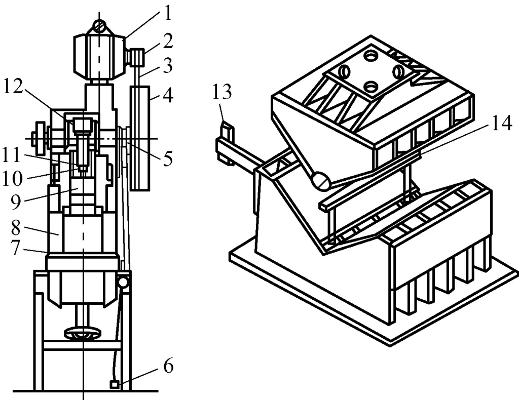
1—Motor
2—Reduction Pulley
3—Drive Belt
4—Flywheel
5—Clutch
6—Foot Pedal Control System
7—Table
8—Bed
9—Slider
10—Linkage
11—Slider Guide Rail
12—Crankshaft
13—Positioning Baffle
14—Support Plate
7) Bending Press
The bending press is mainly used for bending sheet metal, as shown in Figure 24a. The bending dies used on the bending press can be divided into general bending dies and special bending dies. The common end profile of the general bending die is shown in Figure 24b.
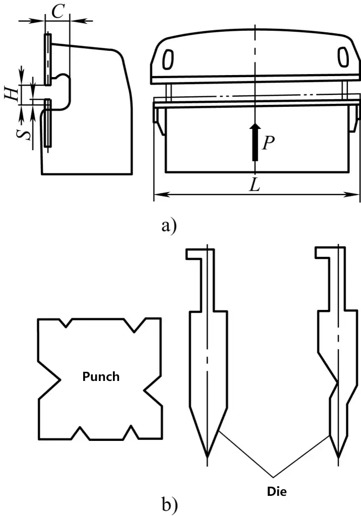
a) Bending Press
b) General Bending Die for Bending Machine
II. Basic Operational Skills
1. Correction Methods for Various Types of Material
(1) Manual Correction of Square Bars
1) Correction of the thickness direction of strip material
① Manual hammering correction method
For smaller strip materials, correction can be divided into initial and final processes. During initial correction, the strip can be clamped in a bench vise and hammered. Once the bending degree is reduced, place the strip on a flat plate for straightening. Note that during hammering, the impact points should be along the strip’s longitudinal centerline to avoid lateral bending, as shown in Figure 25.
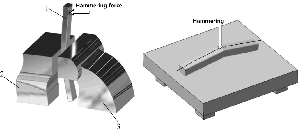
1—Bent flat steel
2—Fixed vise body
3—Adjustable vise body
② Straightening machine correction
Strip materials with larger bending deformations can be straightened using a straightening machine, as shown in Figure 26.

1—Base
2—Rod material
3—Strip material
Before correction, first support the workpiece on two support irons (use V-shaped iron for shafts; use channel steel for strips). The distance between the support irons can be adjusted as needed. Mark the bent area with chalk, then rotate the screw of the screw press to press the block onto the protruding part of the workpiece.
To eliminate springback caused by elastic deformation, slightly over-press. Then, check the correction using a steel ruler (if requirements are not strict) or a dial gauge. Check as you correct until it meets the requirements.
2) Correction of the width direction of square strip material
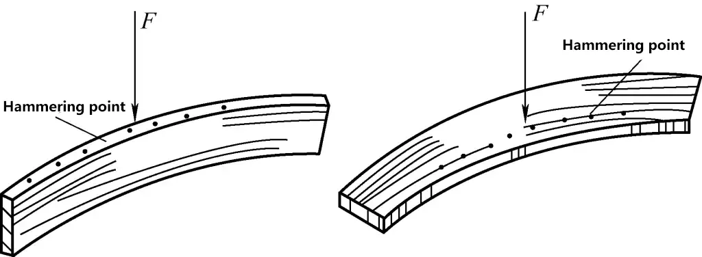
As shown in Figure 27, the correction for deformations in the width direction can be done by directly hammering the raised part or hammering the edges of the concave part to allow the “compressed” material to expand and “release” on both sides. Ensure the hammering is even until the flat steel is straightened.
3) Correction of twisting deformation of square strip material
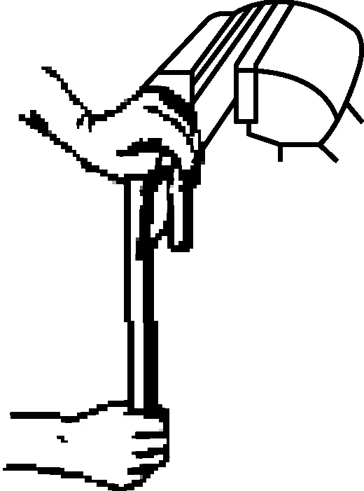
As shown in Figure 28, if the strip material has become twisted, the twisting method can be used for correction. Clamp the strip in a bench vise and use a wrench to twist the strip back to its original shape.
(2) Manual correction of angle steel
1) Correction of angle steel angle deformation
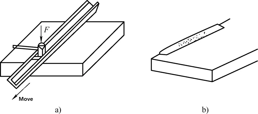
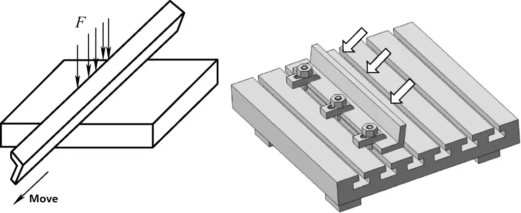
① If the angle of the angle steel is less than 90° and the angle change is small, the correction method shown in Figure 29 can be used: Place the angle steel with the opening facing down on a flat plate, use a hammer along the rib of the angle steel, or use the methods shown in Figure 30a, 30b, moving the angle steel while hammering the inner surface.
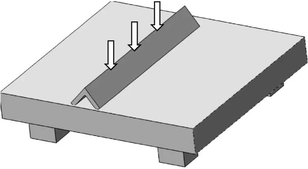
After angle correction, place the inner surface of the angle steel closely against two adjacent sides of a flat plate and hammer the outer surface of the angle steel to eliminate slight inner bending caused by angle correction. If the angle change is significant, a press can be used for correction, similar to the method for correcting strip material with a press.
② If the angle of the angle steel is greater than 90°, the correction method shown in Figure 31 can be used.
Place the angle steel on a flat plate with one edge touching the plate. Move the angle steel while hammering along the edge of the opposite side. Another method is to fix the angle steel on the flat plate and hammer the unfixed side’s outer surface.
2) Correction of external and internal bending of angle steel
① Correction of external bending deformation of angle steel
As shown in Figure 32a, support the externally bent angle steel on a flat plate with two spacers and hammer the upper edge. Start hammering from the highest point of the protruding part on the upper edge and expand outward from heavy to light. After hammering, the inner surface of the angle steel will gradually straighten along with the edge.
Once the warping is mostly eliminated, further straighten the slightly bent surface with a hammer until the angle steel is corrected. Incorrect correction methods are shown in Figure 32b.
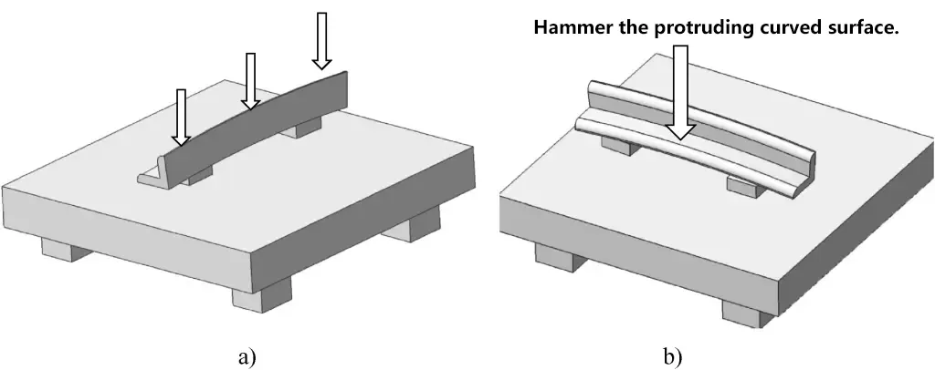
a) Correct method for correcting external bending deformation of angle steel
b) Incorrect method for correcting external bending deformation of angle steel
② Correction of internal bending deformation of angle steel
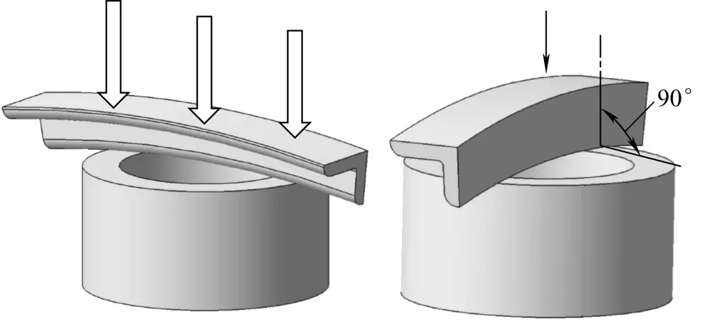
As shown in Figure 33, when correcting internal bending deformation, place the concave side on a hollow barrel and hammer from the highest point of the protruding part outward, from heavy to light. The outer surface of the angle steel will gradually become straight.
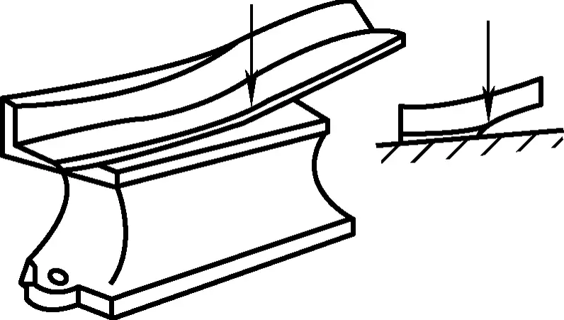
However, ensure that one edge in contact with the anvil is perpendicular to the anvil surface. This way, the angle steel won’t tilt during hammering, which would affect the result.
3) Correction of twisted deformation of angle steel
Method one: As shown in Figure 34, place the twisted angle steel on an anvil and hammer the inside of the twisted part to extend it. After correcting the twist, correct the internal bending as previously described.
Method two: Alternatively, use the previously mentioned method for correcting twisted strips. Clamp the angle steel in a vise and use a lever to twist both sides separately to eliminate the overall twist, then correct the internal bending.
2. Common bending methods and examples
Before bending, first calculate the blanking length of the material that needs bending based on the dimensions on the drawing and mark the bending line correctly. The common workpiece bending process is as follows:
(1) Manual single right-angle bending
When the size of the sheet or strip material is small and quality requirements are not high, manual bending can be used. Figure 35 shows an example of a fitter performing a bending operation on a vise.
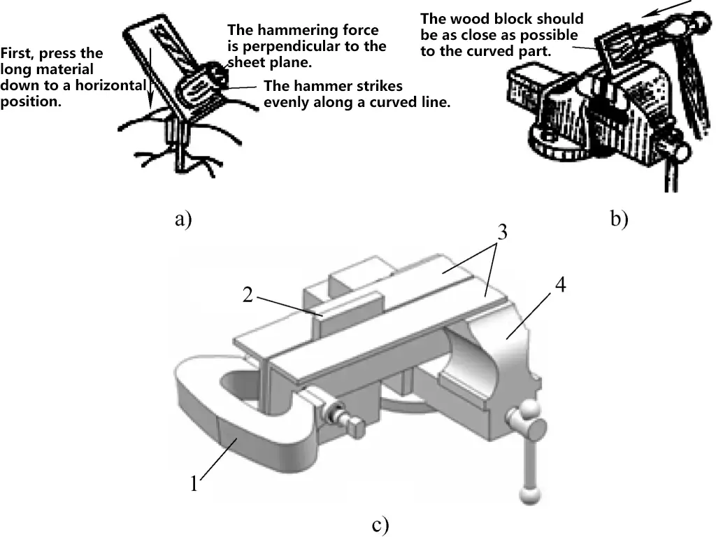
a) Bending method when the part above the bending line is longer
b) Bending method when the part above the bending line is shorter
c) Bending method when the vise jaws are shorter or not deep enough for the workpiece
1—Chuck
2—Sheet material
3—Angle iron
4—Vise
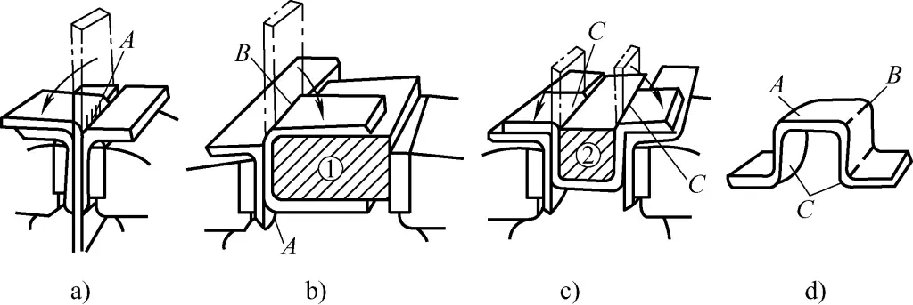
(2) Four right-angle manual bending
When bending a four right-angle workpiece, wooden or metal blocks can be used as auxiliary tools. As shown in Figure 36, the bending sequence is as follows: first, clamp the sheet material with the marked line into the angle iron and bend into angle A (see Figure 36a), then use block ① to bend into angle B (see Figure 36b), and finally use block ② to bend into angle C (see Figure 36c).
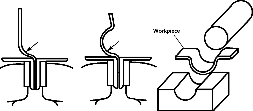
(3) Arc-shaped Workpiece Bending
As shown in Figure 37, mark the bending line on the workpiece, use the narrow head of the square head hammer to hit the area to be bent, then switch the hammer to shape it roughly, and finally shape it on a concave mold.
(4) Cylinder-shaped Workpiece Bending Process
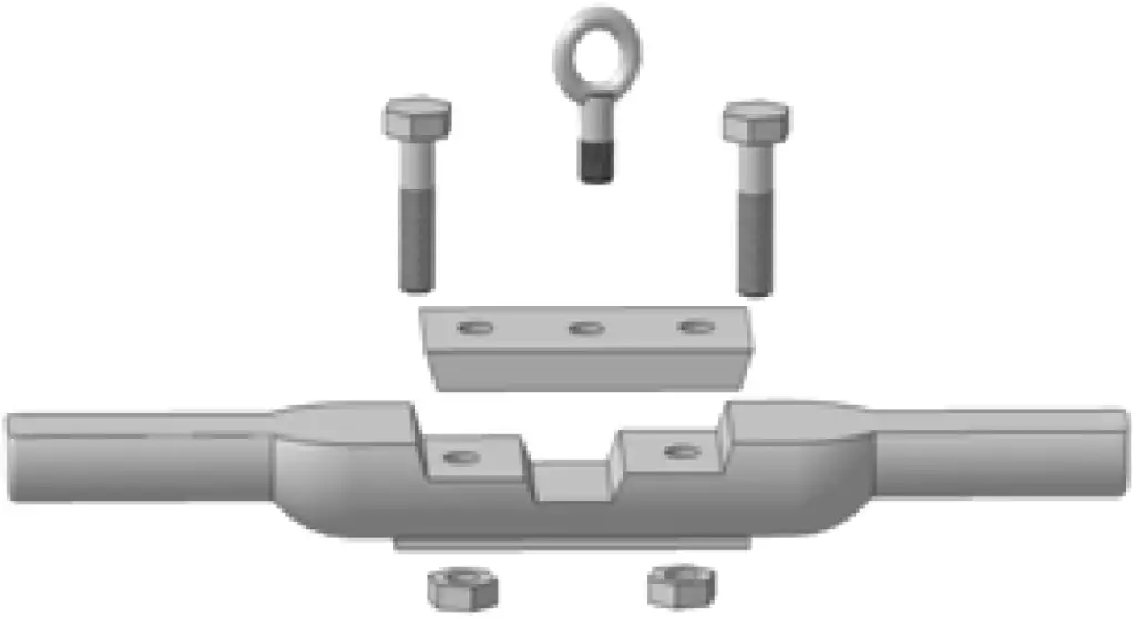
Figure 38 shows the common clamp jig shape, with the following bending process steps:
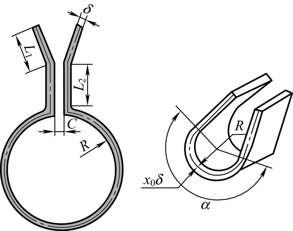
1) Calculate the blank cutting length, i.e.
L=L1+L2+C+πα/180°(R+x0δ)
2) As shown in Figure 39, chisel or saw to cut the material, then drill and chamfer. Mark the bending line and arc surface bending division line (to facilitate arc hammer bending).
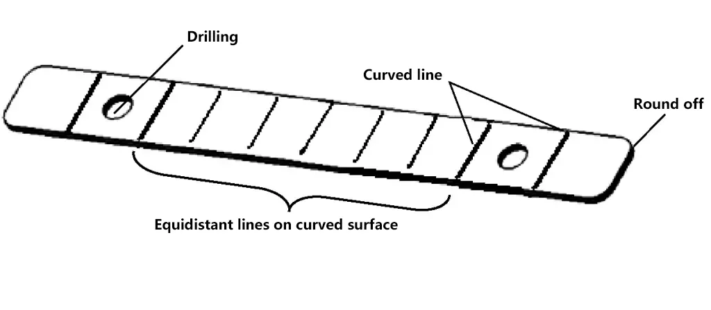
3) Bend the L1 part and L2 part on a vise.
4) As shown in Figure 40, use a vise to clamp cylindrical rod material, bend two small arcs at both ends of the blank plate (less than 1/4 of the inner arc of the clamp).
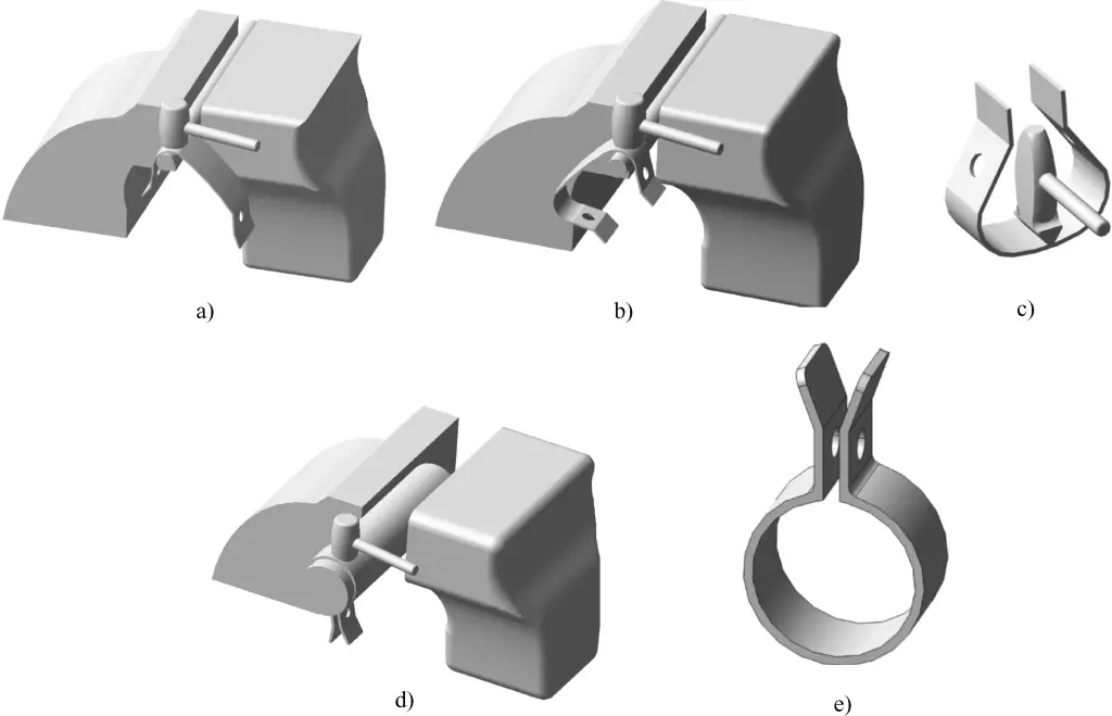
5) As shown in Figure 40c, use an arc hammer to strike out an approximate arc surface according to the arc surface bending division line.
6) As shown in Figure 40d, clamp a rod or pipe (diameter slightly smaller than the clamp diameter) in a vise as a mold for fine-tuning the clamp arc surface, and fit the roughly shaped inner arc surface to the cylindrical rod, using a hammer along the rod’s arc surface to fine-tune the clamp arc surface contour.
(5) Manual Pipe Bending Process
Manual pipe bending is divided into cold bending and hot bending methods; pipes with a diameter below ϕ10mm can be cold bent; pipes with a diameter greater than ϕ10mm should be bent hot to prevent flattening or cracking after bending.
Generally, the pipe should be filled with dry sand for bending; for cold bending, the bend radius should be greater than 3 times the pipe’s outer diameter; for hot bending, the bend radius should be greater than 4 times the pipe’s outer diameter. When bending pipes with weld seams, the seam must be placed in the neutral layer.
1) When marking, determine the midpoint of the bending area according to the drawing dimensions.
2) Before hot bending the pipe, calculate the heating length of the pipe, as per the previous formula and Figure 41.
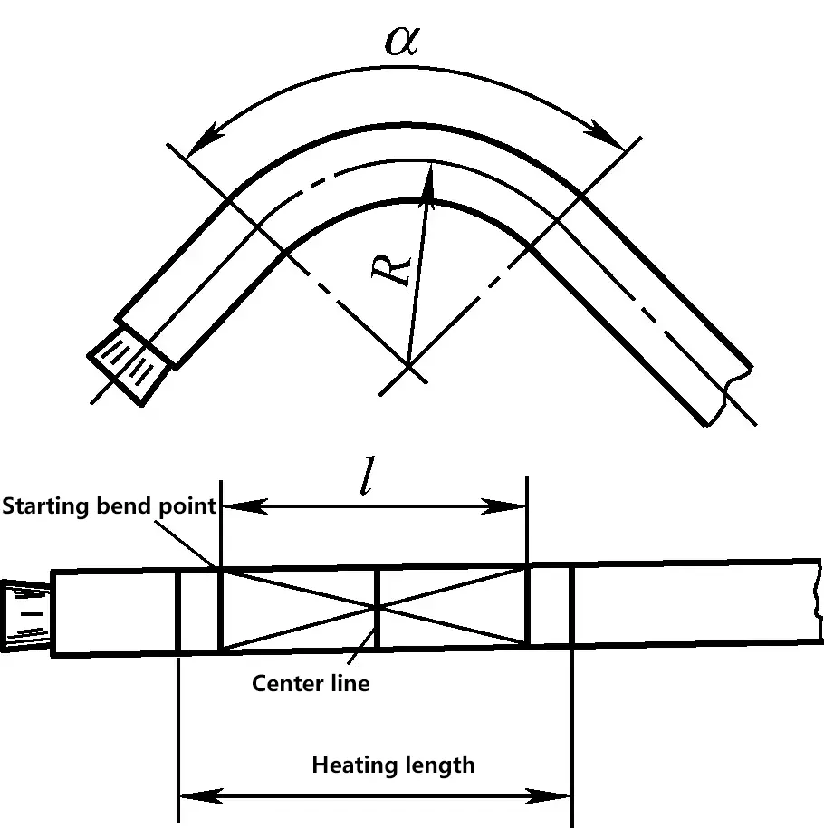
The heating length of the pipe is
l=πRα/180°
3) Generally, coke furnaces are used for heating; for pipes with an outer diameter below ϕ15mm, the heating temperature is about 850℃; for pipes with an outer diameter above ϕ15mm, the heating temperature is 950~980℃. Heating should be slow and uniform. Upon reaching the specified temperature, perform short-term heat preservation to ensure the pipe and dry sand temperatures are roughly consistent.
4) Pipe bending process. As shown in Figure 42, first retract the pry bar to position I, insert the pipe into the mold hole formed by the moving wheel and the fixed wheel, then exert force on the pry bar, bending from position I to II, bending the pipe to the required angle, and then return from position II to I.
3. Causes of Scrap in Bending and Preventive Measures (See Table 3)
Table 3 Causes of Scrap in Bending and Prevention
| Bending Defects | Causes | Preventive Measures |
| Fracture of Workpiece During Bending | 1) Poor plasticity of workpiece material; 2) Repeated bending multiple times; 3) Bend radius is too small; 4) Improper selection of bending location | 1) Correctly select billet with sufficient plasticity; 2) Follow bending procedure to minimize bending frequency; 3) Verify the minimum bend radius of the workpiece; 4) Correctly choose bending position and properly mark the bend line |
| Excessive Shape and Size Errors After Bending | 1) Error in calculating blank size; 2) Incorrect or insecure workpiece clamping position; 3) Incorrect mold selection; 4) Excessive bending force or oblique force application | 1) Accurately calculate pre-bend blank size to avoid large errors; 2) Choose the correct clamping position and ensure strong clamping without deforming the blank; 3) Verify mold shape and size to prevent incorrect mold selection; 4) Apply bending pressure step by step according to procedure and prevent oblique force application |
| Indentation or Cracking of the Pipe After Bending | 1) Weld seam not placed at neutral axis; 2) Bend radius too small; 3) Sand not filled or compacted inside the pipe during hot bending | 1) Place weld seam at the neutral axis during bending; 2) Select minimum bend radius as specified; 3) Use sand to firmly fill the pipe during hot bending and try to bend in one go |

