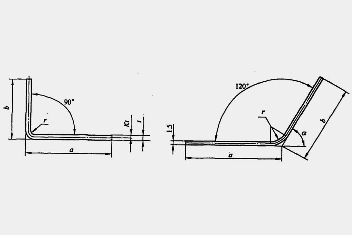
Guide to Calculating Unfolded Dimensions for Sheet Metal Bending
Have you ever wondered how to achieve precise dimensions in sheet metal bending? This article delves into the essential techniques…
What determines the bending force needed to shape metal accurately? Understanding these forces is crucial in selecting the right presses and designing effective molds. This article dives into the essential formulas for calculating bending force, considering various bending methods and material properties. Learn how to apply these calculations to achieve precise bends, enhancing the quality and efficiency of your metalworking projects.
Bending force is an important basis for designing stamping processes, selecting presses, and designing molds.
Since the magnitude of the bending force is related not only to the size of the blank, the mechanical properties of the material, the distance between the supports of the die, the bending radius, and the clearance between the molds, but also greatly related to the bending method, it is difficult to perform accurate calculations using theoretical analysis methods. Therefore, in production, the empirical formulas listed in Table 1 are usually used for a rough calculation of the bending force.
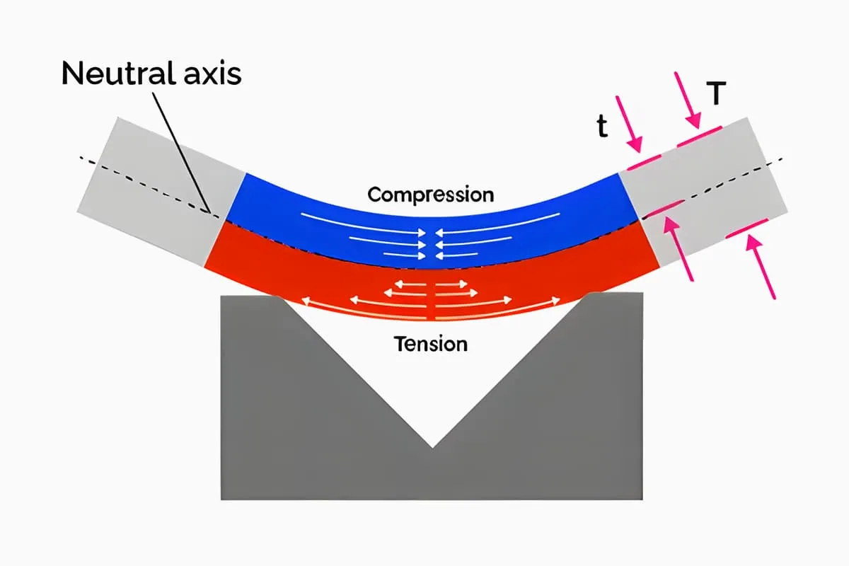
The theoretical calculation method of bending force is derived under the static equilibrium conditions that the sum of various external forces acting on the bending blank is zero, and the external torque acting on the bending blank is equal to its internal resistance torque, through conventional calculation.
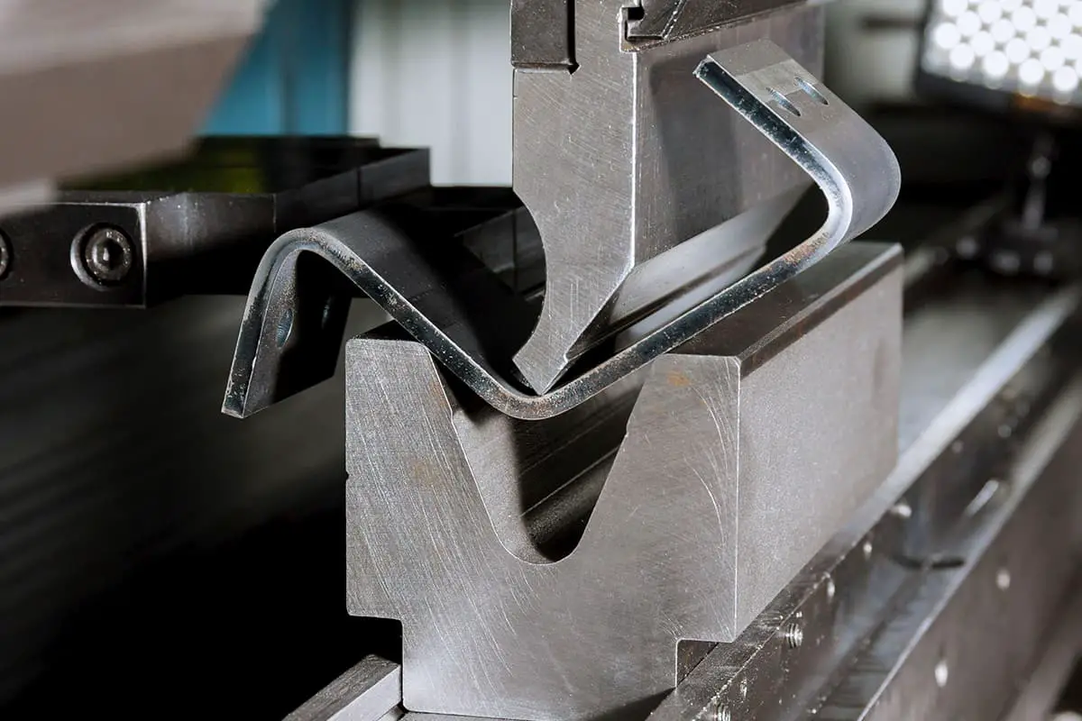
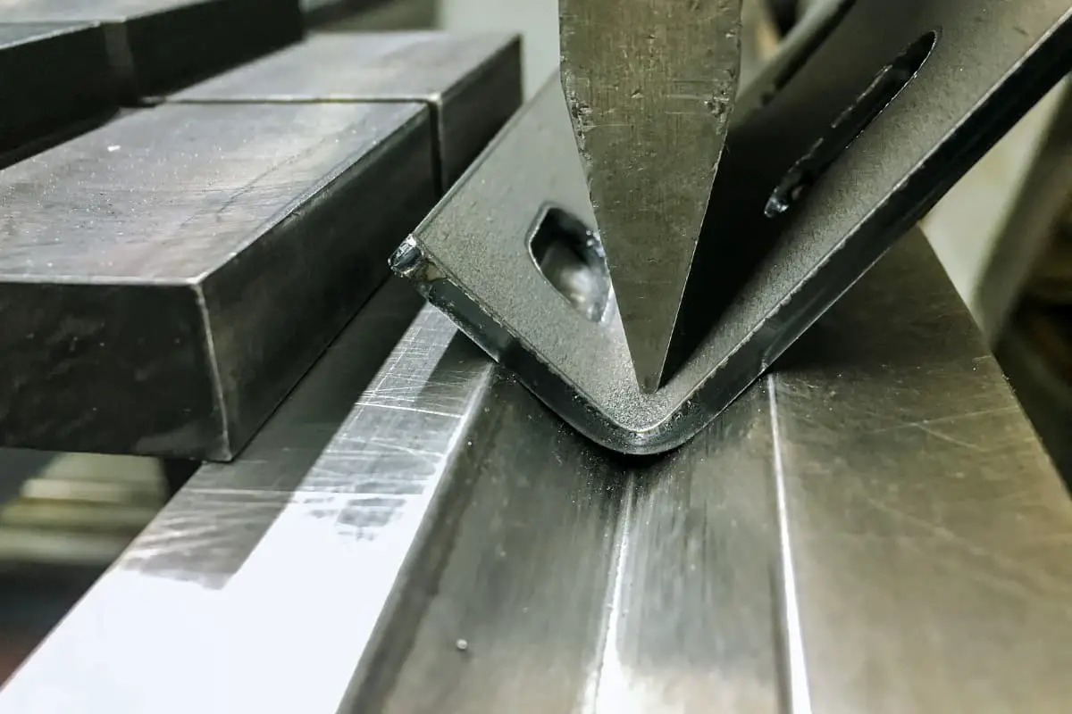
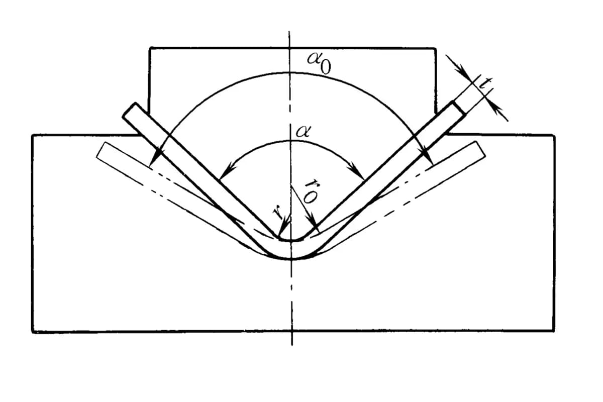
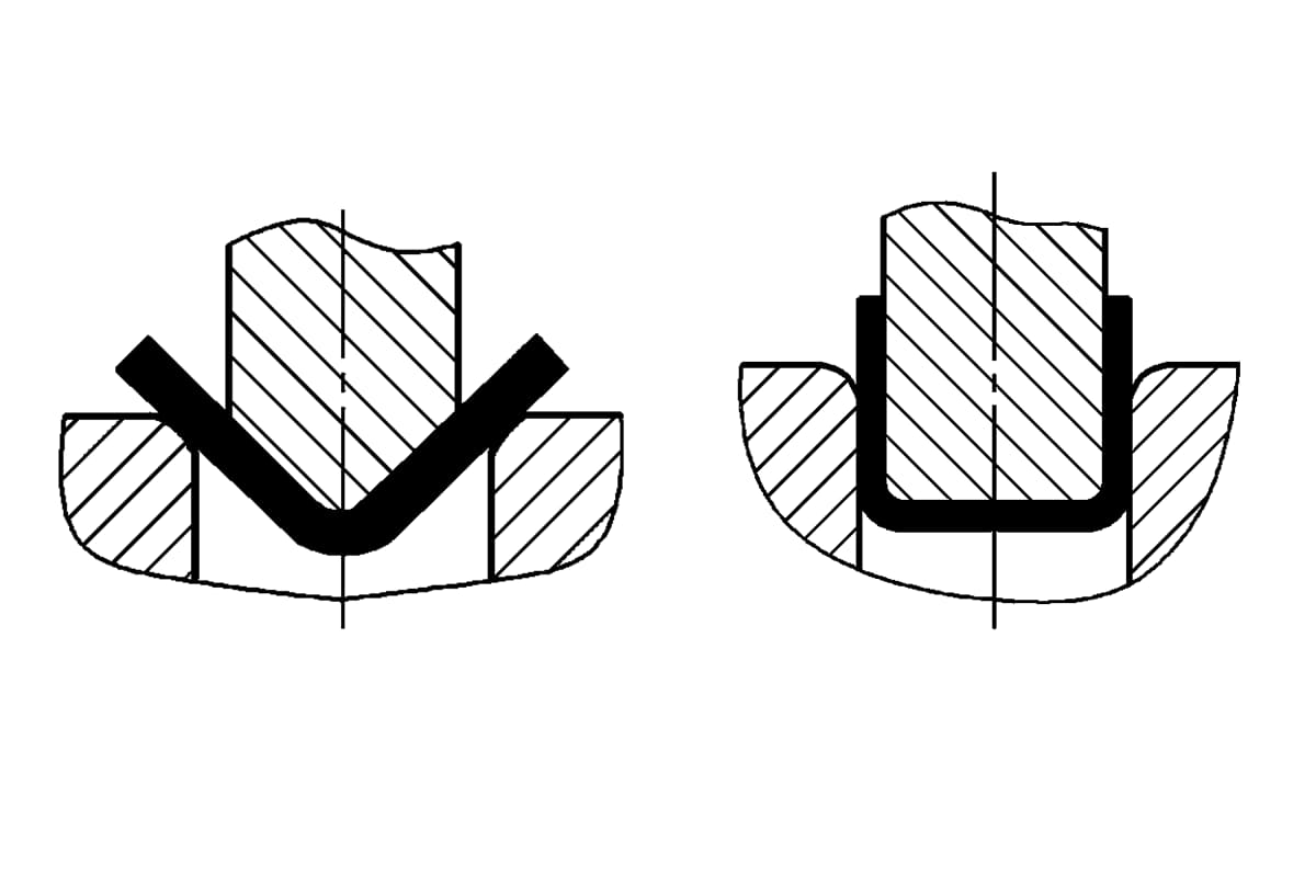
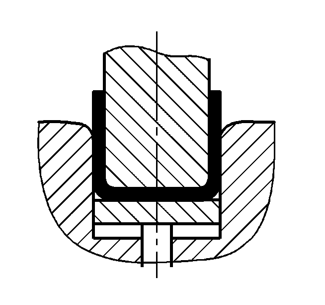
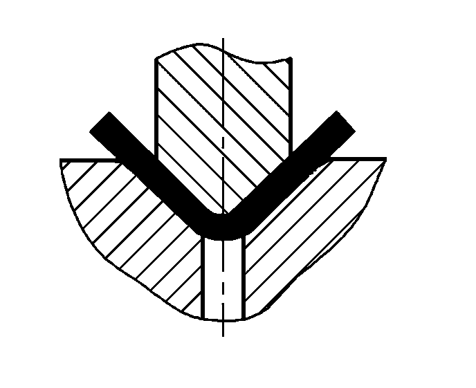
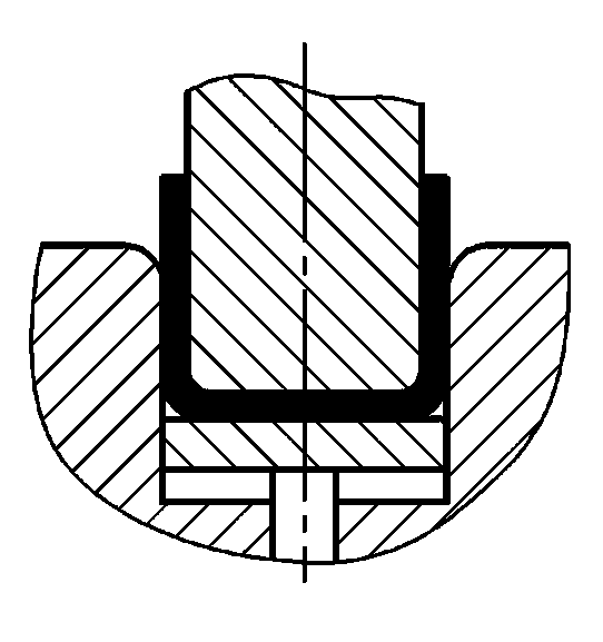
The bending method and die structure will change the stress state of the bending blank. Different bending methods result in vastly different bending pressures. Taking the commonly used V-shaped and U-shaped bending parts as examples, as shown in Figure 1, they can be formed by bending with ordinary full-steel bending dies, respectively using free bending, contact upsetting bending, and impact correction bending.
V-shaped bending parts use a concentrated load in the middle of two supports of a flat blank for pure bending and free bending, mostly used on construction sites. Online, small and medium-sized sheet metal bending parts are mostly formed by contact upsetting bending, and high-strength medium-thick plate bending parts are often bent on friction presses using impact correction bending. Free bending requires less pressure, with no additional pressure, only simple bending force.
The calculation formulas for bending force by various bending methods are shown in Table 1.
Table 1 Calculation formulas for bending force by various bending methods
| Name | Schematic | Characteristics of bending deformation | Bending force calculation formula | ||
| Theoretical | Approximate | Recommended | |||
| Single angle free bending (V-shaped bending part) | 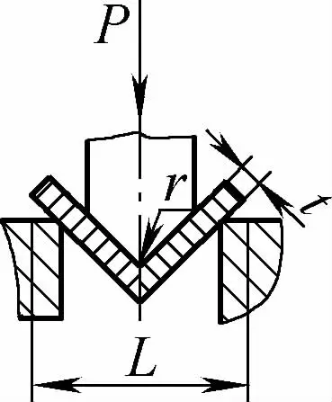 | The blank is bent down in the middle by applying pressure on two supports at the die entrance, the lower part does not contact the mold | When 2r≤L, F=0.7bt3 Rm /(r+t) When 2r>L, F=2bt2 Rm /3L | F = KbtRm | F=Cbt2Rm/L |
| Single-angle contact bending (V-shaped bending parts) | 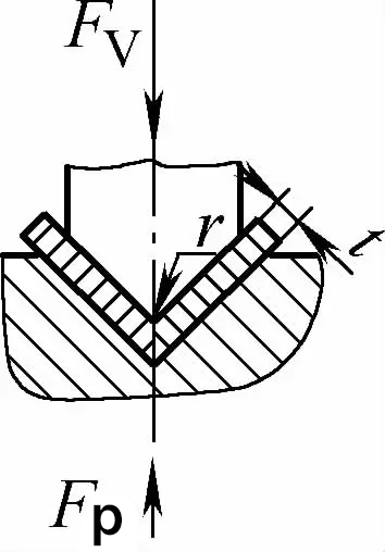 | Before the bending process is completed, the bending blank is in close contact with the entire mold cavity. A pressure plate is generally used to make the bending die gap greater than or equal to t | When 2r≤L, Fv =0.7bt2 Rm /(r+t)+Fp When 2r>L, Fv =2bt2 Rm /3L+Fp | Fv=KbtRm +Fp | Fv=2Cbt2Rm/L |
| Single-angle contact with impact correction bending (V-shaped bending parts) | 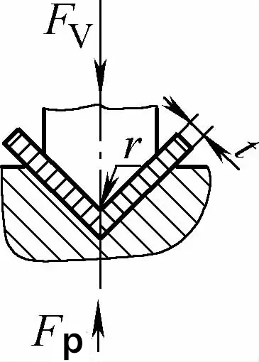 | Based on contact bending, it also has the function of impact correction. The bending die gap is generally less than or equal to t | Fv=0.7bt2Rm/L+Fp+qAb | Fv=1.3qAb | Fv=1.39qAb |
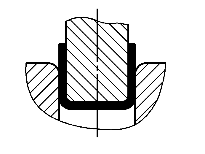
| Double-angle free bending (U-shaped bending parts) | 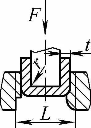 | The bending blank is bent in the middle by applying pressure on two supports at the die entrance, the lower part of the blank does not contact the mold | When 2r≤L, F=0.7bt 2 Rm /(r+t) When 2r>L, F=2bt 2 Rm /3L | F =KbtRm | F=0.4CKbtRm |
| Double-angle contact bending (U-shaped bending parts) | 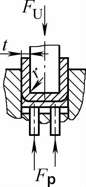 | During bending, a pressure plate is used or a gap equal to or slightly greater than t is used, but there is no impact correction function | When 2r≤L, Fu =0.7bt2Rm /(r+t)+Fp When 2r>L, Fu =2bt2Rmn/3L+Fp | Fu =KbtRm +Fp | Fu=0.5CbtRm |
| Double-angle contact with impact correction bending (U-shaped bending parts) | 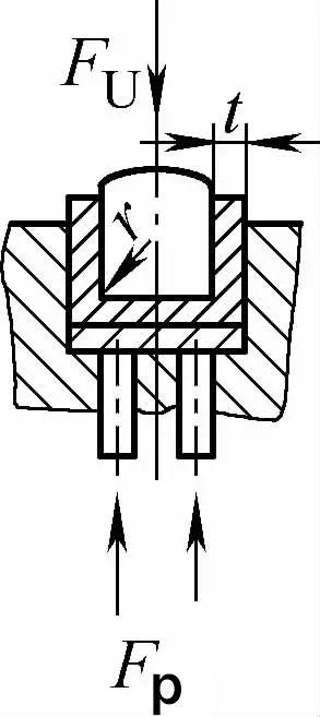 | During bending, a bending gap less than or equal to t is used with a pressure plate (top plate) and also has the function of impact correction | Fu=0.7bt2Rmn/L+Fp+qAb | Fu=1.3qAb | Fu=1.3qAb |
Note: The meanings of the symbols in the table are as follows:
Table 2 Material type coefficient K value
| Material | Ratio L/t | |||||
| 3 | 10 | 15 | 20 | 25 | 30 | |
| 10 steel, 15 steel, brass, aluminum (soft) | 0.23 | 0.18 | 0.12 | 0.09 | 0.073 | 0.060 |
| 20 steel, 25 steel, hardened aluminum | 0.21 | 0.17 | 0.11 | 0.08 | 0.070 | 0.057 |
| 20 steel, 25 steel, 40 steel, super-hard aluminum | 0.20 | 0.16 | 0.10 | 0.08 | 0.065 | 0.053 |
Table 3 Approximate value of unit (impact) correction pressure q during bending (unit: MPa)
| Material | Bending material thickness t/mm | |
| ≤3 | >3~10 | |
| Aluminum | 30~40 | 50~60 |
| Brass | 60~80 | 80~100 |
| 10 steel, 15 steel, 20 steel | 80~100 | 100~120 |
| 25 steel, 30 steel, 35 steel | 100~120 | 120~150 |
Formulas for calculating bending force
Table 4 Empirical formulas for calculating bending force
| Bending method | Schematic | Empirical formulas | Notes |
| Free bending | 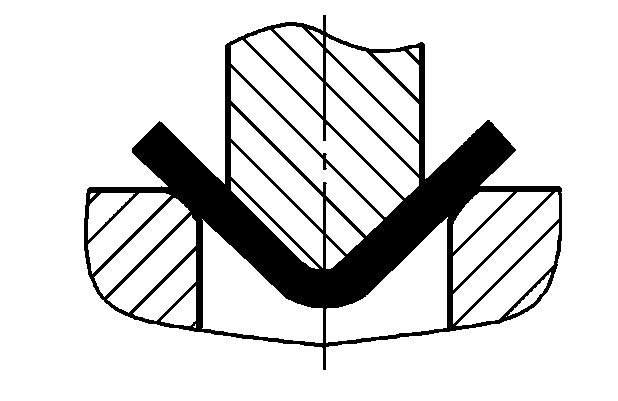 | P=(0.8Bt2σb)/(r+t) | where P-Total bending force (N) B-Width of the bent part (mm) t-Material thickness (mm) σb-Tensile strength (MPa) r-Inner bending radius (mm) A-Correction part projection area (mm2 ) Unit correction pressure (MPa), see Table 5 for its value |
 | P=(0.9Bt2σb)/(r+t) | ||
| Bending with correction | 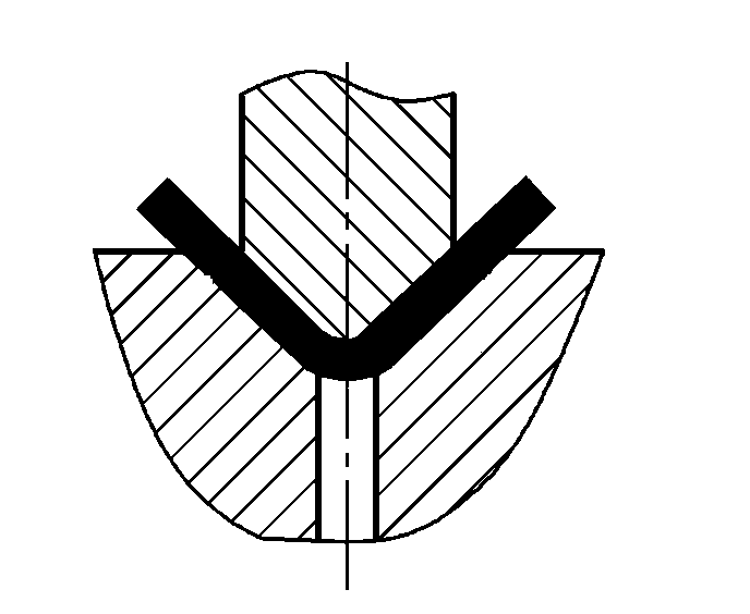 | P=(1.4Bt2σb)/(r+t) | |
 | P=(1.6Bt2σb)/(r+t) | ||
 | P=(1.4Bt2σb)/(r+t)+Aq | ||
 | P=(1.6Bt2σb)/(r+t)+Aq |
Table 5 Unit correction pressure q value (unit: MPa)
| Material | Material thickness / mm | |||
| <1 | 1~3 | 3~6 | 6~10 | |
| Aluminum | 15~20 | 20~30 | 30~40 | 40~50 |
| Brass | 20~30 | 30~40 | 40~60 | 60~80 |
| 10~20 steel | 30~40 | 40~60 | 60~80 | 80~100 |
| 25~30 steel | 40~50 | 50~70 | 70~100 | 100~120 |
The bending work of V-shaped bending parts can be calculated using the following formula.
Wv=mFvh
Where
h=0.5L~0.4(t+r)
Where
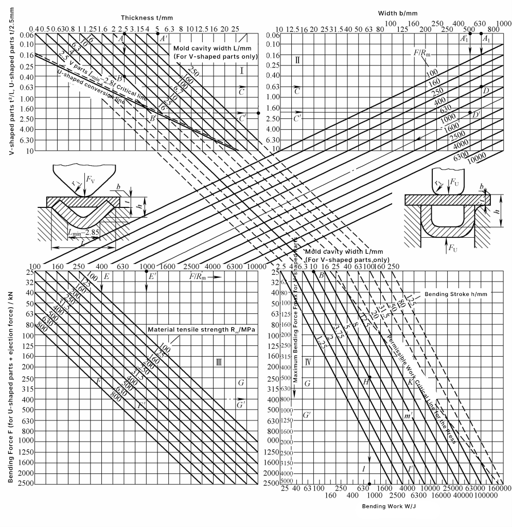
Figure 2 shows the graphical calculation column chart for the bending force and bending work of V-shaped and U-shaped bending parts. This chart is convenient to use, the graphical calculation is quick, and the results are close to reality, suitable for on-site use.
Note: The symbols in the chart mean the following:
Graphical calculation example. Given a V-shaped bending part with t=2.5mm, opening width of the bending die L=10mm. In area I of Figure 2, t2/L=0.63 (see ABC line). Given the width of the bending part b=630mm, tensile strength of the material R m =630MPa, in areas II and III, find the A1 DEF line, and in area III, along the right extension line, find the FG line, resulting in a bending force Fv =250kN.
In area IV, considering the leveling straightening pressure, the total pressure is F∑ =2F=500kN. The bending working stroke h=0.5L=5mm, correction coefficient m=0.32, thus the bending work Wv =mF∑ h=800J, as shown in the BH line and CHI line in Figure 2.