1. Through-type Ejection
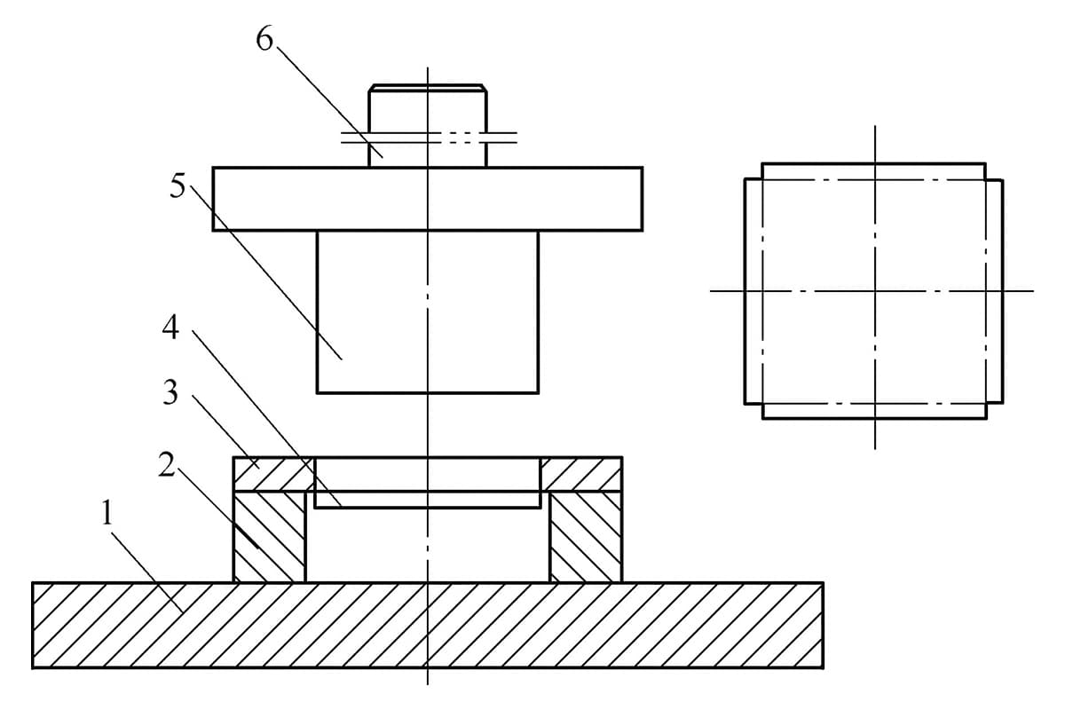
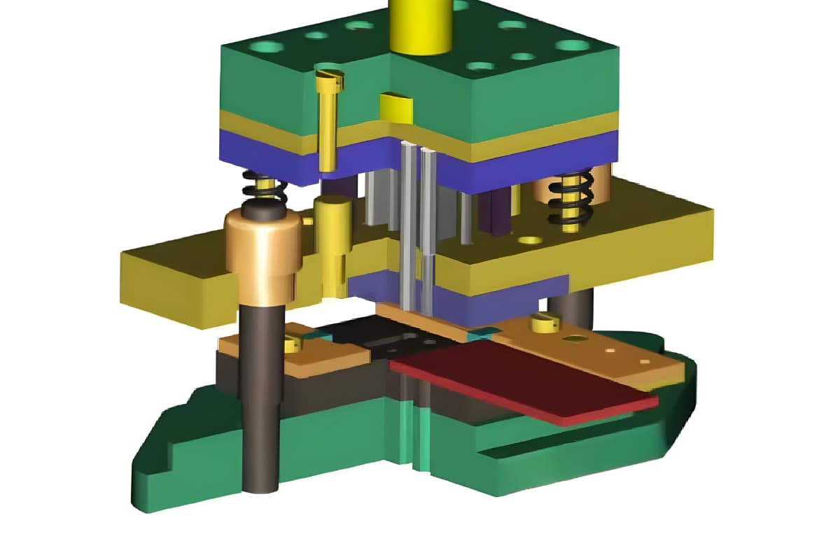
For box-shaped parts where the bending height is less than one-third of the slide stroke, a through-type ejection structure can be used as long as the flatness requirement of the bottom surface is not stringent, as illustrated in Figure 3-17.
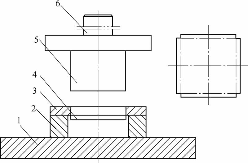
1-Lower die shoe 2-Die cushion 3-Female die 4-Workpiece 5-Male die 6-Shank
The through-type ejection bending die utilizes the material’s springback to achieve ejection. It requires the die cavity to have good rigidity. By inserting rectangular strips beneath the die cavity, the formed workpiece is ejected through the gaps between the strips. Alternatively, the lower die base can be perforated to allow direct ejection of the material.
Through-type ejection bending dies are highly efficient and facilitate automation, but are not suitable for workpieces that require a high degree of flatness on the bottom surface or where bending marks are not permissible.
2. Stripper Hook Ejection
By exploiting the difference in wall thickness before and after forming, a stripper hook can be mounted on the die cavity to disengage the workpiece from the punch. This ejection method should be used in conjunction with a stripper plate.
This method is suitable for small parts and workpieces with shallow bends.
3. Push-out Ejection
The stripper plate is shaped to match the ejection end face of the workpiece and is placed at the bottom of the die cavity. It is powered by springs, elastic rubber, or the return stroke of the press slide. This method is mainly used for bending dies of U-shaped parts.
4. Axial Ejection
This is suitable for workpieces with a straight central axis, such as closed or open loops, but not for those with a curved central axis, such as goose-neck stainless steel spouts or elbows. The mold can be manually stripped or powered by an attached inclined plate and rollers.
Under the action of the springs, the punch descends and the stripper ring retracts. As the punch returns, the rollers drive the stripper ring forward, pushing the workpiece away from the punch.
5. Knockout Rod Ejection
This method is suitable for workpieces with a large surface area and significant bending depth. The knockout rod, powered by the punch, pushes the workpiece off the punch die as the punch rises, using a knockout plate. The die structure and layout are the same as those of an inverted drop-out die.
6. Pin Ejection
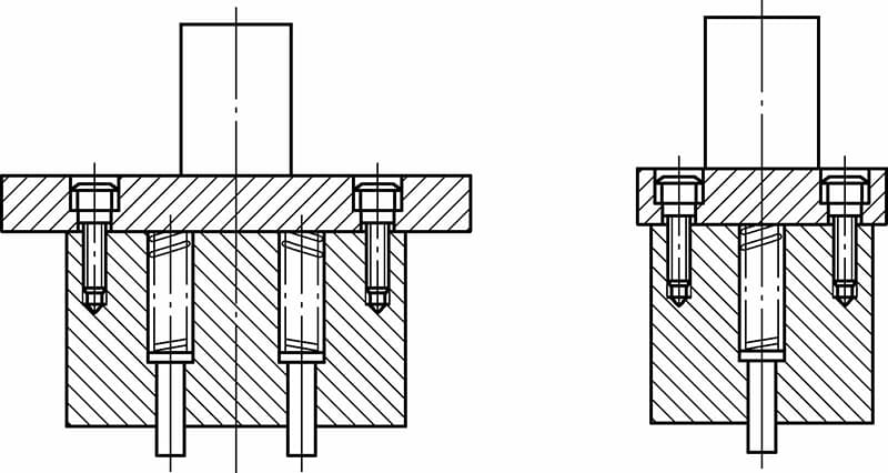
This ejection method works in conjunction with a stripper plate and is ideal for parts with a large bottom area and high flatness requirements. The pins are backed by strong springs. Once the pressure from the upper die is released, the pins reset under the spring force, pushing the workpiece off the punch die, as shown in Figure 3-18.
7. Lifting Hook Ejection
Lifting hook ejection is a forced ejection method suitable for workpieces that require relatively high ejection force after bending. Figure 3-19 illustrates a bending die for the brake cable slot of a motorcycle fork model. As the upper die moves downward, the fixed lifting hook pushes the active lifting hook to compress the leaf spring inward.
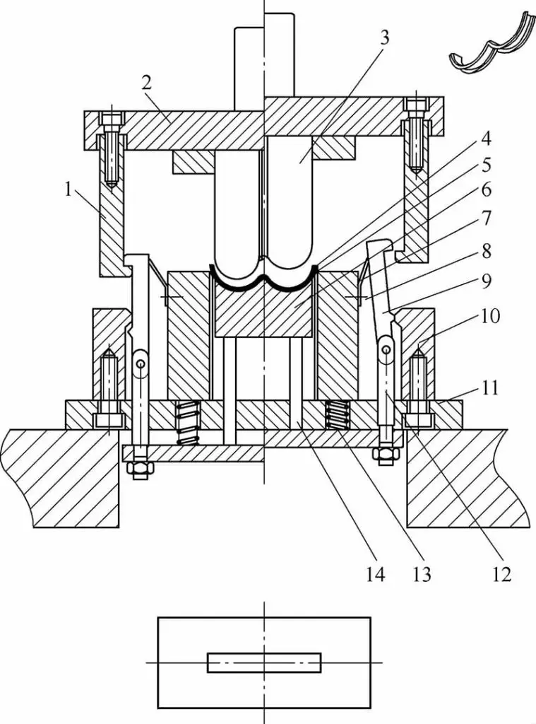
1-Fixed Lifting Hook 2-Upper Die Holder 3-Punch 4-Workpiece 5-Stripper Block 6-Die 7-Leaf Spring 8-Set Screw 9-Movable Lifting Hook 10-Punching Block 11-Lower Die Holder 12-Connecting Pin 13-Return Spring 14-Lifting Plate
At the initial stage of the upper die’s ascent, the fixed and active lifting hooks engage, lifting the workpiece out of the lower die through the lifter plate and the stripper block. Subsequently, the interaction between the knockout block and the protrusion on the active lifting hook causes them to disengage, allowing the lifter plate to reset under the spring’s force.
8. Band Ejection
When the punch die is too narrow for springs to be installed, a band ejector can be used to press the part off the punch die. After the part is separated, the ejector band retracts under the spring’s action, as depicted in Figure 3-20.
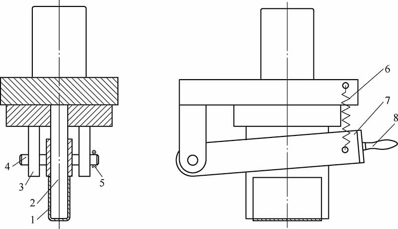
1 – Workpiece 2 – Punch 3 – Support 4 – Pin 5 – Retaining Ring Pin 6 – Spring 7 – Stripper Ring 8 – Handle

