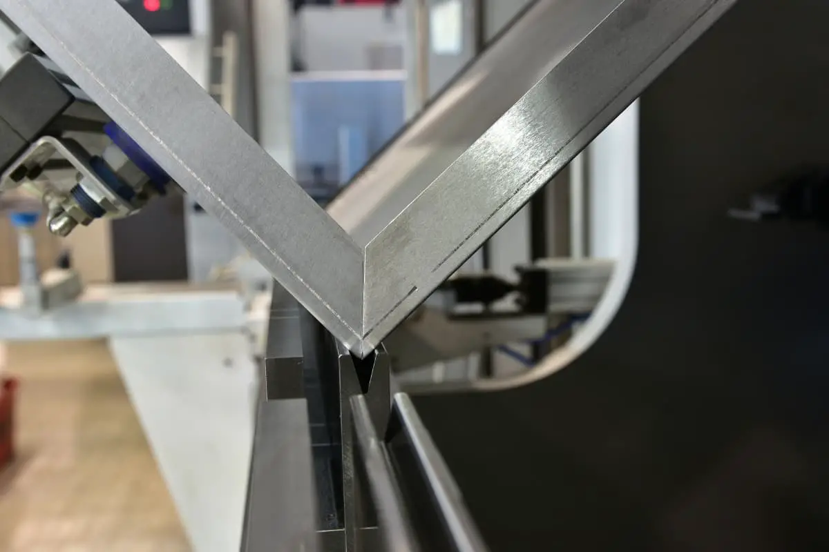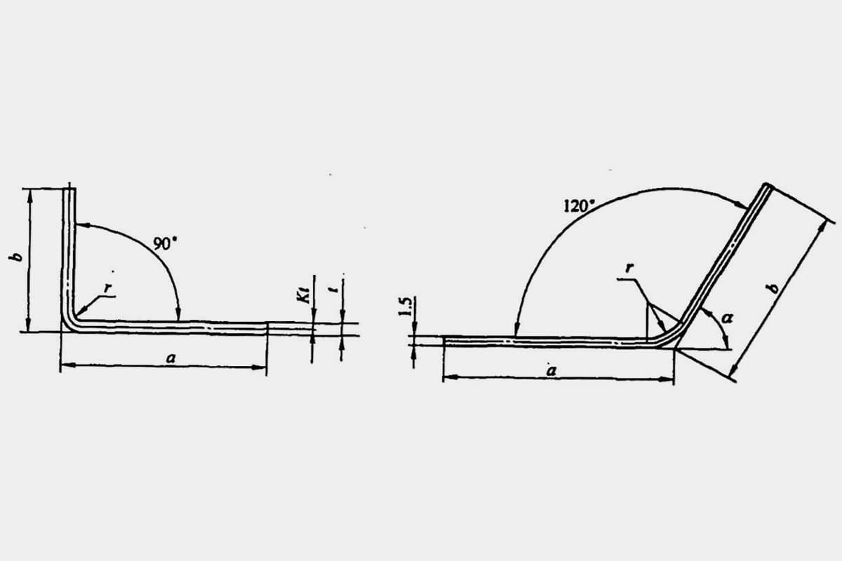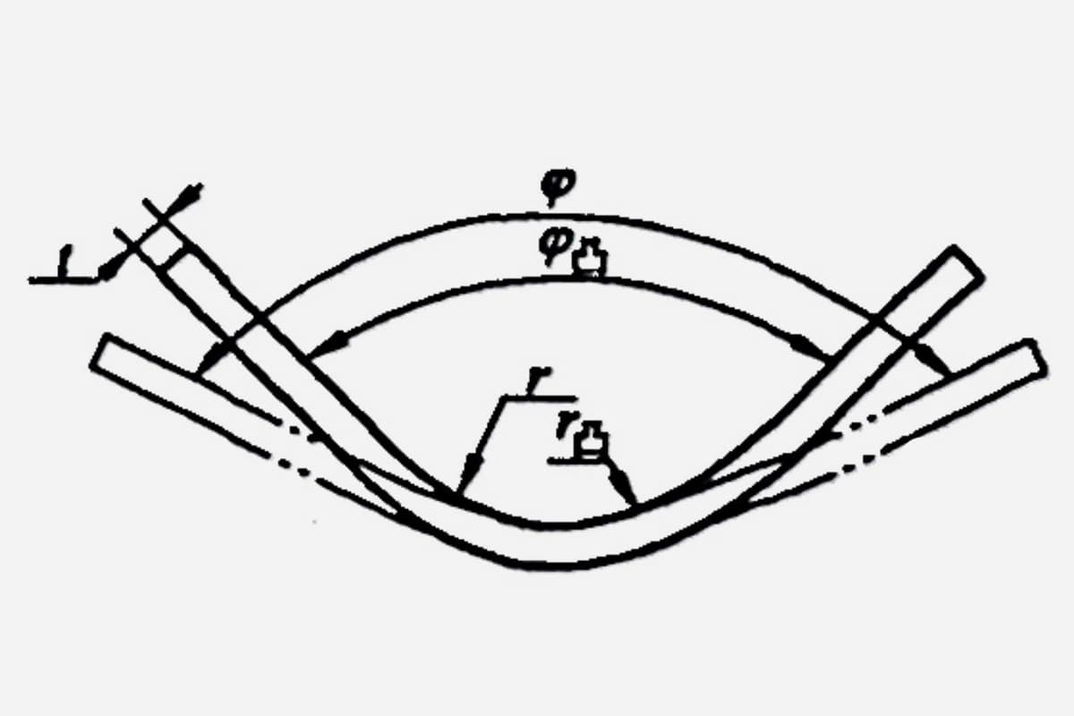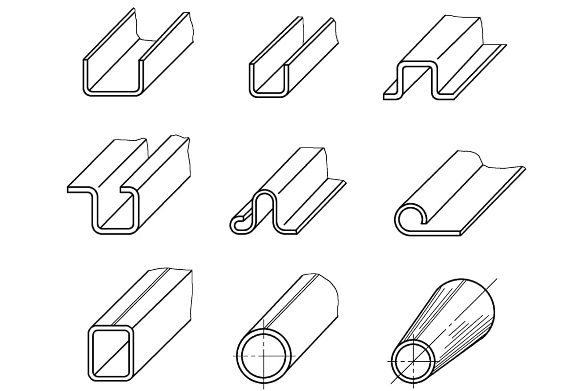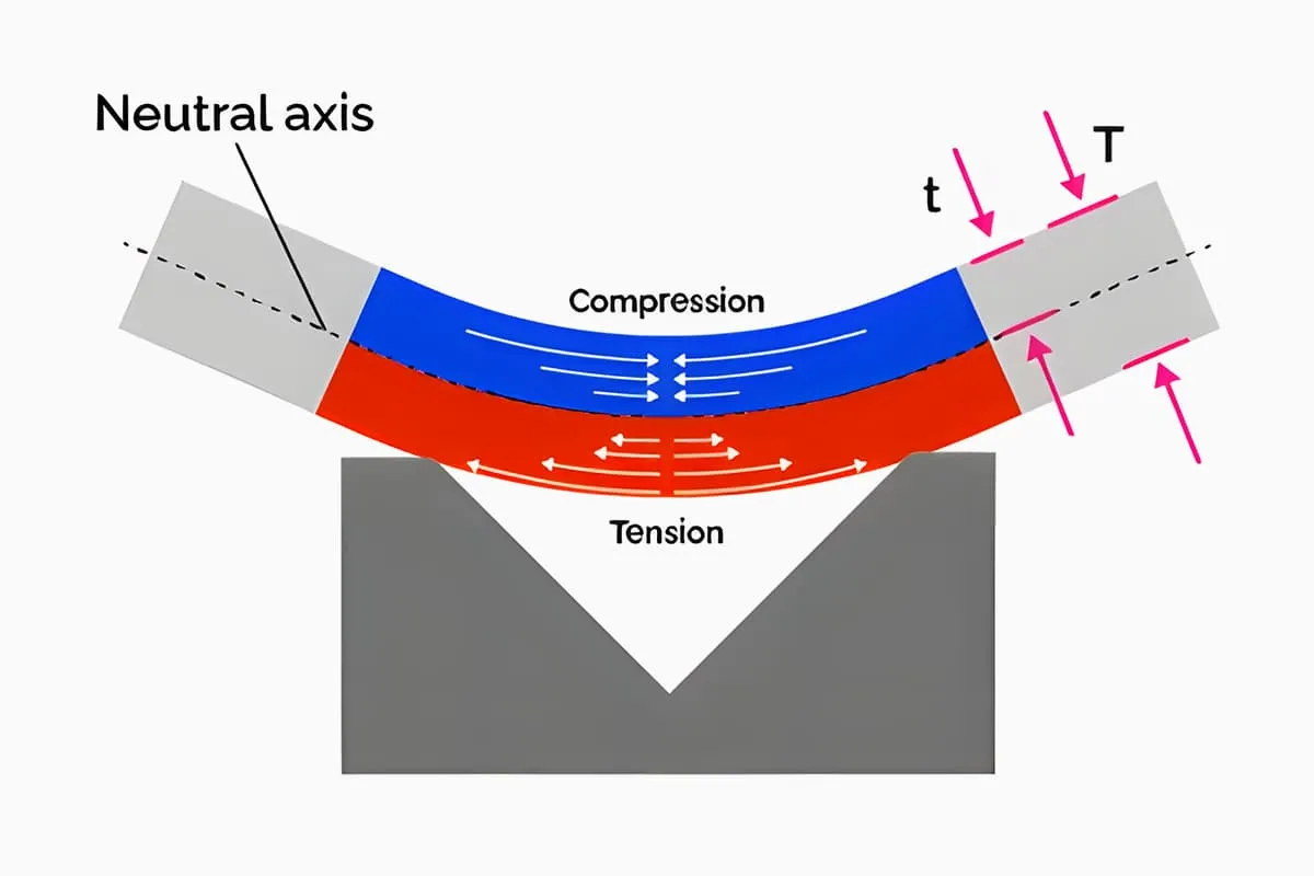
Bending is a sheet metal forming process where metal materials (sheet, profiles, pipes, etc.) are placed in a bending mold (or bending die). The materials are bent along their bending line into a certain angle and shape using a press or specialized equipment. Bending is primarily used for processing parts with large batch production, complex shapes, and high precision requirements. Figure 1 illustrates the basic principle of bending V-shaped pieces using a V-shaped bending mold.
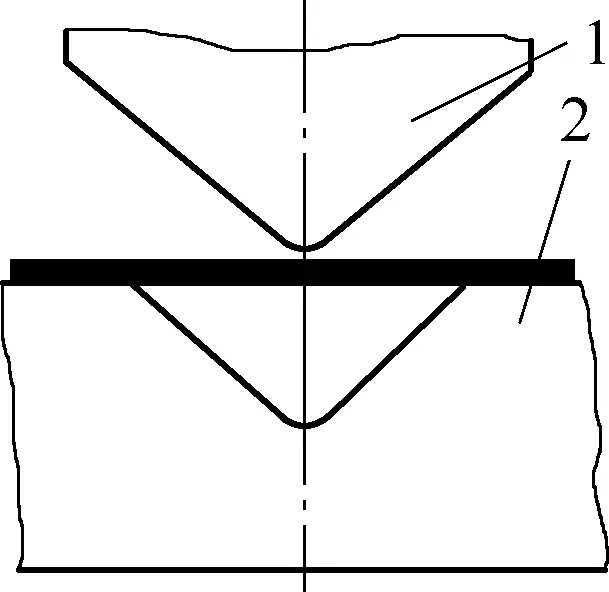
1—Punch
2—Die
The punch and die closely match the inner and outer contours of the bending workpiece. During bending, when an external force (such as the movement of a press slide) pushes the punch down, it bends the sheet placed between the punch and die into the desired workpiece.
I. Equipment and Tools for Bending
Bending causes material to undergo plastic deformation, forming it into a certain angled shape, making it one of the sheet metal forming processes. According to the basic principles of bending: the process is typically completed using a bending mold, aided by a press. In production, equipment used for bending is often similar to that used for punching, typically using a crank press, with the bending mold being the most important tool for completing the bending process.
Generally speaking, different shaped parts often require different bending molds to meet processing requirements. Additionally, the precision of the bending mold directly affects the precision of the bent parts, and it is generally advisable to keep the dimensional tolerance grade of bent parts below IT13.
1. Common Structures of Bending Molds
The shapes of bent parts are extremely varied, and thus the structures of bending molds are also diverse. The commonly used form for sheet metal bending molds is the single-operation mold, which completes one bending operation in each stroke of the press.
Bending molds can be classified according to their bending forming methods: free bending mold and corrective bending mold. Based on whether they have guiding during bending forming, they can be divided into open bending molds, mold frame guided bending molds, etc.
(1) Free Bending Mold
Figures 2a and 2b show respectively V and U shaped free bending molds, with an open type structure.
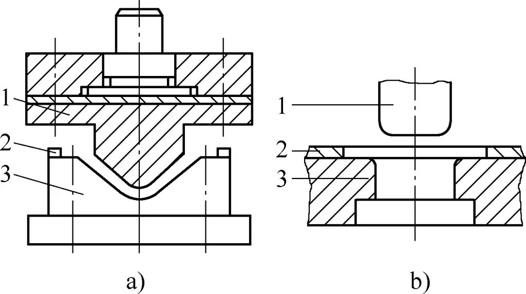
a) V-shaped open type bending mold
b) U-shaped open type bending mold
1—Punch
2—Positioning plate
3—Die
This mold is easy to manufacture and highly versatile, but when using this mold for bending, the sheet can easily slide, making it difficult to control the edge length of the bent part, resulting in low precision and uneven bottom in U shaped parts.
(2) Corrective Bending Mold
To improve the bending precision of shaped parts and prevent the material blank from sliding, a corrective bending mold as shown in Figure 3 can be used. In the bending mold shown in Figure 3a, a spring top rod 3 is used as a pressure device to prevent the blank from shifting during bending.
In the bending mold shown in Figure 3b, a pressure device is installed. During stamping, the blank is pressed between the punch 1 and the pressure plate 3, gradually going down. The material not pressed at the ends slides along the die corner and bends, entering the gap between the punch and die and forming the part into a U shape.
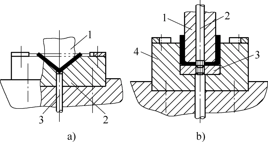
a) In the diagram:
1—Punch
2—Die
3—Top rod
b) In the diagram:
1—Punch
2—Push rod
3—Pressure plate
4—Die
Since the sheet remains under pressure between the punch 1 and pressure plate 3 during the bending process, it is possible to better control the flatness of the U shaped part bottom and ensure bending precision.
Figure 4 shows a U shaped corrective bending mold with a movable side pressure block. The movable side pressure block provides corrective action on the bent piece, with minimal spring-back. During operation, the punch descends, first contacting the blank and bending it into a U shape, then the punch shoulder presses down the movable die side pressure block.
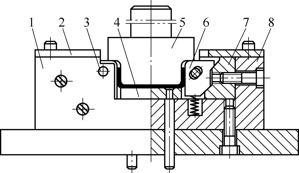
1—Baffle
2—Positioning plate
3—Pin
4—Ejector
5—Punch
6—Movable die side pressure block
7—Die slope cushion
8—Die frame
Due to the slope action, the movable die side pressure block slides towards the center, applying pressure to both sides of the bent part, thereby achieving corrective action and allowing the bent parts to meet shaping precision requirements.
2. Structure Composition of Bending Mold
As introduced above, the structure of a bending mold is similar to a punching mold and consists of punch, die, positioning device, and stripper device. The punch and die are the components that directly cause bending on the material and are the core parts of the bending mold. Typically, the punch is fixed on the upper template while the die is fixed on the lower template.
II. Determining the Bending Process Parameters
The determination of bending process parameters primarily includes the calculation of the bending blank length, calculation of bending force, and determination of the gap between bending molds.
1. Calculation of the length of the bending blank
The calculation of the length of the bending blank is the same as the calculation of the expanded length during manual bending.
2. Calculation of bending force
Bending force refers to the pressure applied by the press to complete the predetermined bending of the workpiece. Bending force is an important basis for designing bending dies and selecting press tonnage. It can be calculated using empirical formulas based on the type of bending.
(1) Bending force during free bending Ffree
According to the different shapes of the bent workpieces, the bending force Ffree during free bending can be calculated by the following formula:
1) V-shaped part Ffree=0.6Kbt2σb/(r+t)
2) U-shaped part Ffree=0.7Kbt2σb/(r+t)
In the formula
- Ffree – Bending force at the end of the stamping stroke (N);
- K- Safety factor, generally K=1.3;
- b- Width of the bent piece (mm);
- t- Thickness of the bending material (mm);
- r- Inner bending radius of the bent piece (mm);
- σb– Strength limit of the material (MPa).
(2) Bending force during corrective bending Fcorrect
Since the corrective bending force is much greater than the pressing force and the two forces act sequentially, only the corrective bending force needs to be calculated. The correction force for V-shaped and U-shaped parts is calculated by the following formula:
Fcorrect = Ap
In the formula
- Fcorrect – Corrective bending force during corrective bending (N);
- A – Vertical projection area of the corrective part (mm2);
- p – Corrective force per unit area (MPa), selected according to Table 1.
Table 1 Corrective force per unit area p (Unit: MPa)
| Material | Material thickness t/mm | |
| ≤3 | >3~10 | |
| Aluminum | 30~40 | 50~60 |
| Brass | 60~80 | 80~100 |
| 10~20 steel | 80~100 | 100~120 |
| 25~35 steel | 100~120 | 120~150 |
| Titanium alloy TA2 | 160~180 | 180~210 |
| Titanium alloy TA3 | 160~200 | 200~260 |
(3) Ejection force and discharge force FQ
Regardless of the type of bending, ejection force and discharge force are required during press bending. The ejection force and discharge force FQ can be approximately taken as 30% to 80% of the free bending force, i.e.,
FQ=(0.3~0.8)Ffree
(4) Press tonnage Fpress
During free bending, considering the impact of the ejection force and discharge force during the press bending process, the press tonnage is
Fpress ≥ Ffree + FQ = (1.3 ~ 1.8) Ffree
During corrective bending, the corrective force is much greater than the ejection force and discharge force, so the component of FQ becomes insignificant. Therefore, the press tonnage is
Fpress ≥ Fcorrect
3. Determination of the bending die gap
The size of the gap between the punch and the die, like the fillet radius, greatly affects the required bending force and the quality of the parts.
When bending V-shaped parts, the gap between the punch and the die is controlled by adjusting the closed height of the press. There is no need to determine the gap in the die structure.
When bending U-shaped parts (commonly referred to as double-angle bending in production), a proper gap must be selected. The size of the gap is significantly related to the quality of the workpiece and the bending force. If the gap is too large, the springback will be significant, reducing the accuracy of the part. If the gap is too small, the required bending force will increase, and the pressed part will become thinner. If the gap is too small, it may cause scratches or fractures, reducing the life of the die, and even causing damage to the die.
For general bending parts, the gap can be found in Table 2, or it can be directly calculated using the following approximate formula:
- Non-ferrous metals (pure copper, brass) z = (1 ~ 1.1) t
- Steel z=(1.05~1.15)t
When higher workpiece accuracy is required, the gap value should be appropriately reduced, taking z = t. In production, when there is no high requirement for material thickness reduction, to reduce springback and other issues, a negative gap can also be used, i.e., z = (0.85 ~ 0.95) t.
Table 2 Gap between bending die punch and die (Unit: mm)
| Material thickness t | Material | |
| Aluminum alloy | Steel | |
| Gap z | ||
| 0.5 | 0.52 | 0.55 |
| 0.8 | 0.84 | 0.86 |
| 1 | 1.05 | 1.07 |
| 1.2 | 1.26 | 1.27 |
| 1.5 | 1.57 | 1.58 |
| 2 | 2.1 | 2.08 |
| 2.5 | 2.62 | 2.58 |
| 3 | 3.15 | 3.07 |
| 4 | 4.2 | 4.1 |
| 5 | 5.25 | 5.75 |
| 6 | 6.3 | 6.7 |
4. Calculation of the dimensions of the working part of the bending die
The design of the working part of the bending die mainly involves determining the fillet radius of the punch and die, the dimensions of the punch and die, and the manufacturing tolerances.
Generally, the fillet radius of the punch is taken as slightly smaller than the inner fillet radius of the bent part. The fillet radius of the inlet of the die should not be too small; otherwise, it will scratch the material surface. The depth of the die must be appropriate. If it is too small, the free parts at both ends of the workpiece will be large, causing significant springback, unevenness, and affecting the part quality. If it is too large, it will consume more die steel and require a longer press stroke.
(1) V-shaped part bending die structure
The structure of the V-shaped bending die is shown in Figure 5. The determination of the thickness H and groove depth h of the die is shown in Table 3.
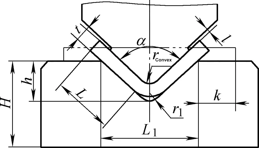
Table 3 Determination of the die dimensions H and h for bending V-shaped parts (Unit: mm)
| Material thickness | <1 | 1~2 | 2~3 | 3~4 | 4~5 | 5~6 | 6~7 | 7~8 |
| h | 3.5 | 7 | 11 | 14.5 | 18 | 21.5 | 25 | 28.5 |
| H | 20 | 30 | 40 | 45 | 55 | 65 | 70 | 80 |
Note:
1. When the bending angle is 85°~95° and L1=8t, rConvex=r1=t.
2. When k (small end) ≥2t, the h value is calculated by the formula h=L1/2-0.4t.
(2) Determination of the fillet radius rConcave and depth L0 for V-shaped and U-shaped bending
For determining the fillet radius rconcave and depth L0 of V-shaped and U-shaped bends, refer to Figure 6 and Table 4.
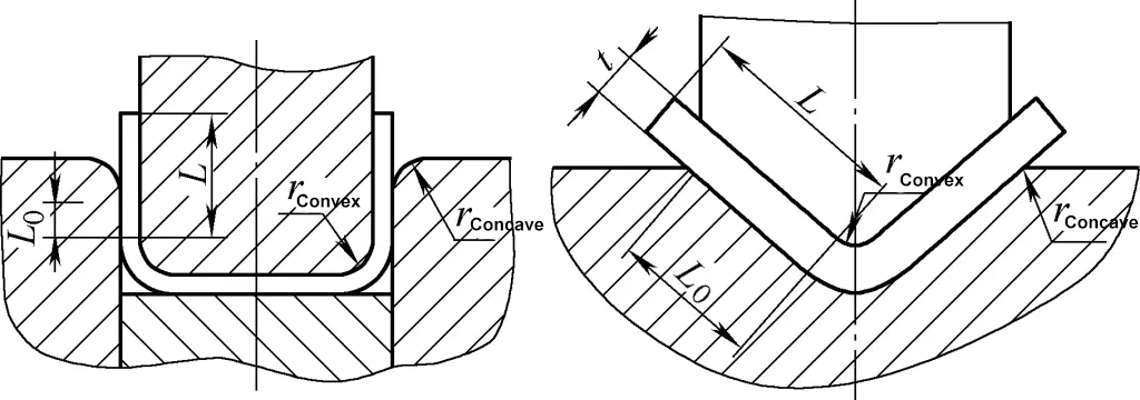
Table 4 Fillet radius rconcave and depth L0 of bending mold (unit: mm)
| Bending edge length L | Material thickness t | |||||||
| ~0.5 | 0.5~2 | 2~4 | 4~7 | |||||
| L0 | rconcave | L0 | rconcave | L0 | rconcave | L0 | rconcave | |
| 10 | 6 | 3 | 10 | 3 | 10 | 4 | — | — |
| 20 | 8 | 3 | 12 | 4 | 15 | 5 | 20 | 8 |
| 35 | 12 | 4 | 15 | 5 | 20 | 6 | 25 | 8 |
| 50 | 15 | 5 | 20 | 6 | 25 | 8 | 30 | 10 |
| 75 | 20 | 6 | 25 | 8 | 30 | 10 | 35 | 12 |
| 100 | 25 | 6 | 30 | 10 | 35 | 12 | 40 | 15 |
| 150 | 30 | 6 | 35 | 12 | 40 | 15 | 50 | 20 |
| 200 | 40 | 6 | 45 | 15 | 55 | 20 | 65 | 25 |
(3) Calculation of the width dimensions of bending punch and die
General principle: When the outer dimensions of the workpiece need to be ensured, the die is used as the reference (i.e., the die is made to nominal size) and the clearance is taken on the punch. If the inner dimensions of the workpiece are marked, the punch is used as the reference (i.e., the punch is made to nominal size) and the clearance is taken on the die.
When the outer dimensions of the workpiece need to be ensured, the width dimensions of the die Lconcave and the punch Lconvex are calculated according to the following formulas respectively:
Lconcave=(Lmax-0.75Δ)+δ concave0
Lconvex = (Lconcave – 2z)0 – δconvex
When the inner dimensions of the workpiece need to be ensured, the width dimensions of the punch Lconvex and the die Lconcave are calculated according to the following formulas respectively:
Lconvex=(Lmin+0.75Δ)0-δ convex
Lconcave = (Lconvex + 2z) + δconcave 0
In the formulas
- Lmax – maximum width dimension of the bend (mm);
- Lmin – minimum width dimension of the bend (mm);
- Lconvex – punch width (mm);
- Lconcave – die width (mm);
- z – unilateral clearance between punch and die (mm);
- Δ – tolerance of bend width dimension (mm);
- δconvex and δconcave – manufacturing deviations for punch and die respectively (mm), generally selected according to IT9 level.
III. Installation and adjustment of the bending mold
Using the bending mold on the press to perform bending processing is the main form of bending processing. During processing, the stamping operation procedures should be strictly followed to prevent maloperations. To ensure proper bending of parts, the bending mold installation and adjustment must first be done correctly.
1. Method of installing the bending mold
Bending molds are divided into those with and without guidance. Their installation methods are fundamentally the same as those for blanking dies. Like blanking dies, apart from adjusting the clearance between the punch and die and the ejection system, the upper positioning of the bending mold on the press must also be adjusted. Typically, the following method is used:
First, the upper bending mold is roughly adjusted on the press slider. Then, a spacer slightly thicker than the blank (generally 1 to 1.2 times the blank thickness) or a test piece is placed between the lower die ejection plate and the lower surface of the upper punch. Afterward, using the method of adjusting the connecting rod length, manually turn the flywheel (for presses with a rigid clutch) or jog the motor (for presses with a friction clutch) until the slider can pass through the bottom dead center without obstruction. Once this is achieved, the lower die can be fixed for trial stamping.
Before the trial stamping, the spacer placed in the mold should be removed. After passing the trial stamping, all fastening parts should be tightened again before formal production.
2. Key points for adjusting the bending mold
When processing with a bending mold, to ensure the quality of the bent parts, the bending mold must be meticulously adjusted, paying attention to the following aspects.
(1) Adjustment of the clearance between punch and die
Generally, after adjusting the upper mold position on the press according to the installation method mentioned above, the clearance between the upper and lower molds is simultaneously ensured.
For guided bending molds, since the relative positions of the upper and lower molds on the press are determined entirely by the guiding components, the lateral clearance between the upper and lower molds is also ensured simultaneously. For unguided bending molds, the lateral clearance between the upper and lower molds can be adjusted using paper spacers or standard samples. Only after the clearance is adjusted can the lower template be fixed for trial stamping.
(2) Adjustment of the positioning device
The positioning shapes of the bending mold’s positioning parts should match the blank. In the adjustment, the reliability and stability of the positioning must be ensured. If inaccurate positioning is found after trial stamping using locating blocks and pins, the positioning should be timely adjusted or the positioning parts replaced.
(3) Adjustment of the ejection and stripping device
The ejection system of the bending mold should be ample; the springs or rubbers used for ejection should have enough elasticity. The ejector and stripping systems should operate flexibly and smoothly, with no jamming or seizing. The ejection force acting on the bent parts should be adjusted evenly to ensure that the parts’ surfaces are flat and free from deformation or warping after ejection.
(4) Precautions for adjusting the bending mold
While adjusting the bending mold, if the upper mold position is too low, or if spacers or other debris are left in the mold, the upper and lower molds may collide violently at the bottom dead center during stamping, potentially damaging the mold or the press.
Therefore, if there are ready-made bent parts on the production site, they can be placed directly in the working position of the mold for mold installation and adjustment, thus preventing accidents.
IV. Operation of typical sheet metal bending parts
In the bending forming of sheet metal components, considering the reduction of production costs and the influence of processing equipment and manufacturing capabilities, the press method using a die combined with a press is commonly adopted, forming various typical sheet metal bending operation techniques. The main aspects are as follows.
1. Suppression of Large Circular-to-Square Ducts
Large and thick circular-to-square ducts are often made using radial templates for hand bending, but for larger and thicker materials, these ducts are usually pressed using radial templates with a press machine.
Figure 7 shows the pressing method for circular-to-square ducts (1/4 expanded material) (the making of the radial template is the same as for hand bending).
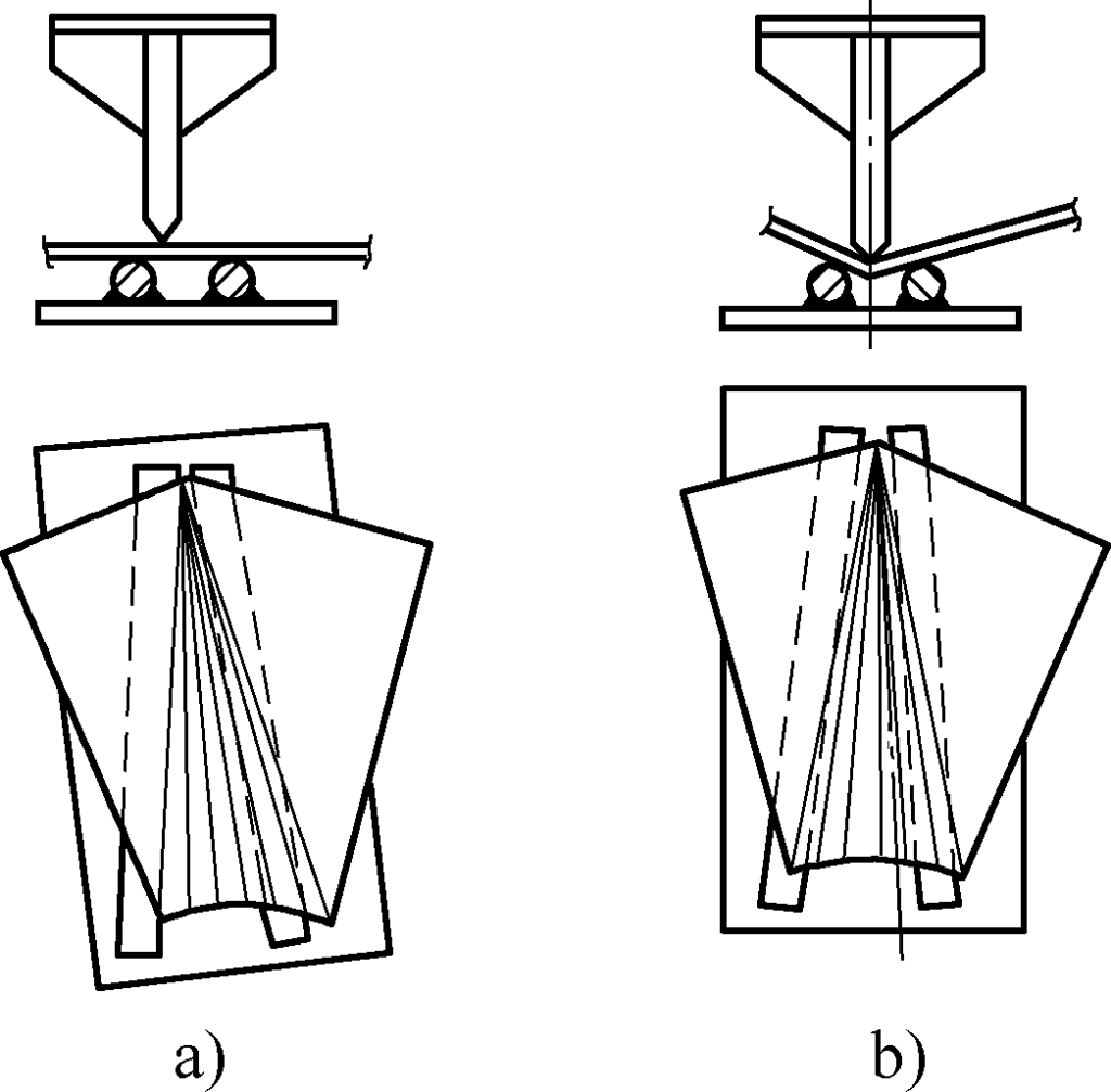
First, divide the circular upper end (circular part) of the workpiece into several equal parts, and draw several radial lines from the corresponding square part (square part) of the lower end. Press along the lines. Figure 7a shows the position relationship between the punch and die round steel when the first stroke is pressed. Place the square end of the material in the middle of the small end of the template, and the first transition line of the circular end, which is the edge where the arc and the plane intersect, should be placed on the edge of the round steel. The first stroke should fall on this line, and then press the second stroke without moving the template.
Figure 7b shows the pressing method for each stroke along the near-end line. At this time, the position of the die can be adjusted at any time to ensure the punch mainly falls in the middle of the die. Start with the two ends and then the middle part, and after pressing each small section, check a template to gauge the extent of pressing.
When checking with the template, the template should not be vertical to the plate but inclined at an angle towards the small end of the material. Pressing should follow the principle of under rather than over-correcting because it’s much easier to correct for under-bending than over-bending. If it is under-bent, you can appropriately press a few more transition lines until it fits the template.
Of course, the above operation also applies to the pressing of small circular-to-square ducts.
2. Pressing of a Right Circular Frustum
The production of a right circular frustum can use hand bending or roll bending with a plate rolling machine. However, for the right circular frustum shown in Figure 8, the small port diameter is too small, making it inconvenient and unsuitable for manual processing or rolling with a plate rolling machine. It can only be formed by pressing with a template. The design of the template is key for pressing.
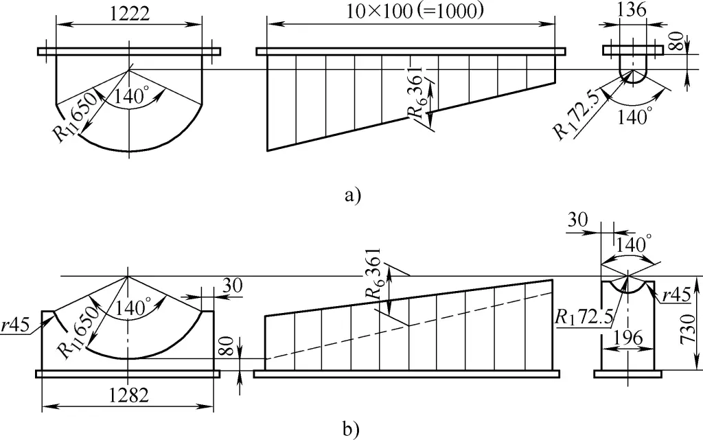
The template is generally made according to the 1/n section of the sector material, pressing out the corresponding 1/n material in one go; it can also be made with any small angle, pressing the material section by section. Both methods can achieve the purpose of forming.
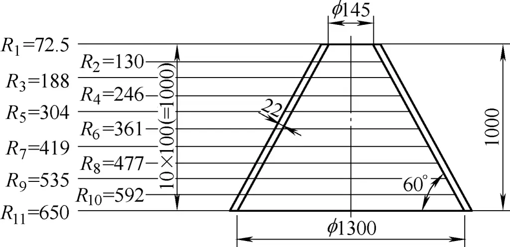
Figure 9 shows the template made based on 1/3 blanking and more than 1/3 of the material. Figure 9a shows the punch, and Figure 9b shows the die. The die corner radius r is designed as twice the plate thickness, with r being 45mm.
(1) Calculation of Each Vertical Plate Rn
Each vertical plate Rn is calculated using the following formula (see Figures 8 and 9):
Rn = -R11 – nh/tanα
In the formula
- R11– Inner radius of the large end of the frustum;
- h- Divided height of the frustum, with each division being 100mm in this case;
- α- Bottom angle of the frustum given by design.
For example R6 =[650 – (5×100) / tan60°] mm = 361mm.
(2) Calculation of the Width of Punch and Die
The width of the punch and die is calculated using the following formulas (see Figures 10 and 11):
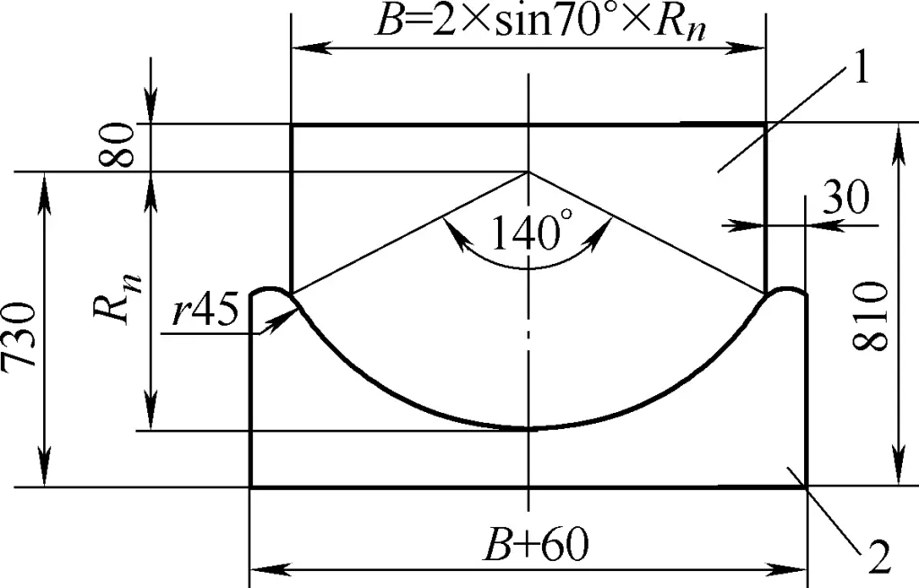
1—The nth Punch
2—The nth Die

1) Punch Width B=2Rnsin70°.
Eg: B6=(2×361×sin70°)mm=678mm.
2) Die Width B6′= (678+60)mm=738mm.
3) Lowest Height of Die h6= (730-361)mm=369mm.
The dimension 730 is the distance from the axis of the frustum to the upper plane of the base plate.
(3) Production Method of Punch and Die
To more accurately explain the production of punch and die, take as an example the production method of the sixth punch and die shown in Figure 11.
Under the premise of ensuring 730mm below and 80mm above the axis of the frustum, draw an arc with O6 as the center and R6=361mm as the radius. The intersection with the width calculated for the punch and die forms the contours of the sixth punch and die.
Based on practical experience, for both hot and cold pressing, due to the small rise height of the 1/3 segment under the strong pressure of the machine, shrinkage and rebound are not considered, nor is plate thickness. Using the inner skin radius of the frustum (radius marking the inner shape of the frustum), draw an arc and cut in one go. This gives the actual arc of the punch and die for the corresponding position, ensuring the designed curvature after pressing.
3. Pressing of a Small Frustum
The forming of small frustums, due to their small volume, generally involves thin plates, although there are also thick plate small frustums. Forming methods can use a large hammer and an arc groove hammer on a radial template, but for efficiency and labor-saving, a small press machine can also be used. For convenience, materials are mostly divided into two halves, rarely as whole materials (when height is lower, whole materials are also possible).
(1) Pressing of Half-Sector Material
For the small frustum shown in Figure 12, if expanded material is made into a half-sector shape, a horizontal pressing template like Figure 13 can be used. Without fixing the die, pre-bend, press arcs, and check with templates until the shape is achieved. The pressing method is basically the same as hand bending. If the frustum material is higher, you can extend the upper length, as shown in the double-dotted line part 4 in Figure 13.


1—Die
2—Punch
3—Mold Handle
4—Arbitrarily Extendable Part
(2) Pressing of Whole-Sector Material
When expanded material is used as a whole material, the template design is as shown in Figure 14. The internal cavity space should be larger than the maximum dimensions of the frustum (maximum dimensions refer to frustum height and large end diameter). The frame-type punch is designed to accommodate the formed frustum. The pressing method is basically the same as hand bending.

1—Radial Template
2—Frame-Type Punch
3—Mold Handle
4. Pressing of angle steel rings
There are many forming methods for angle steel rings. They can be bent on a section bending machine, rolled on a plate rolling machine, bent manually, or pressed on a press using a mold. The specific method to be used depends mainly on the equipment of the unit and the requirements for the angle steel rings.
Figure 15 shows a construction drawing of an outer bent angle steel ring. This angle steel ring is made of equal-angle steel with a specification of 63×63×6 and has an inner diameter of ϕ4800mm after forming. It is pressed on a press using a mold.

(1) Design of the mold
Figure 16 shows the mold designed for pressing the outer bent angle steel. This mold can also press a single piece, but the distortion is larger after pressing because the edges in contact with the punch are compressed and the vertical surface embedded in the groove is stretched, forming a bend.
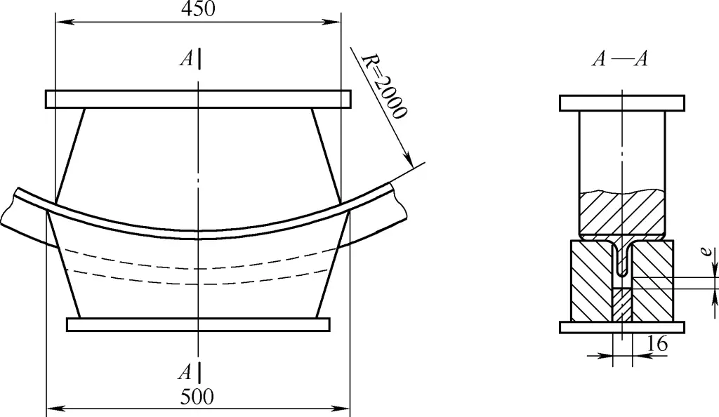
Another type of deformation also occurs simultaneously, that is, the plane pressed by the punch and die becomes thinner and elongated after squeezing, and the root shrinks and extends, causing a vertical bend in the direction of the edge. The overlap of these two deformations results in distortion.
To prevent or reduce the distortion of angle steel, a method of pressing after welding two angle steels in relative positioning can be adopted. This is because the two planes pressed by the punch and die will produce opposite vertical bends after the welding, canceling out each other’s forces and preventing distortion.
(2) Die clearance and radius treatment
To accommodate double angle steel pressing, the die mold should be designed in the form of angle steel, with the groove clearance approximately 4-5mm thicker than the total thickness of two plates. Here it is designed with a clearance of 16mm to facilitate the movement of the double angle steel.
The forming by pressing adopts the suspension method (providing sufficient redundancy in the direction of pressing forming to facilitate the adjustment of pressure and deformation). The radius of the punch and die can be smaller, based on the pressure to achieve the design curvature. In this example, the radius of the punch and die pressing area is R=(2400-400)mm=2000mm, ensuring sufficient height for the vertical edge of the angle steel.
(3) Operating method
During pressing, insert from one end, not too deep according to the principle of “better less than more”. Depending on the curvature, it can be pressed in one pass or multiple passes, aiming for minimal or no wrinkles on the vertical surface until achieving the slightly over-curved state. If there are any local discrepancies, thin plates can be padded at appropriate positions of the punch and die for adjustment.
After pressing, the curvature should slightly exceed the required curvature of the sheet metal part, mainly because:
① It is easier to handle an over-curve than an under-curve;
② After cutting the weld point of the angle steel, part of the curvature will be released;
③ Various degrees of distortion will occur after cutting the weld point of the angle steel, and part of the curvature will be released during the correction of the distortion.
V. Common Defects in Bent Parts and Solutions
Common defects in bent parts mainly include cracks, uneven bottom, etc. The causes may be related to the bending material itself, the tuning of the bending mold, or operator error. Solutions must be taken based on careful analysis of the causes of the defects. For common defects in bent parts and solutions, see Table 5.
Table 5 Common Defects in Bent Parts and Solutions
Quality Condition | Sketch | Cause | Solution |
Crack | 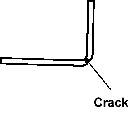 | 1) The bending radius of the punch is too small 2) The burr edge is on the outside of the bend, and the plate material has low plasticity Bending outside, low plate plasticity 3) The hardening layer of the blank during stamping is too large Excessive blank hardening layer during stamping | 1) Appropriately increase the radius of the punch fillet 2) Place the burr edge on the inside of the bend 3) Use annealed or more plastic material, perpendicular or at a 45° angle to the bending line |
Uneven bottom | 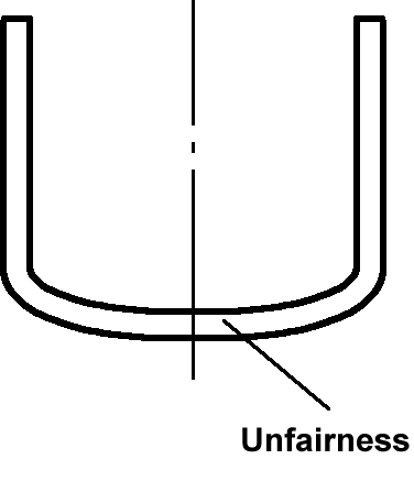 | During bending, the plate and the bottom of the punch are not tightly attached | Use a mold with an elastic pressing plate to apply sufficient pressure to the blank at the beginning of bending, and finally correct the bent part |
Warping | 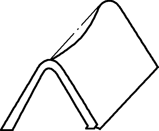 | Caused by the strain state in the deformation zone, with compressive strain on the outside and tensile strain on the inside relative to the neutral layer along the bending line direction, resulting in warping | 1) Use corrective bending to increase unit area pressure 2) Adjust the punch and die based on the amount of warping |
Off-center hole | 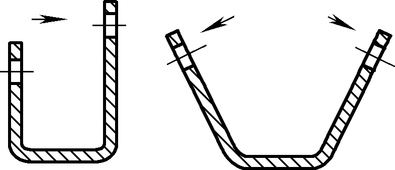 | 1) The blank shifted during bending, offsetting the hole centerline Shifting during bending, offsetting the hole centerline 2) Spring-back after bending caused hole centerline tilt Hole centerline tilt due to spring-back | 1) Accurately locate the blank to ensure consistent bending height on both sides 2) Use positioning pins or pressing plates to prevent the blank from shifting 3) Reduce workpiece spring-back |
Unstable straight arm height | 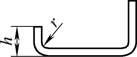 | 1) The height h is too small 2) Asymmetric die fillet 3) Blank displacement during bending process | 1) The height h dimension should not be less than the minimum bending height 2) Correct the concave die fillet 3) Use elastic pressure device or process hole positioning |
Surface scratches | 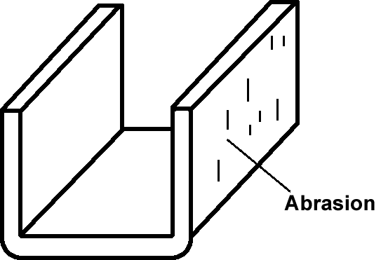 | 1) Metal particles adhere to the surface of the mold on the working part 2) The fillet radius of the concave die is too small 3) The clearance between the convex and concave dies is too small | 1) Remove dirt from the surface of the working part of the mold, reduce the surface roughness value of the convex and concave dies 2) Properly increase the concave die fillet radius 3) Use a reasonable clearance between convex and concave dies |
Bending line is not parallel to the center line of the two holes | 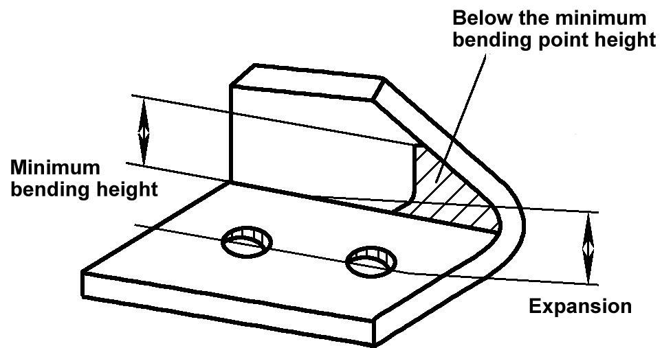 | The straight edge height of the bent part is less than the minimum bending height, and an opening appears in the part below the minimum bending height | In the design of the workpiece, ensure that the straight edge height of the bent part is greater than or equal to the minimum bending height. When the straight edge height is less than the minimum bending height, leave enough straight edge height first and remove the excess after bending. |
Displacement | 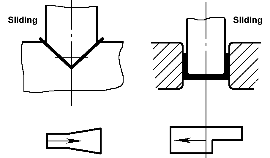 | When bending asymmetrical workpieces, the frictional forces on both sides are different as the blank slides into the concave die, leading to dimension displacement | 1) Use a mold with an elastic pressure plate 2) Ensure the blank is accurately positioned in the mold, and if possible, perform paired bending before cutting |
Hole deformation | 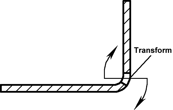 | The hole edge is too close to the bending line, leading to compression deformation inside the neutral layer and tension deformation outside, causing the hole to deform | Ensure the distance from the hole edge to the center of the bending radius r is greater than a certain value, or set process holes at the bending position to reduce the impact of bending deformation |
Bending angle change | 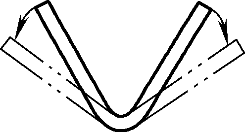 | During plastic bending, elastic deformation occurs. When the bent workpiece is removed from the mold, elastic recovery occurs, causing the bending angle to change | 1) Correct the angles of the convex and concave dies with a predetermined springback angle to achieve compensation 2) Use correction bending instead of free bending |
Bulging at the bending end | 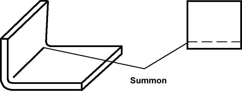 | Due to longitudinal compression and shortening of the inner metal layer of the neutral layer during bending, and elongation in the width direction, bulging occurs at the edge in the width direction, especially noticeable for thick plates bent at a small angle | Pre-make arc cuts at both ends of the bending part, place the blank flash on the inner side of the bend |
Twist | 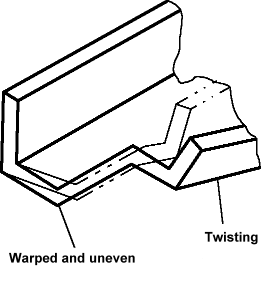 | Due to significant differences in width and bend edge height on both sides of the blank, unequal bending deformation resistance occurs. The narrower side with lower bend edge height is prone to twisting. Additionally, large notches on both ends and the inability of the ejector to press the material exacerbate the twist at the bottom with notches | Add process allowances on both sides, cut off the allowances after bending. Install guide plates on the twisting side and notch locations to mitigate twisting |
Poor cross-sectional shape, unclear edges | 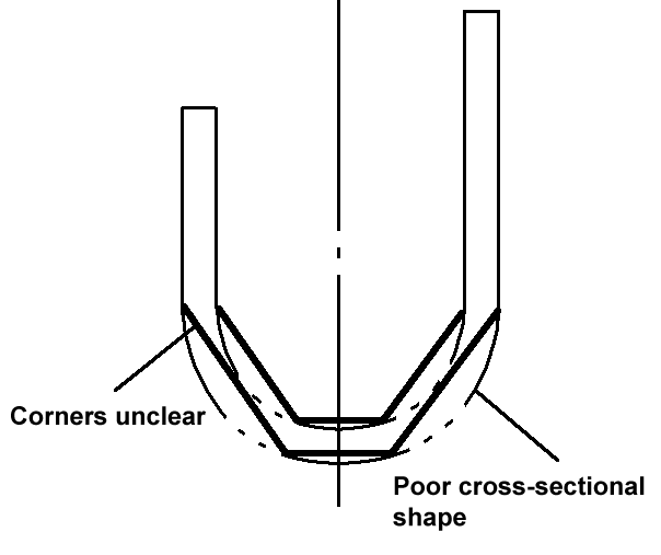 | Due to the conical shape of the bottom of the bending punch, there is free space between it and the concave die and top plate. The blank cannot fit tightly to the punch’s conical surface, resulting in an unsatisfactory cross-sectional shape and a large fillet transition at the workpiece’s bottom and wall junction | Add a rubber pad on the top plate to gradually wrap the blank tightly around the punch during bending, ensuring the workpiece shape is entirely determined by the punch, thus producing qualified workpieces |
Sidewall instability | 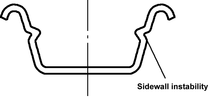 | 1) The first bending only bends 1/4 arc of the semi-finished product. Due to poor metal flow during roll hem, high pressure results in sidewall instability 2) The roughness of the R surface of the roll hem concave die is high, increasing friction resistance during roll hem | 1) Bend the semi-finished product into a 1/2 arc 2) Reduce surface roughness at the fillet of the roll hem concave die 3) Replace elastic components to increase pressure on the bottom of the workpiece |

