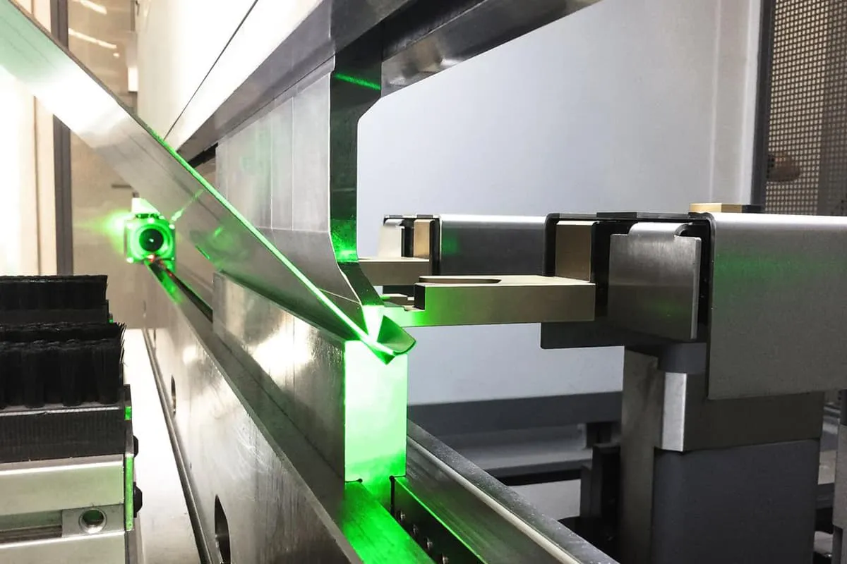
Adjustments to the press brake machine:
- Adjustment of the ram upper limit:
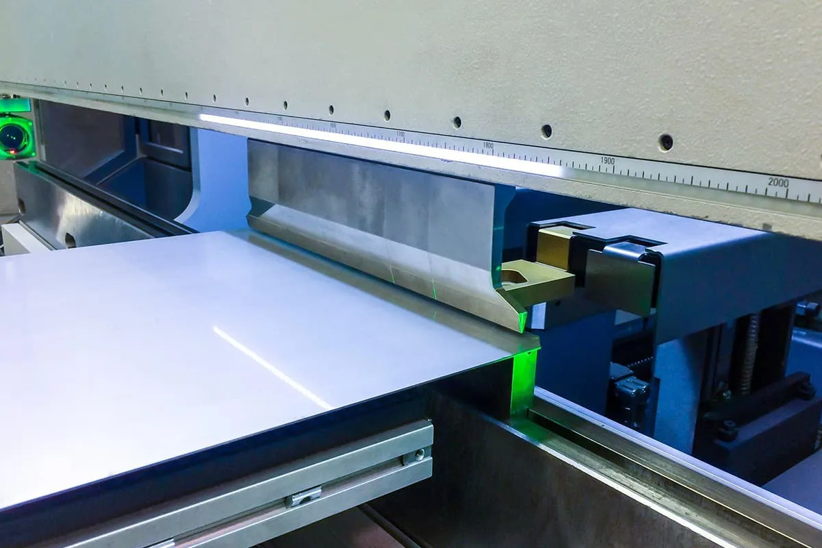
By adjusting the position of collision block II, the rising ram can be stopped at the desired top dead center position. This optimization reduces the ram stroke distance, minimizes cycle time, and enhances overall productivity.
- Adjustment of the ram’s slow motion:
During the ram’s descent, collision block “I” activates the stroke switch, initiating slow motion. The duration of this slow motion can be fine-tuned using a variable resistor, allowing for precise control over the bending process.
- Adjustment of the upper and lower die clearance:
a. With the ram at top dead center, use the control buttons on the lower right of the operating table to set the initial clearance. This clearance should exceed the plate thickness and be further adjusted based on the required bending angle. Fine adjustments can be made using the handwheel, with each increment of 0.1mm displayed on the digital readout.
b. For inconsistent angles at the workpiece ends, disengage the left and right rotating connections by loosening the support pins and moving the connecting rod. Use the handwheel to adjust one end of the mechanical limit, allowing for precise angle correction at the workpiece ends.
Note: After adjustment, ensure sleeve 18 is returned to its original position and the support pin is securely tightened to prevent mechanical failures.
c. If the angles at the ends are consistent but the middle angle deviates, fine-tune the upper die. Bring the upper die close to the lower die slot, slightly loosen the adjustment block and upper die contact plate screws, then gently tap the adjustment block in the middle section. In areas where the middle angle is insufficient, allow the upper die to protrude slightly. Tighten the support pin and perform test bends until the entire workpiece angle meets the specified tolerance.
- Adjustment of the bending force:
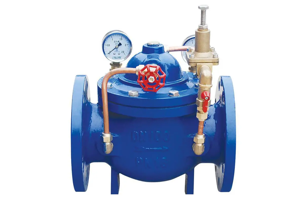
Calculate the required bending force in kilonewtons using the provided table or bending force formula for the specific sheet metal. Convert this to the indicated pressure value P using Table 1. Adjust the relief valve handwheel to produce a force slightly exceeding the calculated bending force, ensuring optimal performance.
- Adjustment of the back gauge distance:
The back gauge, crucial for longitudinal positioning during bending, is adjusted via motor control using the front button box. The digital readout displays adjustments in 0.1mm increments, with a handwheel available for more precise positioning.
- Foot pedal operation:
The foot pedal switch offers ergonomic control over the ram’s vertical movement, enhancing operator efficiency and comfort during the bending process.
Testing and Operation of the Press Brake Machine
Prior to testing, apply calcium-based lubricating grease to all designated lubrication points as per the lubrication label. Fill the hydraulic system oil tank with 46# hydraulic oil. Replace the oil after the first month of operation, then annually based on usage conditions. Ensure the minimum oil temperature remains above 15°C (59°F).
Initial testing procedure:
- Start the oil pump motor unit and allow it to idle.
- Test machine functions using “jog” mode.
- Verify performance of “single” and “continuous” actions.
- Check stroke and back gauge control accuracy.
Only proceed to operational setup once the machine demonstrates normal functionality:
- Calculate or reference the required bending force and V-die opening size based on plate thickness and bending length. (V-die opening should typically be ≥8 times the plate thickness)
- Align upper punch and lower die centers precisely.
- Set and adjust the clearance between upper punch and lower die.
- Position the back gauge accurately.
- Select appropriate action mode (“jog”, “single”, or “continuous”) using the mode selector switch.
- Place the workpiece centrally on the machine’s work table and conduct a test bend.
- Fine-tune die clearance if necessary, adjusting the upper die adjustment blocks as needed.
Operational considerations:
- Monitor all seals for leakage, replacing promptly if detected.
- Ensure bending occurs at the machine’s centerline to maintain workpiece accuracy and machine integrity. Avoid uneven or off-center loading.
- For unavoidable one-sided operations, limit the load to <100 kN. Whenever possible, use two-sided bending to distribute the load evenly.
- When bending plates <600 mm in length, do not exceed 100 kN per 100 mm of length. Never operate at full capacity (1000 kN) for these shorter pieces.
- Verify correct motor rotation direction (counterclockwise) during testing.
Machine Maintenance, Care, and Troubleshooting
Anyone who operates or maintains this machine must carefully read this manual, understand the main structure, performance, and use of the machine, and carry out regular maintenance and care work. Record daily usage to facilitate future reference.
- A dedicated person must be responsible for operating the machine, and the operator should be familiar with and correctly follow the operating procedures and calculate the bending force of the workpiece.
- Keep the oil clean and unobstructed to prevent the oil pump from sucking air, causing pipeline vibration or rupture, and avoid the locking and rubbing of related hydraulic components.
- The machine adopts decentralized lubrication. Lubrication should be added according to the indication diagram of the machine’s lubrication points, based on working conditions (the left wall panel of the machine is equipped with a lubrication label).
- The bending force of the workpiece should not be greater than the nominal force.
- Do not perform one-sided or single-point load work.
- Electrical and hydraulic components must ensure flexible action and correct position.
- Adjust the clearance between the upper and lower dies based on the thickness of the bending material, which is generally about 1mm larger than the thickness of the plate. The specific value may be adjusted according to the plate thickness, but it must be greater than the plate thickness to avoid damaging the dies due to the clearance.
- Users must regularly have the random spare parts provided with the machine.
- If abnormal phenomena or noises are found, stop immediately and find the cause for inspection and repair.
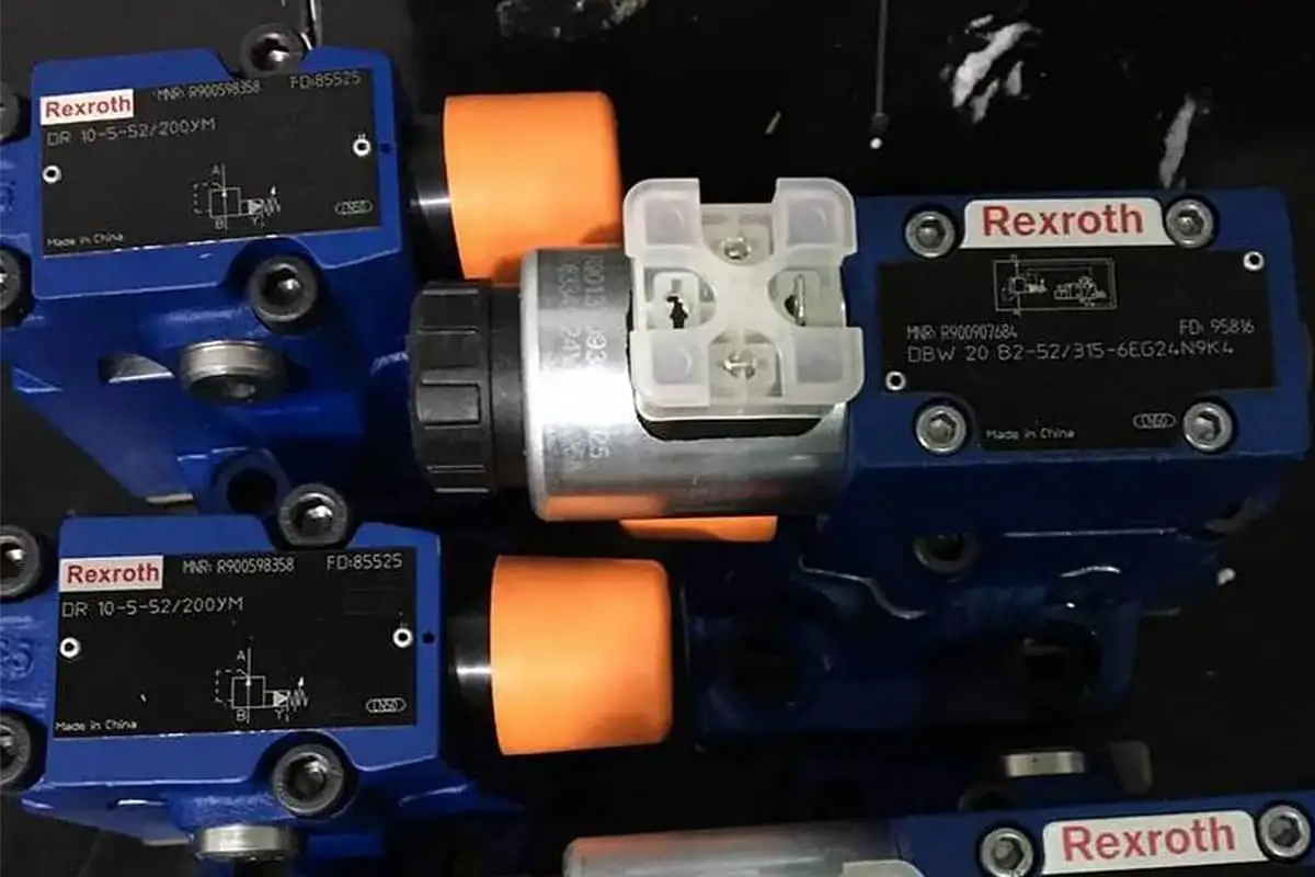
Common hydraulic system failures of the press brake include valve malfunction or slow switching, leaks, and faults in the solenoid valve.
(1) Valve malfunction or slow switching often results from inadequate lubrication, compromised spring mechanisms, or contamination of the valve’s sliding components with oil residue or debris.
To address this issue, begin by inspecting the oil mist separator’s functionality and verifying the lubricating oil’s viscosity. If necessary, replace the lubricating oil, thoroughly clean the valve’s sliding components, or install new springs and valves. Regular predictive maintenance using vibration analysis or oil analysis can help prevent such issues.
(2) Extended operational periods can lead to wear or damage of critical valve components, including the valve core sealing ring, valve stem, and valve seat. This deterioration may result in internal leakage, sluggish valve response, or improper switching.
In such cases, replace the affected components (sealing ring, valve stem, and valve seat) or, if extensive damage is present, opt for a complete valve replacement. Implementing a condition-based maintenance program can help identify these issues before they lead to system failure.
(3) Solenoid valve malfunctions can occur due to several factors: clogged intake and exhaust ports (from oil sludge or debris accumulation), inadequate sealing, a stuck moving iron core, or electrical circuit faults.
For mechanical issues, thoroughly clean the solenoid valve components, paying particular attention to the moving iron core and surrounding areas. For potential circuit failures, which typically manifest as control circuit or solenoid coil issues, follow a systematic troubleshooting approach:
First, manually actuate the switching valve’s knob several times under rated pressure to verify proper operation. If the valve switches correctly, focus on circuit diagnostics. Use a multimeter to measure the solenoid coil voltage, ensuring it meets the rated specification. If voltage is insufficient, investigate the power supply and relevant stroke switch circuits within the control system.
If the switching valve fails to operate correctly under rated voltage, examine the solenoid coil connection for loose fittings or poor contact. Disconnect the plug and measure the coil’s resistance. Resistance values outside the manufacturer’s specified range indicate a damaged coil requiring replacement.
To enhance system reliability, consider implementing advanced diagnostic tools such as thermal imaging for early detection of electrical issues or ultrasonic testing for identifying internal leaks. Additionally, integrating a computerized maintenance management system (CMMS) can help track component life cycles and schedule preventive maintenance tasks effectively.

