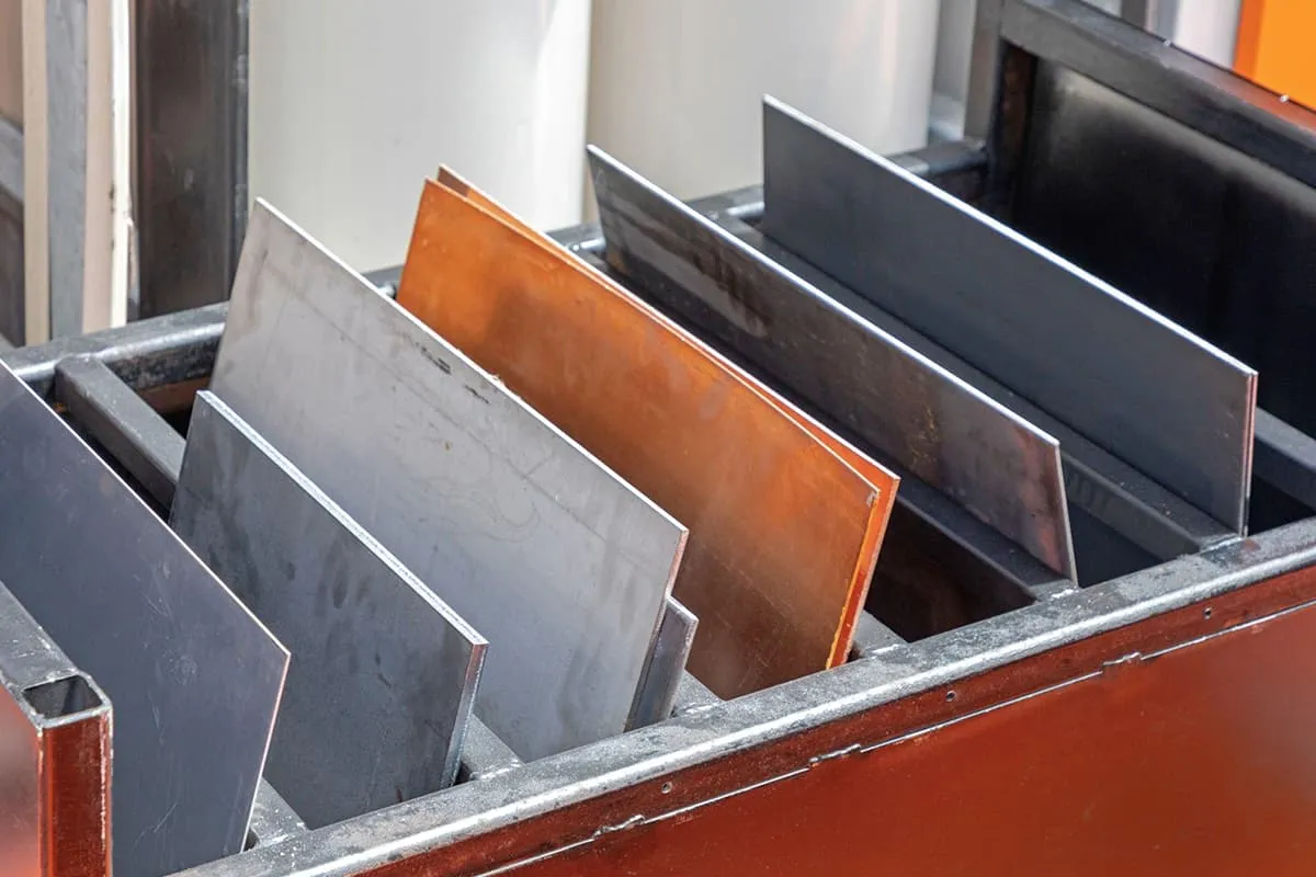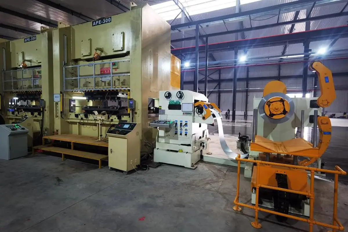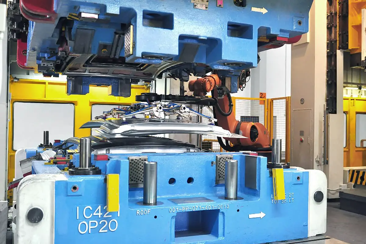
Sheet metal bending is another form of sheet metal forming, mainly through the sheet metal bending machine to perform linear bending of the sheet metal, suitable for processing narrow and long linear parts. The bending operation of the bending machine relies on the upper and lower bending dies fixed on the ram and the table to complete.
I. Bending equipment and tools
According to different bending methods, the sheet metal bending machine has two forms: bending and press bending, commonly referred to as bending machines and press braking machines, respectively. Currently, the most widely used bending machine is the hydraulic sheet metal bending machine.
As shown in Figure 1, the structure of the W67Y—160 type sheet metal bending machine is as follows: W indicates bending machine, 67 indicates sheet metal bending press, Y represents the code for hydraulic transmission, and 160 signifies the nominal pressure of the press is 160kN. The sheet metal bending machine consists of a frame, ram, worktable, and hydraulic cylinder. During operation, high-pressure oil is used as power, utilizing the hydraulic cylinder and piston to move the ram and die, thus completing the press bending of the sheet metal.
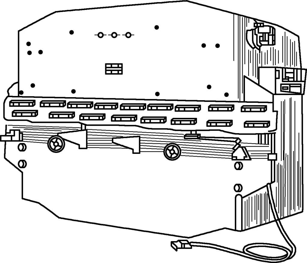
With the development of computer control technology, traditional sheet metal bending machines have been gradually upgraded to CNC. The stroke adjustment of the ram and the rear stopper positioning adjustment mostly adopt electric quick adjustment and manual fine adjustment, and are often equipped with digital display devices, and optional CNC systems to achieve automatic control of the rear stopper and ram stroke.
The positioning accuracy of this CNC mechanism can generally reach ±0.1mm or higher, enabling continuous rapid bending of workpieces with multiple different bending angles, significantly improving production efficiency.
Regardless of the type of equipment used for sheet metal bending, the processing is primarily achieved through bending dies installed on the bending machine. The bending dies installed on the bending machine can be divided into two categories: general and special dies. Figure 2 shows the end face shapes of general bending dies.
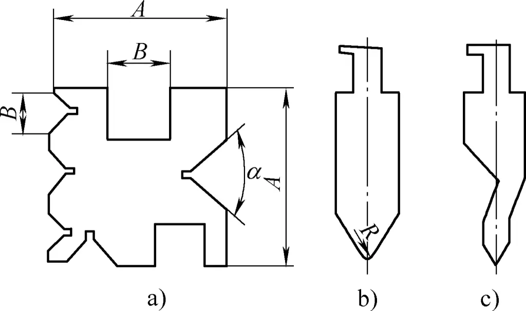
a) General concave die
b) Straight arm punch
c) Curved arm punch
The upper die is generally V-shaped, with two types: straight arm and curved arm. The upper die with a smaller fillet angle is made at 15°, and the fillet radius of the upper die consists of several fixed dimensions to form a set, which can be replaced according to the needs of the workpiece.
The lower die generally has several fixed grooves on the four sides to adapt to the bending of parts by the machine tool, usually V-shaped, but some are rectangular, which can bend obtuse and acute angle parts. The length of the lower die is usually equal to or slightly longer than the working table. The height of the upper and lower dies needs to be determined based on the closing height of the machine tool. When using bending dies, the bending angle of the bent parts is usually less than 18°.
For bending parts with large production volume or special shapes, special bending dies must be used. Special bending dies can be used in combination with general bending dies or for individual part bending. Figure 3 shows special bending dies used on bending machines.
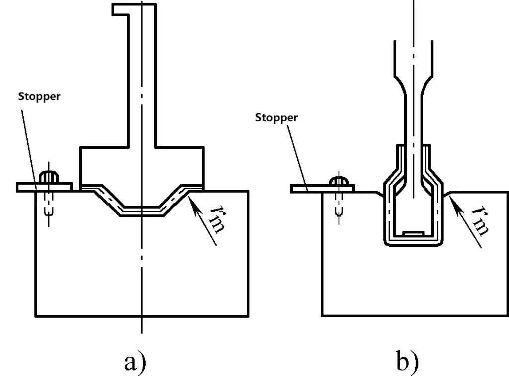
Using the special die shown in Figure 3a can achieve one-time forming of multiple bending points, which is highly efficient. The die shown in Figure 3b is a special bending die used for the last process. Because the part has a small opening, the general bending die can only complete the bending of the previous processes.
II. Bending operation techniques
Regardless of which type of bending machine or bending die is used, the following operating methods should be followed during bending processing.
1. Operating steps and methods of the bending machine
Before operating the bending machine, preparations must be made, including the following: removing obstacles from the worktable and around the machine tool, and lubricating the machine tool; checking if all parts of the machine tool are functioning properly, and repairing any issues promptly, especially ensuring that the foot pedal is flexible. If there is a continuous running phenomenon, do not use it.
Generally speaking, the bending machine can be operated according to the following methods and steps:
1) Lower the bending machine ram to the lowest position, adjust the lowest point of the ram so that the closing height to the worktable is 20-50mm greater than the total height of the upper and lower bending dies.
2) Raise the ram and install the upper and lower dies. The general procedure is to place the lower die on the worktable first, then lower the ram and install the upper die. When installing the upper die, keep both ends parallel, and push the upper die to the middle position of the ram from one end of the ram’s die slot while moving, ensuring balanced force on the machine tool, and securely fix with screws.
To prevent the upper die from falling and injuring the lower die or hands during installation, place several wooden blocks on the lower die, preferably several wooden rods of the same diameter. This not only prevents the above accidents but also, when the upper die is supported by the wooden rods, it is parallel when pushing the upper die, saving effort and ensuring safety.
3) Activate the ram adjustment mechanism, allowing the upper die to enter the lower die slot, and move the lower die to align the centerline of the upper die with the centerline of the lower die slot, then fix the lower die.
Currently, on some bending machines, for convenient installation and adjustment of the upper and lower dies, the lower die is also designed as a lower die pad and lower die assembly, connected by a U-shaped notch. Although this form is convenient for subsequent die replacement, the initial installation and adjustment should still follow the above steps.
4) Raise the ram, adjust the stopper mechanism at the back of the worktable according to the bending size, making the upper die opening coincide with the bending line of the sheet metal. If the equipment has a digital display or CNC function, electric adjustment can be adopted, with positioning size directly displayed or controlled by programming. If the equipment does not have electric adjustment function, manual adjustment can be used for positioning size during blank operation.
The structure of the backgauge mechanism of the bending machine is shown in Figure 4, where the bracket 5 is fixed in the T-slot on the side of the workbench by the fastening handle 6 and can be adjusted up and down. The ram 2 can move back and forth along the bracket 5 to adapt to the required position. If the adjustment amount is small, the backgauge plate 1 can also be adjusted back and forth by the fine-tuning nut 4 and fixed with the fastening handle 3.
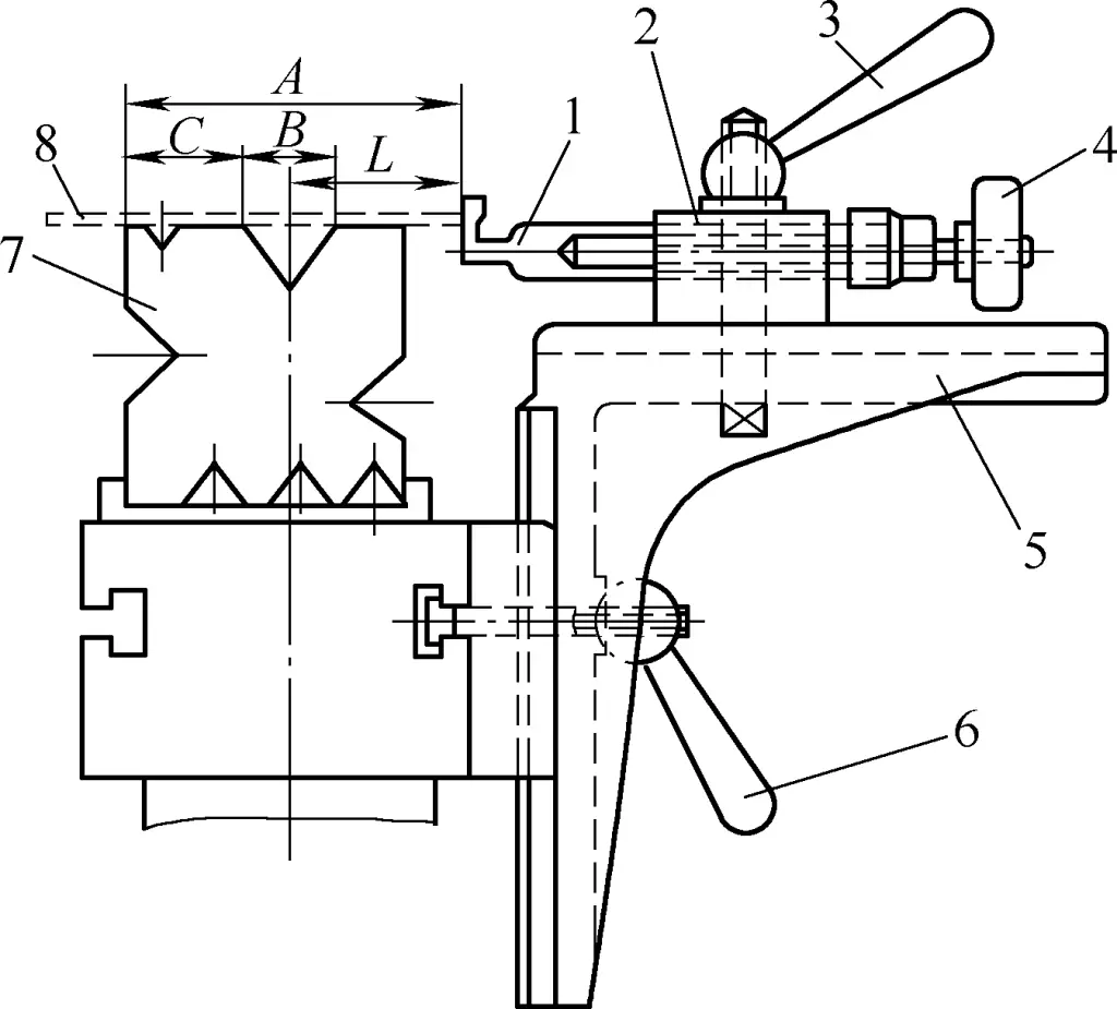
1—Backgauge Stopper
2—Ram
3, 6—Fastening Handle
4—Fine-tuning Nut
5—Bracket
7—Lower Die
8—Blank
During operation, generally mark the measurement A value [A=L+B/2+C, where A is the distance (mm) from the side of the lower die to the backgauge plate; B is the width of the lower die groove (mm); C is the distance (mm) from the side of the lower die to the edge of the lower die groove; L is the distance (mm) from the bending line to the edge of the blank]. The A value needs to be properly adjusted after a trial bend, and the bending size can only be determined after being qualified in the first inspection, self-inspection, and special inspection.
5) Adjust the bending angle as required. To meet the requirements, it is easy to adjust the bending angle by adjusting the depth of the upper die into the lower die. Generally, trial bending a few times with waste material can determine this.
2. Bending Sequence
For parts that require multiple bends to form, the bending sequence is generally carried out from the outside to the inside, that is, first bending the angles at the ends, then bending the middle parts. Moreover, the previous bend must consider providing reliable positioning for the subsequent bend, and the subsequent bend should not affect the previously formed part, as shown in Figure 5.

3. Common Bending Methods
Using a general bending machine with some special dies for bending is not only fast in production but also very economical. Therefore, it is widely used in production.
Figure 6 shows the bent parts and their bending dies for common edge bending.
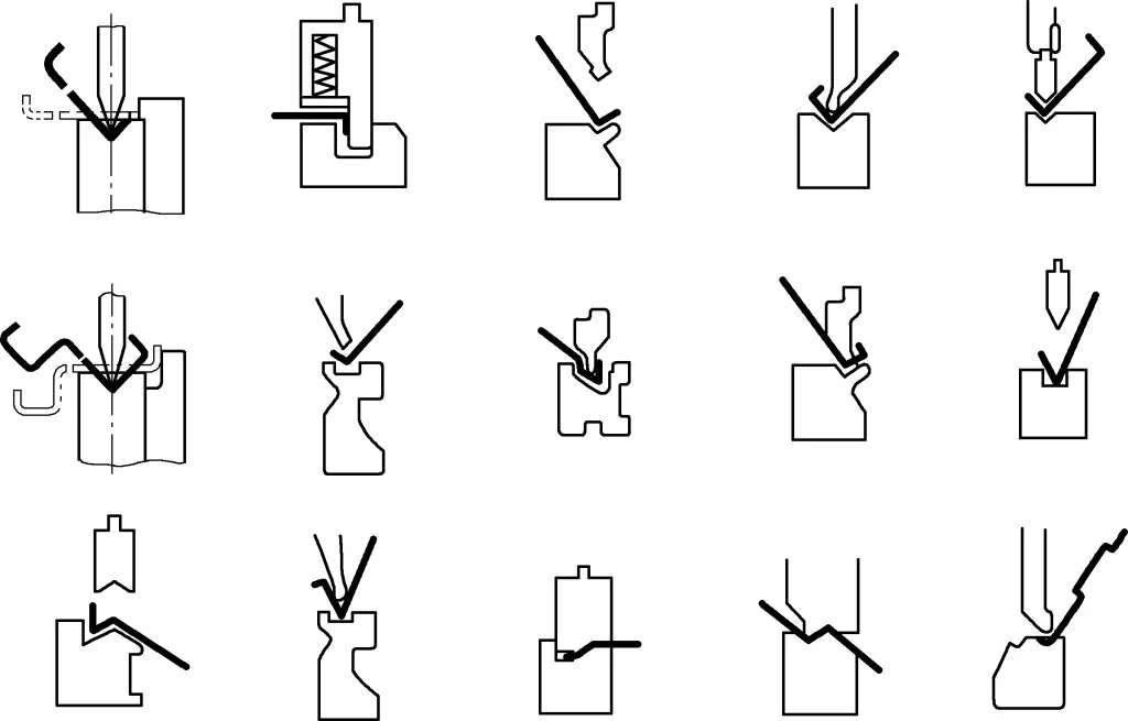
4. Precautions During Bending Operations
Pay attention to the following matters during bending operations:
1) When bending blanks that already have edge bends, the distance from the center of the lower die groove to its edge should not be greater than the straight edge length of the bent part, as shown in Figure 7a, the dimension d must be smaller than the dimension c; otherwise, the blank cannot be placed. When bending semi-finished products that have been bent into a hook shape, a lower die with a relief groove should be used, as shown in Figure 7b.
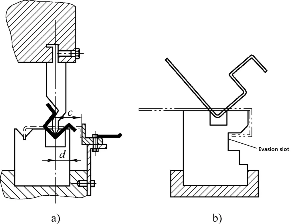
2) The selection of the upper die also needs to be based on the shape and size requirements of the part. The radius of the rounded end of the upper die should be slightly smaller than the bending radius of the part. Generally, a straight-arm type is used, but when interference occurs with the straight-arm type, a curved-arm type upper die should be used.
3) When bending complex parts with multiple angles using universal molds, adjustments to the backgauge plate and changes of the upper and lower dies are required based on the number of bends, bending radius, and the shape of the parts.
The bending sequence is very important, as it not only affects the structure of the mold and the quantity of bent parts but also sometimes determines whether the part can be made. The general principle is to bend from the outside to the inside in sequence, that is, first bend the outer angles and then the inner angles. The previous bend must consider providing reliable positioning for the subsequent bend, and the subsequent bend should not affect the shape of the previous bend.
4) When using a universal bending die to bend parts on a bending machine, the width of the lower die groove B (see Figure 2) should be greater than twice the sum of the inner bending radius R and the material thickness t, plus a 2mm clearance, i.e., B>2(t+R)+2, so that the blank will not be obstructed or produce indentations and scratches during bending.
Meanwhile, to reduce bending force, a wider groove should be selected for hard materials, whereas a narrower groove should be chosen for softer materials, as a large groove can bend the straight edge into an arc shape.


