How to Calculate Sheet Metal Weight: Essential Formulas
Ever wondered how to quickly calculate the weight of sheet metal? This article unveils a simple formula that takes the…
Have you ever wondered how to design durable, efficient sheet metal components? This article delves into essential guidelines for sheet metal design, covering techniques like cutting, forming, and joining. You’ll learn about optimizing material use, ensuring structural integrity, and simplifying manufacturing processes. By the end, you’ll have a clear understanding of how to create practical and cost-effective sheet metal designs.
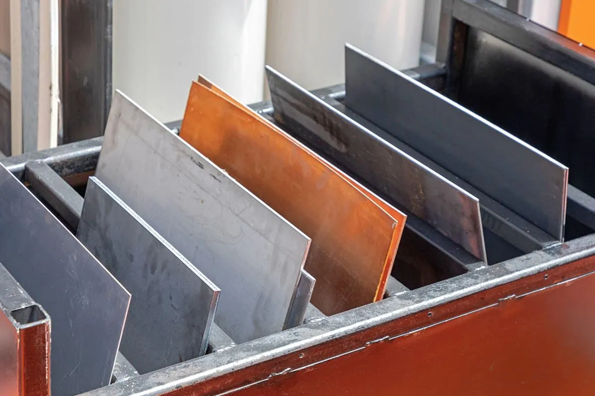
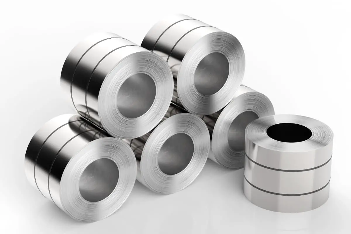
Sheet metal refers to steel plates with thicknesses significantly smaller in comparison to their length and width. They have poor resistance to lateral bending and are not suitable for applications subjected to lateral bending loads.
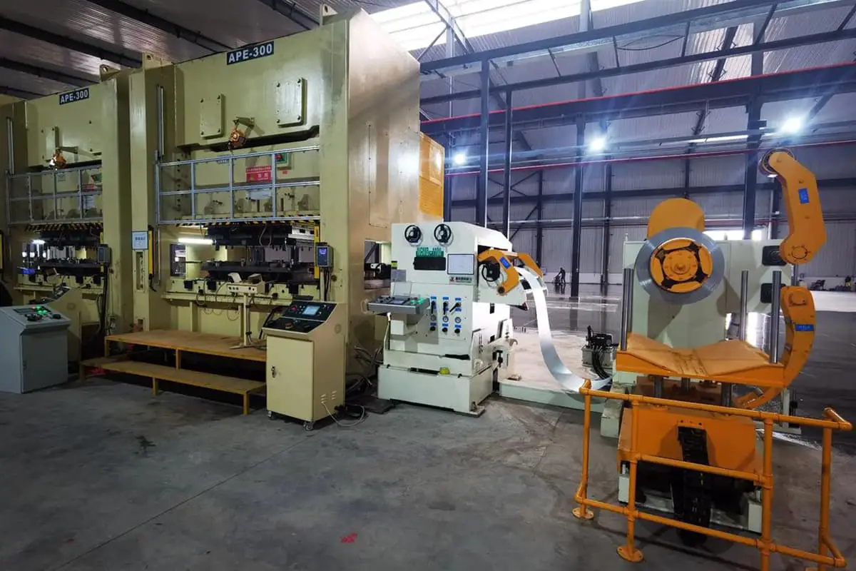
Although sheet metal is made of metal, its specific geometric shape and small thickness give rise to special processing requirements for sheet metal components. There are three main categories of processing techniques related to sheet metal components:
1.Cutting: This includes shearing and punching.
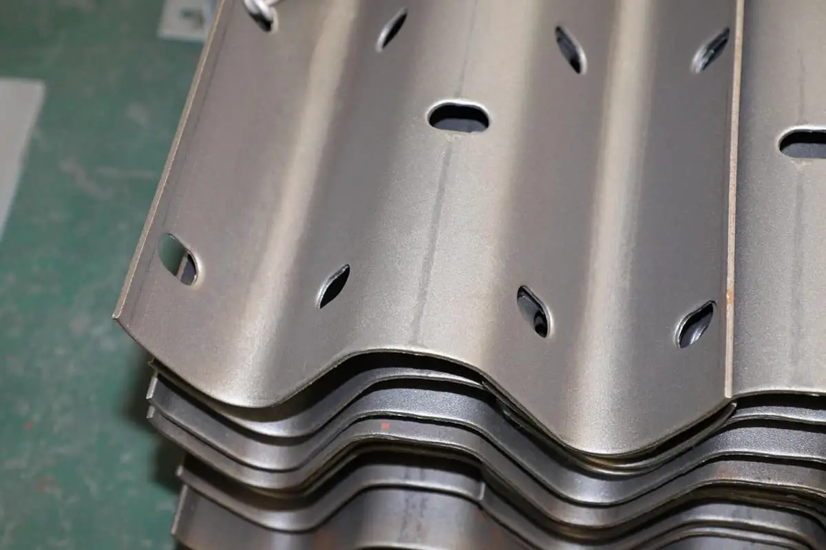
2.Forming: This involves bending, folding, edge rolling, and deep drawing.
3.Joining: This encompasses welding, bonding, and similar techniques.
The structural design of sheet metal components should primarily consider the requirements and characteristics of the processing techniques. Additionally, attention should be paid to the batch size of the components.
Sheet metal components are widely adopted due to several advantages:
1.Ease of deformation, allowing for the manufacture of various component forms using simple processing techniques.
2.Lightweight nature of sheet metal components.
3.Minimal processing requirements due to high surface quality and small dimensional tolerances in the thickness direction, often eliminating the need for surface machining.
4.Ease of cutting and welding, enabling the fabrication of large and complex components.
5.Standardized shapes, facilitating automated processing.
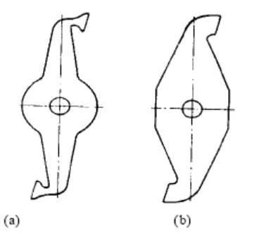
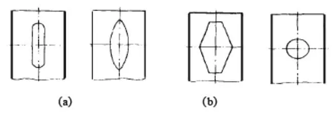
The simpler the geometric shape of the cut surface, the more convenient and straightforward the cutting and forming processes, resulting in shorter cutting paths and reduced material wastage. For instance, straight lines are simpler than curves, circles are simpler than ellipses and other higher-order curves, and regular shapes are simpler than irregular ones (refer to Figures 1, 2, and 3).
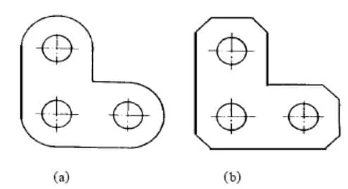
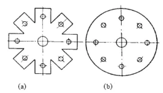
The structure in Figure 4a is only meaningful for large-scale production. Otherwise, it creates complications during the punching and cutting process. Therefore, for small-scale production, the structure shown in Figure 4b is more suitable.
Saving raw materials means reducing manufacturing costs. Scrap materials often end up as waste, so in the design of sheet metal components, it’s essential to minimize scrap. This is particularly effective in large-scale component cutting. Methods to reduce scrap include:
(1) Reducing the distance between adjacent components (refer to Figures 5 and 6).
(2) Clever arrangement (refer to Figure 7).
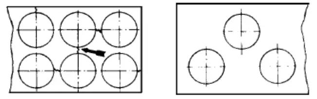
(3) Utilize material from large flat areas for smaller components (refer to Figures 8 and 9).
Due to its small thickness, sheet metal has low stiffness. Sharp corners lack stiffness and should be replaced with rounded corners (refer to Figure 10).
The distance between the two holes, if too small, may lead to the possibility of cracking during cutting (see Figure 11).
The slender and long strip of the plate has low rigidity and is prone to cracking during cutting, especially when the cutting tool is significantly worn. It is evident that such a thin plate structure should be avoided (see Figure 12).
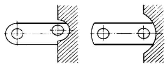
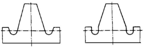
The semi-circular tangent structure shown in Figure 13a is challenging to punch and shear. This is because it requires precise determination of the relative position between the tool and the workpiece.
Accurate measurement and positioning are not only time-consuming but, more importantly, the precision usually cannot meet such high requirements due to tool wear and installation errors.
Once such a structure is processed with slight deviation, it is difficult to guarantee the quality, and the cutting appearance is poor. Therefore, the structure shown in Figure b should be adopted, as it ensures reliable punching and shearing quality.
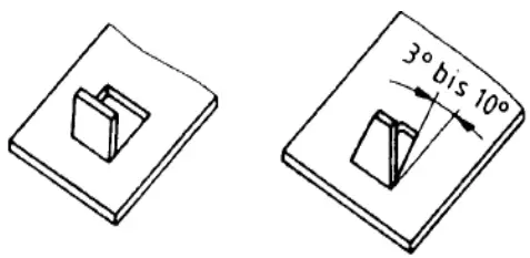
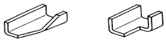
When cutting in the middle of a component, the issue of tool adhesion to the workpiece arises. The solution:
(1) Leave a certain slope
(2) Ensure the cutting surface is connected (see Figure 14 and Figure 15).
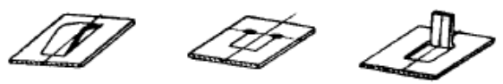
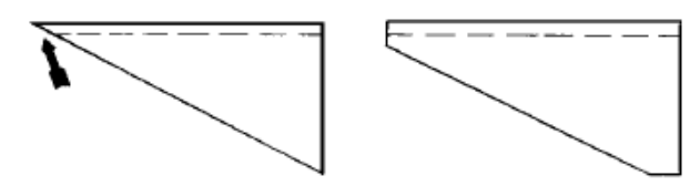
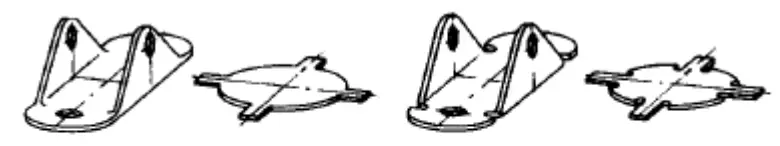
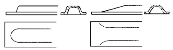
After cutting, thin plates generally undergo further forming processes, such as bending. The bending edges should be perpendicular to the cutting surface; otherwise, the risk of cracking at the intersection increases (see Figure 16, Figure 17, and Figure 18).
When perpendicularity requirements cannot be met due to other constraints, a fillet should be designed at the intersection of the cutting surface and the bent edge, with a radius greater than twice the thickness of the plate (refer to Figure 19).
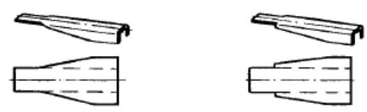
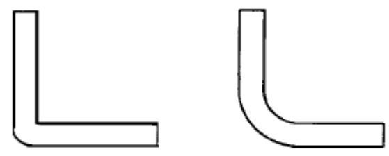
Steep bending requires special tools and is costly. Additionally, small bending radii are prone to cracking and can cause wrinkling on the inner surface (refer to Figure 20, Figure 21).
In the above “Design Guidelines for Sheet Metal Components (Part 1),” we presented seven structural design guidelines for sheet metal components: the simple shape guideline, material-saving guideline, sufficient strength and rigidity guideline, reliable punching guideline, anti-adhesive tool guideline, perpendicular cutting surface for bent edges guideline, and gentle bending guideline.
Building upon the previous content, this article further recommends an additional seven structural design guidelines for sheet metal components.
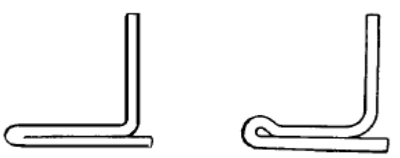
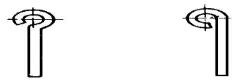
The edges of sheet metal components are often formed into rolled edges, which offer several advantages: (1) enhanced stiffness, (2) prevention of sharp edges, and (3) aesthetic appeal. However, attention should be paid to two aspects of edge rolling: first, the radius should be greater than 1.15 times the thickness of the sheet; second, the edges should not be completely circular, as this makes processing difficult.
The rolled edges shown in Figure 1b and Figure 2b are easier to process compared to those shown in their respective “a” configurations.
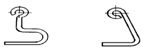
The bent edges and slot hole edges should be at a certain distance from each other, with the recommended value being the bending radius plus twice the wall thickness. The stress state in the bending area is complex and the strength is lower. Slot holes with notch effects should also be excluded from this area. The entire slot hole can be kept away from the bent edge, or the slot hole can span the entire bent edge (refer to Figure 3 and Figure 4).
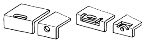
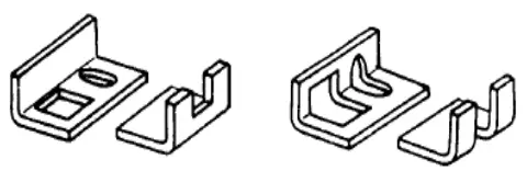
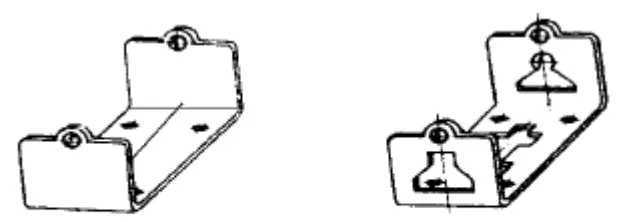
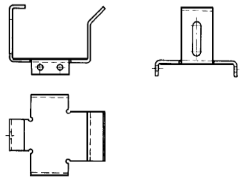
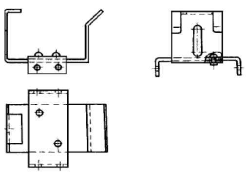
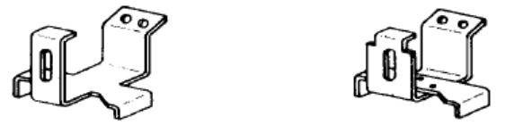
For components with overly complex spatial structures, relying solely on bending forming can be quite challenging. Therefore, it is preferable to simplify the structural design. In cases where complexity is unavoidable, composite components can be used, meaning multiple simple sheet metal components are combined through welding, bolting, or other methods.
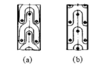
Figure 5 depicts a structure formed purely by bending. Figure 6 represents an improved structure corresponding to Figure 5, which is easier to manufacture than the former. The structure in Figure 7b is easier to manufacture than the one in Figure 7a.
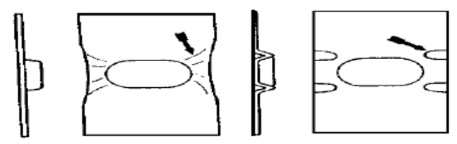
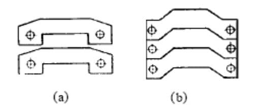
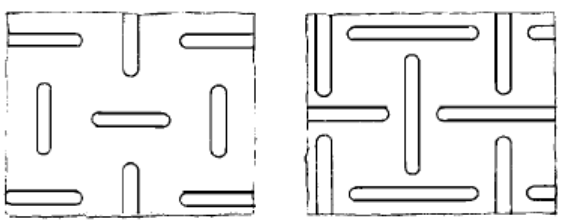
Thin plate structures have the drawback of poor lateral bending stiffness. Large flat plate structures are prone to buckling instability, and further, they may experience bending fractures. Typically, ribbing is used to enhance their stiffness. The arrangement of ribs significantly affects the effectiveness of stiffness enhancement. The basic principle for rib arrangement is to avoid straight-through areas without ribs.
Straight-through areas with low stiffness become the inertia axis for the entire plate surface to buckle and become unstable. Instability always revolves around an inertia axis; therefore, the arrangement of ribs should cut off this inertia axis, making it as short as possible. In the structure shown in Figure 8a, multiple straight-through narrow strips form in the rib-free area, and the overall bending stiffness around these axes is not improved.
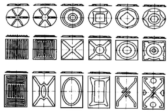
The structure shown in Figure 8b does not have potential connected unstable inertia axes. Figure 9 lists common rib shapes and arrangements, with the stiffness enhancement effect gradually increasing from left to right. Irregular arrangement is an effective method to avoid straight-through areas (refer to Figure 10).
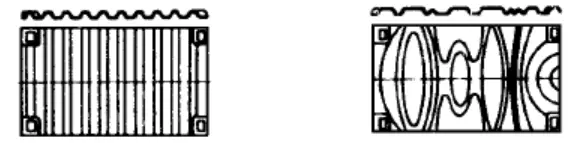
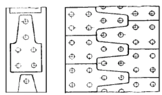
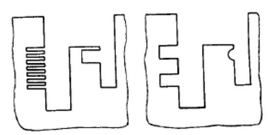
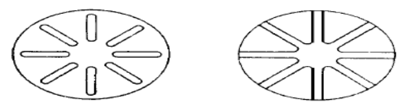
The end point of a groove is a weak link in terms of fatigue strength. If the grooves are connected, some of the end points will be eliminated. Figure 11 depicts a battery box on a truck, which is subjected to dynamic loads. In Figure 11a, fatigue damage occurs at the end of the grooves, whereas in Figure 11b, this issue does not exist.
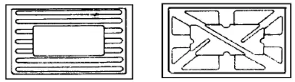
Extend the grooves to the boundary whenever possible (see Figure 13).
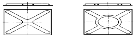
The continuity of the grooves eliminates weak end points. However, at the intersection of the grooves, there should be sufficient space to reduce the mutual influence between the grooves (see Figure 14).
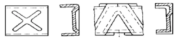
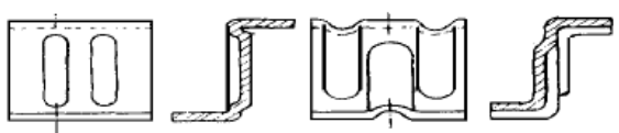
The instability of spatial structures is not limited to a single aspect; therefore, setting grooves only in one plane does not effectively enhance the overall structural stability. For example, in the U-shaped and Z-shaped structures depicted in Figures 15 and 16, instability occurs near the edges. The solution to this issue is to design the grooves in a spatial manner (see structures in Figures 15b and 16b).
When localized deformation on a thin plate is severely hindered, wrinkling occurs. The solution is to place several small grooves near the wrinkles, thereby reducing local stiffness and minimizing deformation hindrance (see Figure 17).