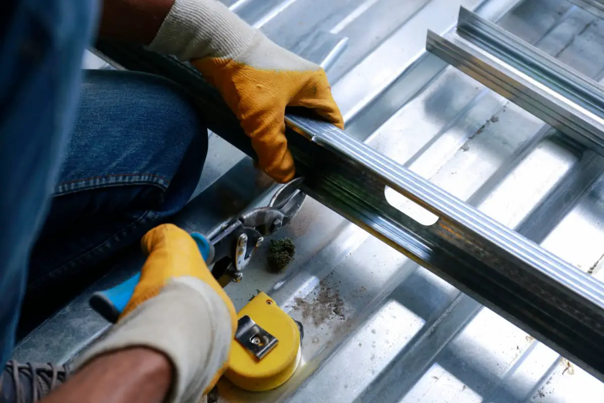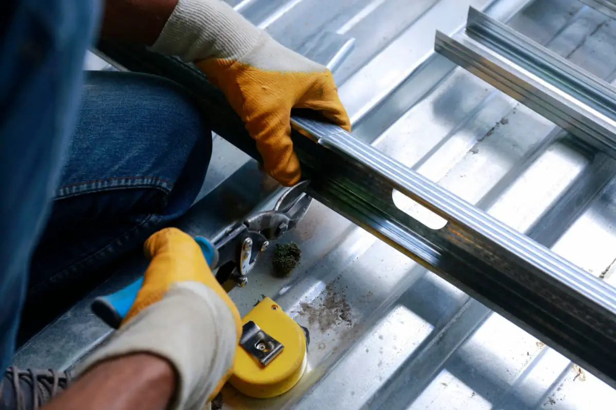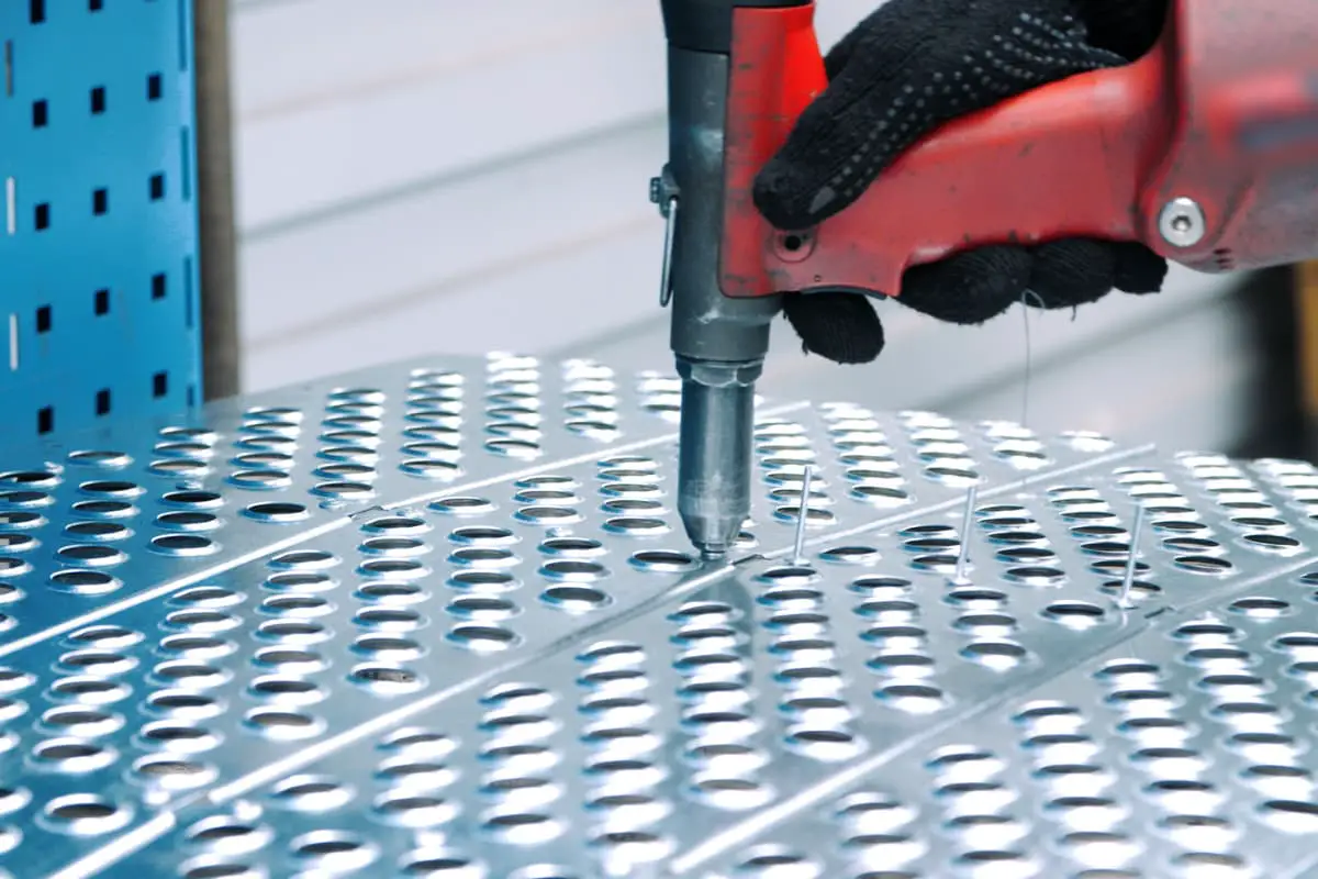
The method of making curved edge parts by thinning and lengthening one side of the blank is called edge expansion, while edge shrinking is the method of making curved parts by shortening the length and increasing the thickness of one side of the blank. Figure 1a shows an outer bent component manufactured by the edge expansion method using angle steel, while Figure 1b shows an inner bent component manufactured using the edge shrinking method.
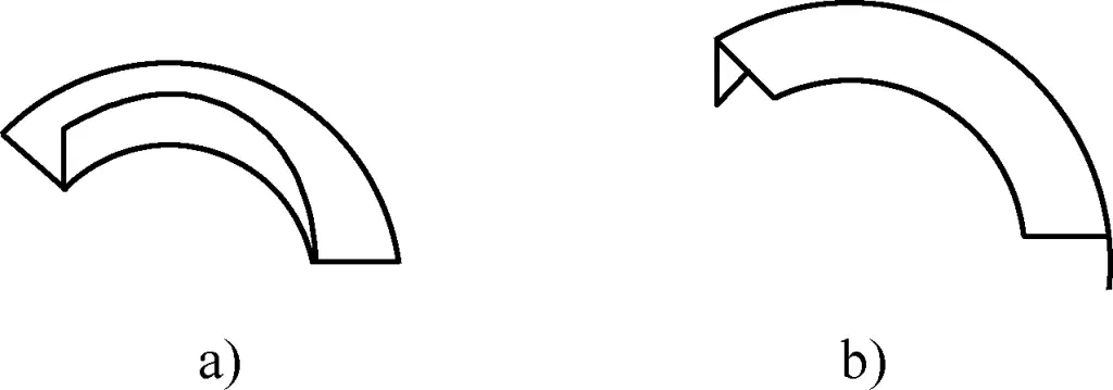
a) Edge Expanding
b) Edge Shrinking
I. Methods of Edge Expanding and Shrinking
The principles of edge expanding and shrinking forming are different, hence their operating methods are not exactly the same.
1. Edge Expanding Method
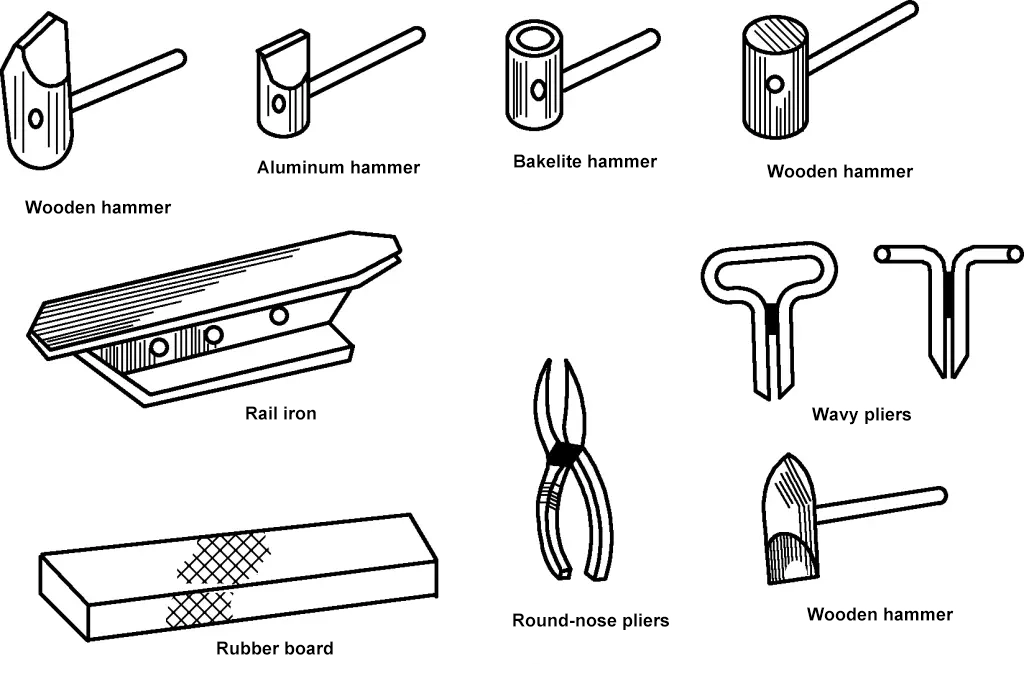
Edge expanding tools include wooden hammers, aluminum hammers, bakelite hammers, iron hammers, rail irons, anvils, platforms, struts, etc., as shown in Figure 2.
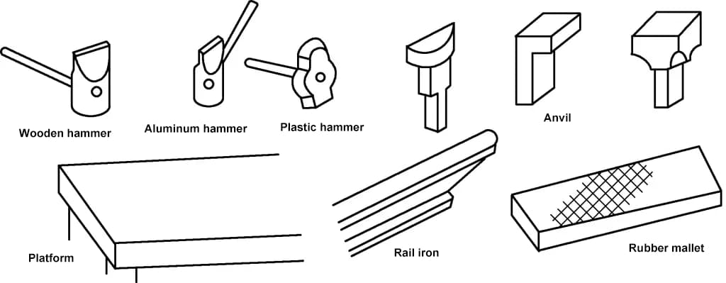
The commonly used method in production is thinning edge expanding. Thinning edge expanding is effective but results in a rough surface and uneven thickness.
When manufacturing the concave curved edge part shown in Figure 1a, a right-angle profile can be used to hammer the material edge on an anvil or platform (see Figure 3), thinning the edge material, increasing its area, extending the curved edge. The closer to the profile edge, the more it extends; the closer to the inner edge, the less it extends. Thus, the straight profile gradually gets hammered into a curved edge part.
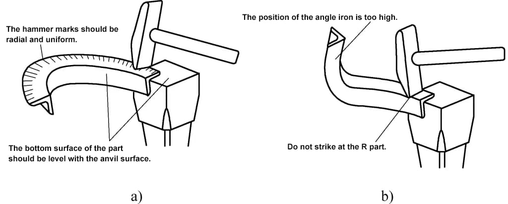
During the hammering operation, the unfolded size of the part must first be calculated. When expanding, the bottom surface of the profile must be kept level with the anvil surface, not too high or too low, otherwise, the profile may warp during the expanding process.
Hammer marks should be even and radiate outward, covering 3/4 of the bend’s width, and not hammering along the R-section of the profile. The hammering should be within the curved area, and for corner parts with straight sections, you should not hammer within the straight area. During expanding, the material may undergo work hardening. If it becomes hard, annealing is needed; otherwise, continued hammering may cause cracking.
During the operation, constantly check the shape with a template or measuring tool. Once the desired shape is achieved, proceed with finishing, straightening, and fine machining.
2. Edge Shrinking Method
Edge shrinking tools include wooden hammers, aluminum hammers, bakelite hammers, iron hammers, rail irons, corrugated pliers, and round-nose pliers, as shown in Figure 4.
In production, the commonly used method is shrinking with corrugated pliers. During operation, use corrugated pliers to form pleated corrugations at the material’s edge; the pleats should be dense and uniform.
If the blank is thick, it can be placed on hardwood and struck with a chopping hammer to create pleats, achieving the desired curvature. Then, while preventing the pleats from straightening and returning, level them on rail iron using a wooden hammer (see Figure 5a). Corrugated pliers can be welded using 8-10mm steel wire bent, and the surface should be smooth to avoid scratching the workpiece surface. The pleat shapes formed should be reasonable (see Figure 5b).

II. Calculation of Unfolded Size for Edge Expanding and Shrinking
Due to the different deformations occurring in edge expanding and shrinking, the calculation of the unfolded size also differs.
1. Calculation of Unfolded Size for Edge Expanding Parts
The unfolded width of the semi-circular part in Figure 6 can be calculated using the calculation formula for the unfolded length of bent profiles.

B=a+b-(r/2+t)
In the formula
- B – Unfolded material width (mm);
- a, b – Edge expanding width (mm);
- r – Corner radius (mm);
- t – Material thickness (mm).
The unfolded length is calculated using the arc length at half the width of edge expansion b, due to the different degrees of material expansion in various parts of the expanding plane. The outer edge thins more and expands more, while the inner edge thins less and expands less.
L=π(R+b/2)
In the formula
- L – Unfolded material length (mm);
- R – Bend radius of the part (mm);
- b – Width of one side of edge expansion (mm).
The unfolded width of the right-angle part shown in Figure 7 is the same as the above formula. The unfolded length L equals the sum of the straight and curved parts, i.e.,
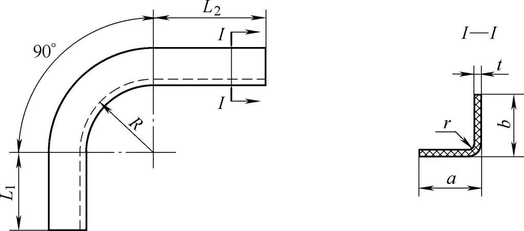
L=L1+L2+ π/2(R +b/2)
In the formula
- L1, L2 – Length of the straight parts (mm);
- R – Bend radius of the part (mm);
- b – Width of one side of edge expansion (mm).
2. Calculation of Unfolded Size for Edge Shrinking Parts
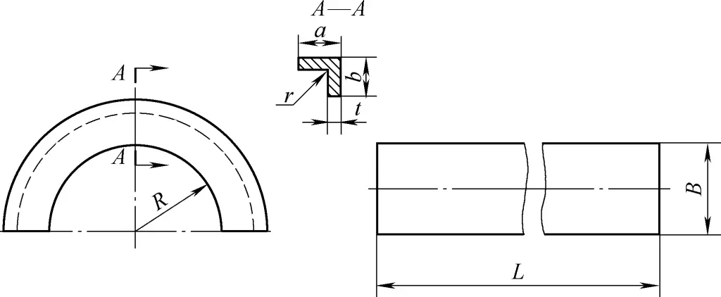
The unfolded material for angle steel shrunk into semi-circular parts, as shown in Figure 8, is calculated using the following formula:
B=a+b-(r/2+t)
L=π(R+b)
In the formula
- L – Unfolded material length (mm);
- B – Unfolded material width (mm);
- a, b – Bend width (mm);
- R – Bend radius of the part (mm).
- r-radius of curvature (mm);
- t-material thickness (mm).
As shown in Figure 9, the angle trimming part into a right-angle shape has the same unfolded width as the above formula. The unfolded length L is calculated as follows:
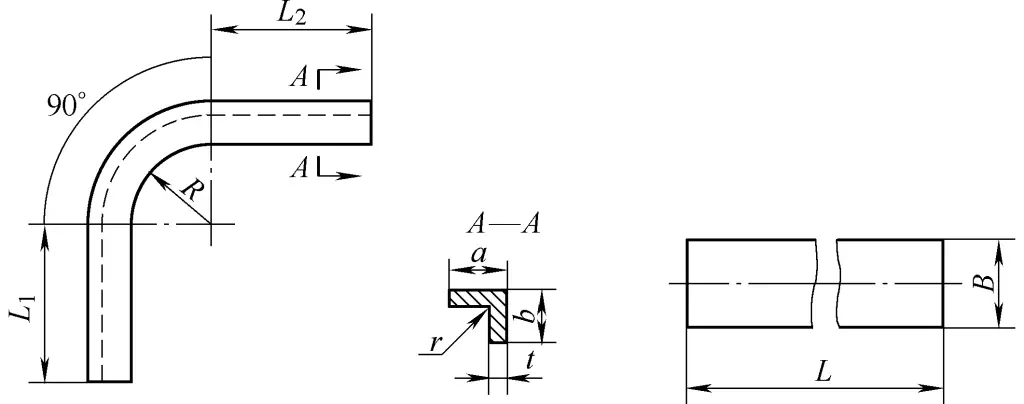
L=L1+L2+π/2(R+b)
In the formula
- L1, L2 – are the lengths of the straight parts (mm);
- R-radius of bending part (mm);
- b-width of one side of the allowance (mm).

