Bending allowance table
| Plate thickness/V-groove width | Cold rolled steel plate, galvanized steel plate or aluminum zinc coated steel plate | |||||||||||||
|---|---|---|---|---|---|---|---|---|---|---|---|---|---|---|
| 0.6 | 0.8 | 1.0 | 1.2 | 1.5 | 20 | 2.5 | 3.0 | 3.5 | .0 | 4.5 | 5.0 | Minimum size | remarks | |
| V4 | 0.9 | 1.4 | 2.8 | When the part graphic size is marked with a negative tolerance, the bending allowance value can be increased. For example, the red part in the table can be increased by at least: 2.8:2.82,3.4:3.43 or 3.44, 4.5:4.6, 5.5:5.6 | ||||||||||
| V6 | 1.5 | 1.7 | 2.0 | 4.5 | ||||||||||
| V7 | 1.8 | 2.1 | 2.4 | 5 | ||||||||||
| V8 | 1.9 | 2.2 | 2.5 | 5.5 | ||||||||||
| V10 | 2.1 | 2.3 | 2.7 | 7 | ||||||||||
| V12 | 2.2 | 2.5 | 2.8 | 3.4 | 8.5 | |||||||||
| V14 | 3.5 | 3.8 | 6.4 | 6.8 | 10 | |||||||||
| V16 | 3.1 | 3.8 | 4.5 | 5.0 | 11 | |||||||||
| V18 | 3.3 | 4.0 | 13 | |||||||||||
| V20 | 4.0 | 4.9 | 5.1 | 6.6 | 7.2 | 7.8 | 14 | |||||||
| V25 | 4.4 | 5.0 | 5.5 | 6.8 | 7.8 | 8.3 | 17.5 | |||||||
| V32 | 5.0 | 5.5 | 6.1 | 8.7 | ||||||||||
Double-layer bending allowance table
Cold rolled steel plate, galvanized steel plate or aluminum zinc coated steel plate
| Angle | Mold slot width | 90° | Internal bending angle | External bending angle | 180° |
|---|---|---|---|---|---|
| Plate thickness mm | |||||
| 1.5 | V10 | 3 | 3.2 | 4.1 | 0.75 |
| 2.0 | V12 | 3.84 | 3.7 | 4.6 | 1.0 |
| 2.5 | V16 | 45 | 4.8 | 6.1 | 1.25 |

Bending allowance table for different bending angles
| Plate thickness mm | 30 | 45° | 60° | 120° | 135 | 145° |
|---|---|---|---|---|---|---|
| 1.0 | 0.35 | 0.7 | 1.1 | 1.0 | 0.6 | 0.4 |
| 1.2 | 0.4 | 0.8 | 1.2 | 1.0 | 0.6 | 0.4 |
| 1.5 | 0.5 | 1.0 | 1.6 | 1.4 | 0.9 | 0.6 |
| 2.0 | 0.6 | 1.2 | 2.0 | 1.7 | 1.1 | 0.7 |
| 2.5 | 0.8 | 1.6 | 2.6 | 2.2 | 1.4 | 0.85 |
| 3.0 | 1.0 | 2.2 | 3.4 | 2.8 | 2.0 | 1.2 |
| 4.0 | 3.7 | 2.4 | 1.4 |
1. Parts process unfolding design example
1.1 Example of right-angle edge bending process unfolding drawing.
1.1.1 Example of one-bend unfolding drawing and calculation formula

- A, B – length of the workpiece bend
- P’ – bending allowance for bend (bending allowance: subtract a allowance for each bend)
- R – bend radius (usually equal to the thickness of the plate)
- T – material thickness
Unfolding length: L = A + B – P’, i.e., L = 25 + 65 – 5.5 = 84.5
According to Table 1: For a plate thickness of 3 mm, the V25 lower die should be used, with a bending allowance of 5.5.
Note: According to Table 1, different lower dies have different bending allowances, and different plate thicknesses have different bending allowances.
1.1.2 Example of two-bend unfolding drawing and calculation formula

- A(A1), B – length of the workpiece bend
- P – bending allowance for bend (bending allowance: subtract an allowance for each bend)
- R – bend radius (usually equal to the thickness of the plate)
- T – material thickness
Unfolding length: L = A + T + B – 2xP’, i.e., L = 50 + 2 + 50 – 2×3.4 = 95.6
According to Table 1: For a plate thickness of 2 mm, the V12 lower die should be used, with a bending allowance of 3.4.
Note: According to Table 1, different lower dies have different bending allowances, and different plate thicknesses have different bending allowances.
1.1.3. Example of three-bend unfolding drawing and calculation formula

- A(A1), B(B1) – length of the workpiece bend
- P – bending allowance for bend (bending allowance: subtract an allowance for each bend)
- R – bend radius (usually equal to the thickness of the plate)
- T – material thickness
Unfolding length: L = A + T + B + T – 3xP’, i.e., L = 50 + 2 + 90 + 2 – 3×3.4 = 133.8
According to Table 1: For a plate thickness of 2 mm, the V12 lower die should be used, with a bending allowance of 3.4.
Note: According to Table 1, different lower dies have different bending allowances, and different plate thicknesses have different bending allowances.
1.1.4. Example of four-bend unfolding drawing and calculation formula

- A, B(B1) – length of the workpiece bend
- P – bending allowance for bend (bending allowance: subtract an allowance for each bend)
- R – bend radius (usually equal to the thickness of the plate)
- T – material thickness
Unfolding length: L = A + A + B + T + T – 4xP’, i.e., L = 25 + 25 + 100 + 1.5 + 1.5 – 4×2.8 = 141.8
According to Table 1: For a plate thickness of 1.5 mm, the V12 lower die should be used, with a bending allowance of 2.8.
Note: According to Table 1, different lower dies have different bending allowances, and different plate thicknesses have different bending allowances.
1.1.5. Example of six-bend unfolding drawing and calculation formula

- A(A1), B(B1) – length of the workpiece bend
- P’ – bending allowance for bend (bending allowance: subtract an allowance for each bend)
- R – bend radius (usually equal to the thickness of the plate)
- T – material thickness
Unfolding length: L = A + T + A + T + B + B1 + B1 – 6xP’, i.e., L = 50 + 1.5 + 50 + 1.5 + 150 + 20 + 20 – 6×2.8 = 276.2
According to Table 1: For a plate thickness of 1.5 mm, the V12 lower die should be used, with a bending allowance of 2.8.
Note: According to Table 1, different lower dies have different bending allowances, and different plate thicknesses have different bending allowances.
1.2.1. Examples and Calculation Formulas for 180° Bending Unfolding.

- A, B – length of the workpiece bend
- P – flattening radius bending allowance
- R – bend radius (usually equal to the thickness of the plate)
- T – material thickness
Unfolding length: L = A + B – P’, i.e., L = 25 + 65 – 1 = 89
According to Table 2: For a plate thickness of 2 mm, the V12 lower die should be used, with a bending allowance of half the plate thickness.
Note: According to Table 2, different lower dies have different bending allowances, and different plate thicknesses have different bending allowances.
1.2.2. Examples and Calculation Formulas for Double-layer Bending Unfolding.

- A, B – length of the workpiece bend
- P1 – bending allowance for internal corners
- P2 – bending allowance for external corners
- R – bend radius (usually equal to the thickness of the plate)
- T – material thickness
Unfolding length: L1 = (A-1.5) + (B-1.5) – P1, i.e., L1 = (65-1.5) + (25-1.5) – 3.2 = 83.8
L2 = A + B – P2, i.e., L2 = 65 + 25 – 4.1 = 85.9
L = L1 + L2 – T/2, i.e., L = 83.8 + 85.9 – 0.75 = 168.95
According to Table 2: For a plate thickness of 1.5 mm, the V12 lower die should be used, with a bending allowance of 3.2 for internal corners, 4.1 for external corners, and 0.75 for a 180° angle.
Note: According to Table 2, different lower dies have different bending allowances, and different plate thicknesses have different bending allowances.
1.2.3. Examples and Calculation Formulas for Double-layer Bending Unfolding.

- A(A1), B1B2- length of the workpiece bend
- P1 – bending allowance for internal angle
- P2 – bending allowance for external angle
- P3 – 90° bending allowance
- R – bend radius (usually equal to the thickness of the plate)
- T – material thickness
- P4 – 180°bending allowance
Unfolding length: L1 = A + B1 – P2, i.e., L1 = 75 + 29 – 4.6 = 99.4
L2 = (A1 – T) + (B1 – T) – P1, i.e., L2 = (37 – 2) + (29 – 2) – 3.7 = 58.7
L3 = L1 + L2 – P3, i.e., L3 = 99.4 + 58.3 – 1 = 156.7
L = 25.5 + L3 – P1, i.e., L = 25.5 + 156.7 – 3.84 = 178.36
According to Table 2: For a plate thickness of 1.5 mm, the V12 lower die should be used, with an internal angle bending allowance of 3.2, an external angle bending allowance of 4.1, and a 180° bending allowance of 0.75.
Note: According to Table 2, different lower dies have different bending allowances, and different plate thicknesses have different bending allowances.
1.2.4. Examples and Calculation Formulas for Double-layer Bending Unfolding.

- A, A1, A2, B1, B2, L, L1, L2, L3 – length of the workpiece bend
- P1 – bending allowance for internal angle
- R – bend radius (usually equal to the thickness of the plate)
- T – material thickness
- P2 – bending allowance for external angle
Unfolding length: L1 = (A1-T) + (B2-T) – P1, i.e., L1 = (35-2) + (34-2) – 3.7 = 61.3
L2 = (B1-T) + (A2-T) – P1, i.e., L2 = (50-2) + (34-2) – 3.7 = 76.3
L3 = A + B1 + B2 – 2 x P2, i.e., L3 = 70 + 35 + 50 – 2 x 4.6 = 145.8
L = L1 + L2 + L3 – 2 x P3, i.e., L = 61.3 + 75.3 + 145.8 – 2 x 1 = 281.4
According to Table 2: For a plate thickness of 2 mm, the V12 lower die should be used, with an internal angle bending allowance of 3.7, an external angle bending allowance of 4.6, and a 180° bending allowance of 1.
Note: According to Table 2, different lower dies have different bending allowances, and different plate thicknesses have different bending allowances.
1.3.1. Examples and Calculation Formulas for Special Angle Bending Unfolding.
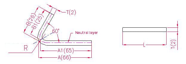
- A(A1), B(B1) – length of the workpiece bend
- P – bending allowance for one-bend angle (varies with the angle)
- R – bend radius (usually equal to the thickness of the plate)
- T – material thickness
Unfolding length: L = (A-T) + (B-T) – P’ = A1 + B1 – P’, i.e., L = (66-1) + (26-1) – 2 = 65+25-2 = 88
According to Table 3: For a plate thickness of 2 mm, the V12 lower die should be used, and the bending allowance for a 60° angle is 2.
Note: According to Table 3, the neutral layer should be used as the bending length and width.
1.3.2. Examples and Calculation Formulas for Step Pressing Unfolding.

- A, B – length of the workpiece bend
- R – bend radius (usually equal to the thickness of the plate)
- T – material thickness
Unfolding length: L = A + 1
Note: When the step is equal to two plate thicknesses, add 0.5 for each step, and add 1 for two steps.
1.3.3. Examples and Calculation Formulas for Special Angle Unfolding.

- A(A1A2A3A4), B – length of the workpiece bend
- P – bending allowance for a 135° angle
- R – bend radius (usually equal to the thickness of the plate)
- T – material thickness
Unfolding length: L = A1 + A2 + A3 + A2 + A4 – P – P
Note: For bending with steps, just subtract two allowances.
According to Table 3: For a plate thickness of 2 mm, the V12 lower die should be used, and the bending allowance for a 135° angle is 1.1.
1.3.4. Examples and Calculation Formulas for Special Angle Unfolding.

- A(A1A2), B(B1B2) – length of the workpiece bend
- P1 – bending allowance for a 120° angle
- P2 – bending allowance for a 145° angle
- P3 – 90° bending allowance
- R – bend radius (usually equal to the thickness of the plate)
- T – material thickness
Note: When the dimension is marked on the outline, it needs to be converted to the neutral layer size when calculating the unfolding length.
Unfolding length: L = A11 + B11 + B21 + A21 – P1 – P2 – P3, i.e., L = 80 + 50 + 103 + 70 – 1.7 – 0.7 – 3.4 = 297.2
According to Table 3: For a plate thickness of 2 mm, the V12 lower die should be used, with a bending allowance of 1.7 for a 120° angle, 0.7 for a 145° angle, and 3.4 for a 90° angle.
Note: According to Table 3, different lower dies have different bending allowances, and different plate thicknesses have different bending allowances.
1.4.1. Examples and Calculation Formulas for Ordinary Flanging Unfolding.

- A, B, C – length, width, and height of the workpiece bend
- P – bending allowance
- R – bend radius (usually equal to the thickness of the plate)
- H(H1), L(L1) – unfolding length of each side
- T – material thickness
- D – bending process gap (usually between 0 and 0.5)
Unfolding length: L1 = A, i.e., L1 = 27
L = A + C – P, i.e., L = 27 + 9 – 3.4 = 32.6
H1 = B – T – D, i.e., H1 = 22 – 2 – 0.2 = 19.8 (Note: D is taken as 0.2)
H = B + C – P, i.e., H = 22 + 9 – 3.4 = 27.6
According to Table 1: For a plate thickness of 2 mm, the V12 lower die should be used, with a bending allowance of 3.4.
Note: According to Table 1, different lower dies have different bending allowances, and different plate thicknesses have different bending allowances.
1.4.2. Examples and Calculation Formulas for Ordinary Door Flanging Unfolding.
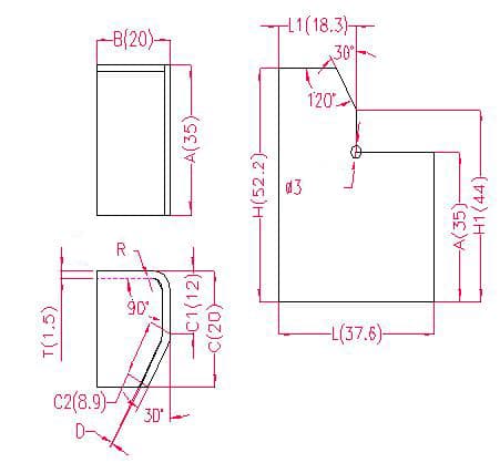
- A, B, C – length, width, and height of the workpiece bend
- L(L1), H(H1) – unfolding length of each side
- P – bending allowance for a 90° angle
- P1 – bending allowance for a 30° angle
- R – bend radius (usually equal to the thickness of the plate)
- T – material thickness
- D – bending process gap (usually between 0 and 0.5)
Unfolding length: L1 = B – T – D, i.e., L1 = 20 – 1.5 – 0.2 = 18.3
L = B + C1 + C2 – P – P1, i.e., L = 20 + 12 + 8.9 – 2.8 – 0.5 = 37.6
H1 = C1 + A – P – D, i.e., H1 = 12 + 35 – 2.8 – 0.2 = 44 (Note: D is taken as 0.2)
H = A + C – P, i.e., H = 35 + 20 – 2.8 = 52.2
According to Table 1: For a plate thickness of 1.5 mm, the V12 lower die should be used, with a bending allowance of 2.8 for a 90° angle and 0.5 for a 30° angle.
Note: According to Table 1, different lower dies have different bending allowances, and different plate thicknesses have different bending allowances.
1.4.3. Examples and Calculation Formulas for Ordinary Flanging Bending and Unfolding.
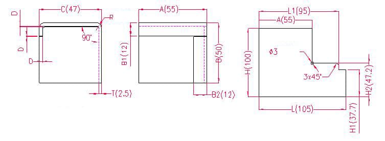
- A, B, C – length, width, and height of the workpiece bend
- P – bending allowance
- R – bend radius (usually equal to the thickness of the plate)
- T – material thickness
- D – bending process gap (usually between 0 and 0.5)
Unfolding length: H1 = B – B1 – D, i.e., H1 = 50 – 12 – 0.3 = 37.7 (Note: D is taken as 0.2)
H2 = B – T – D, i.e., H2 = 50 – 2.5 – 0.3 = 47.2
H = B + C + B1 – 2xP, i.e., H = 50 + 47 + 12 – 2×4.5 = 100
L1 = A + C – T – D – P, i.e., L1 = 55 + 47 – 2.5 – 0.3 – 4.5 = 94.7
L = A + C+ B2 – 2xP, i.e., L = 55 + 47 + 12 – 2×4.5 = 105
According to Table 1: For a plate thickness of 2.5 mm, the V16 lower die should be used, with a bending allowance of 4.5.
Note: According to Table 1, different lower dies have different bending allowances, and different plate thicknesses have different bending allowances.

