Stamping Defects: Effective Fixes and Tips
Why do stamped metal parts often suffer from cracks, scratches, or unclear edge lines? Understanding these common defects is crucial…
In this blog, we explore the common defects found in bent parts and how to eliminate them. You’ll learn about the causes of these imperfections and practical tips to improve the accuracy and quality of your metal bending projects. Whether you’re dealing with cracks or surface scratches, this guide provides the insights needed to achieve flawless bent components.
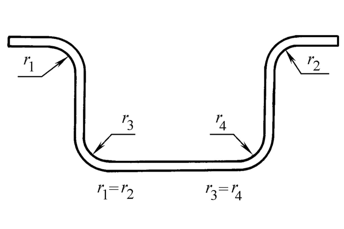
Table 1 lists the common defects of bent parts and their causes and elimination methods. The accuracy of bent parts mainly refers to the accuracy and stability of their shape and size.
Table 1 Common defects of bent parts and their elimination methods
| Defects | Schematic | Causes | Elimination methods |
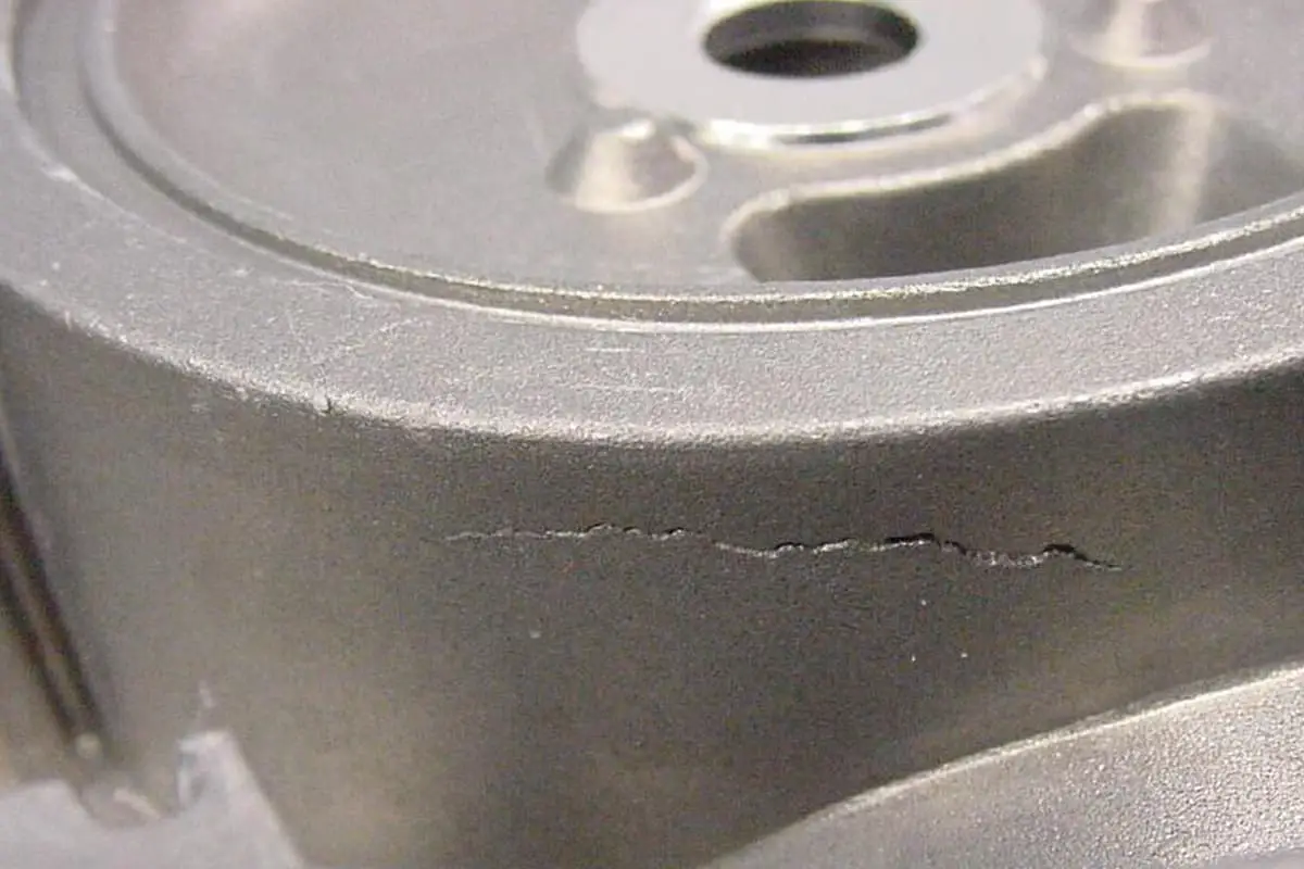
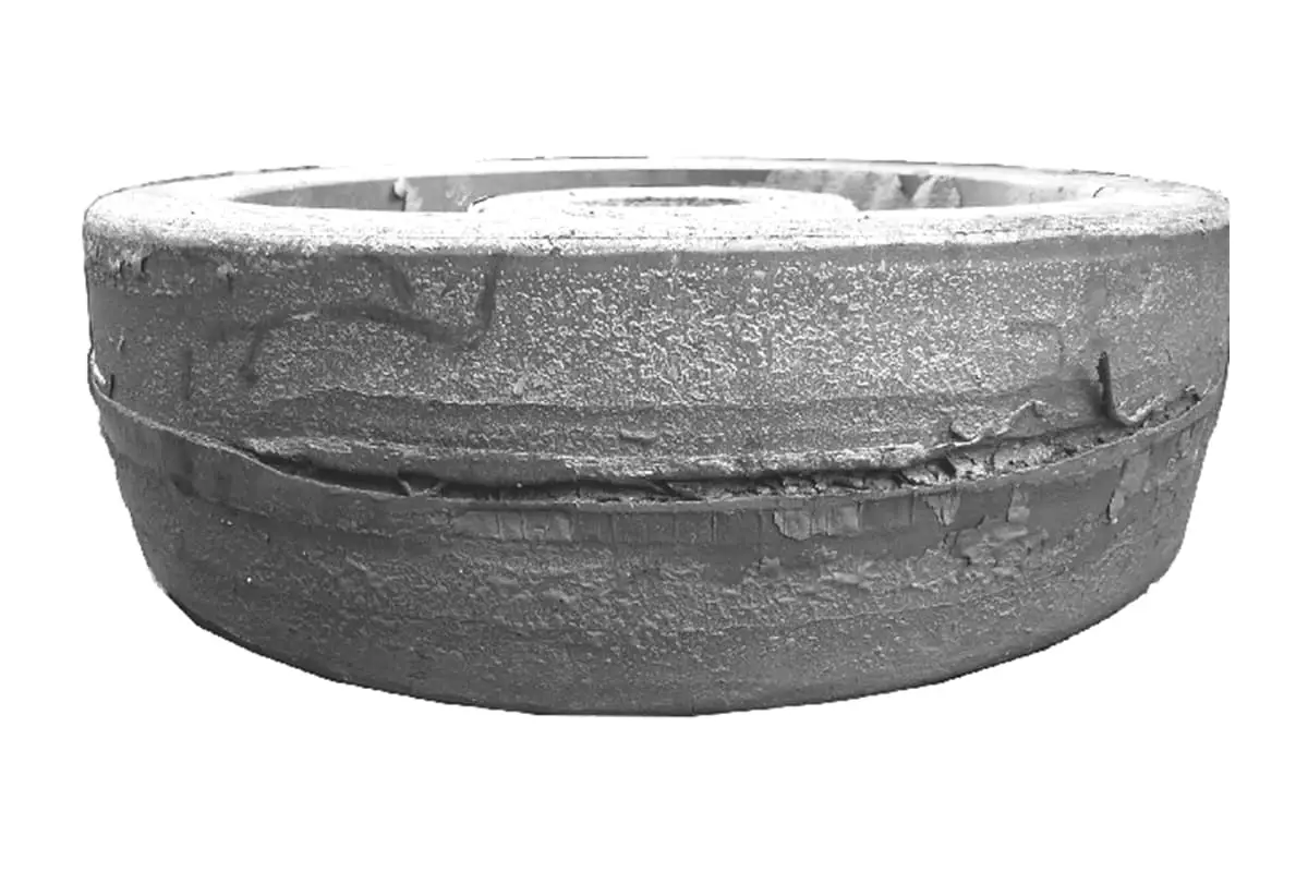
| Crack | 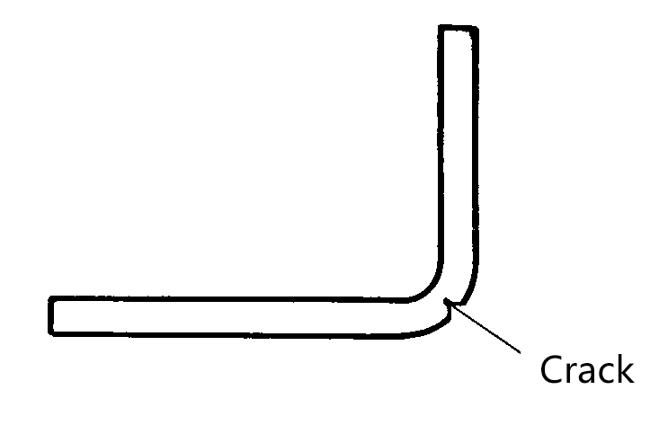 | The bending radius of the punch is too small The burr side of the blank is on the outside of the bend The plasticity of the plate is low The hardening layer of the blank is too large when cutting | Appropriately increase the radius of the punch fillet Place the burr side on the inside of the bend Use materials that have been annealed or have better plasticity The bending line is perpendicular to the fiber direction or at a 45° angle |
| The bottom is uneven | 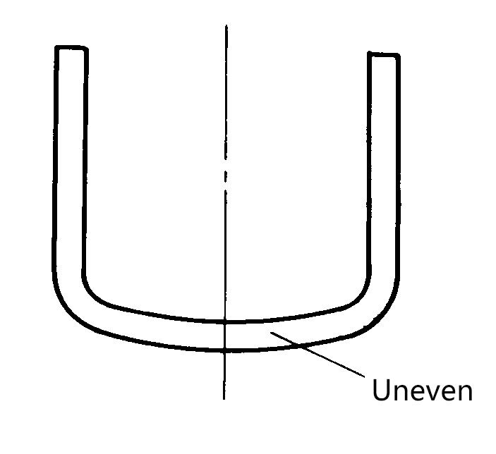 | During bending, the plate material does not press tightly against the bottom of the punch | Use a mold with a pressure pad, which applies sufficient pressure to the blank at the start of bending |
| Warping | 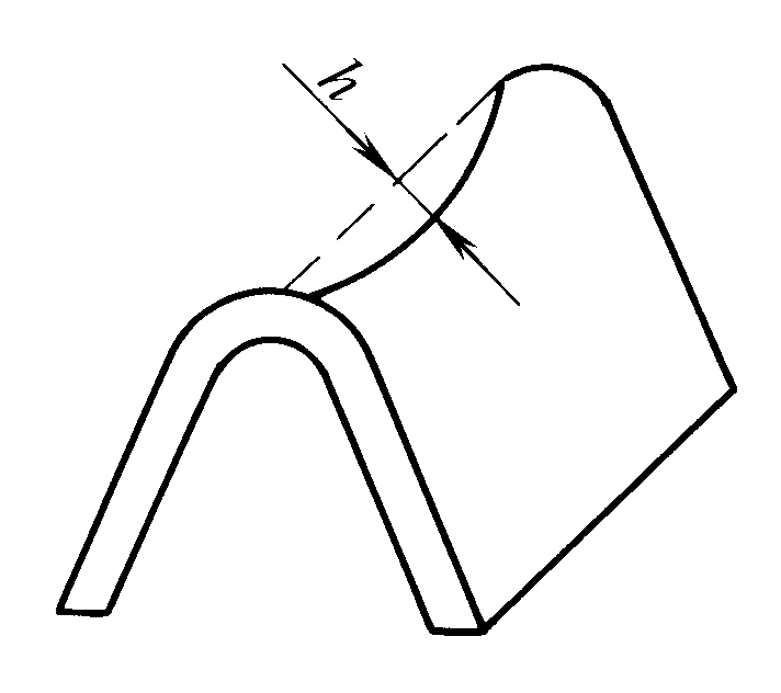 | Due to the strain state in the deformation zone, the lateral strain (along the direction of the bending line) is compressive strain on the outside of the neutral layer and tensile strain on the inside of the neutral layer, thus lateral warping is formed | Use corrective bending, increase the unit area pressure according to the amount of warping to correct the convex and concave dies |
| Misalignment of holes | 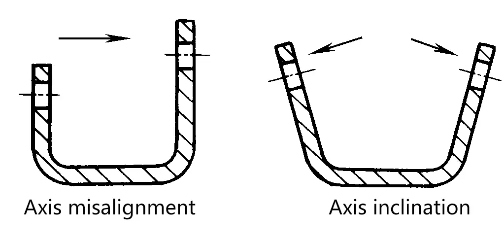 | Sliding occurred in the blank during bending, hence causing a shift in the centerline of the hole The springback after bending causes the centerline of the hole to tilt | The blank must be accurately positioned to ensure consistent bending heights on both sides Set positioning pins or pressing top plates to prevent the blank from moving Reduce the workpiece springback |
| The heart bending line and the centerlines of the two holes are not parallel | 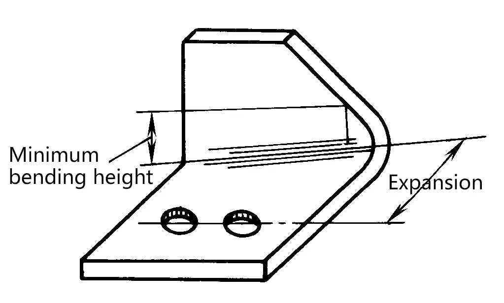 | The bending height is less than the minimum bending height, and the part below the minimum bending height shows opening | When designing the workpiece, ensure that it is greater than or equal to the minimum bending height When the workpiece is less than the minimum bending height, the part that is less than the minimum bending height can be removed before bending |
| Surface scratches | 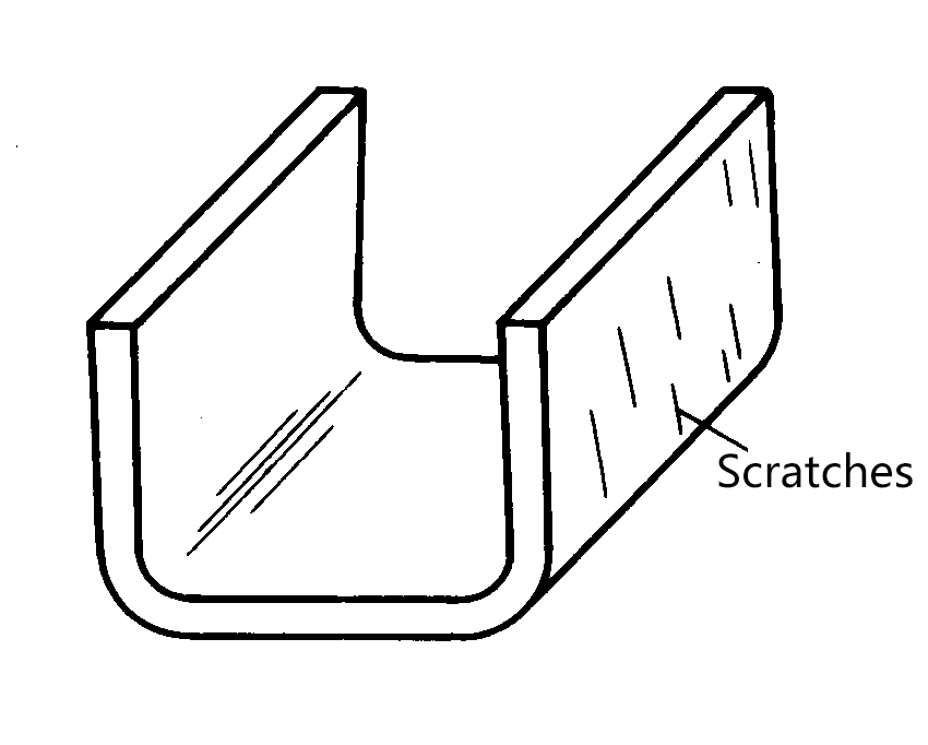 | Metal particles adhere to the surface of the working part The radius of the die corner is too small The gap between the punch and die is too small | Appropriately increase the radius of the die corner Improve the surface finish of the punch and die Use a reasonable gap value between the punch and die Clean part of the surface dirt from the work |
| Dimensional deviation |  | When the blank slides towards the concave mold, the friction resistance on both sides is not equal, resulting in dimensional deviation. This is significant in the bending of asymmetrical shaped parts | Molds that use a pressing top plate The blank must be accurately positioned in the mold Where possible, use symmetrical bending |
| Hole deformation | 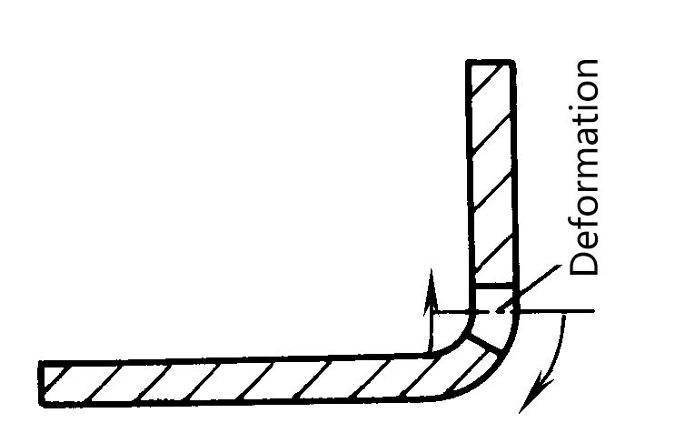 | The edge of the hole is too close to the bending line, with compression deformation on the inside of the neutral layer and tensile deformation on the outside, hence the hole is deformed | Ensure the distance from the edge of the hole to the center of the bending radius r is greater than a certain value Set auxiliary holes at the bending parts to reduce bending deformation stress |
| Change in bending angle | 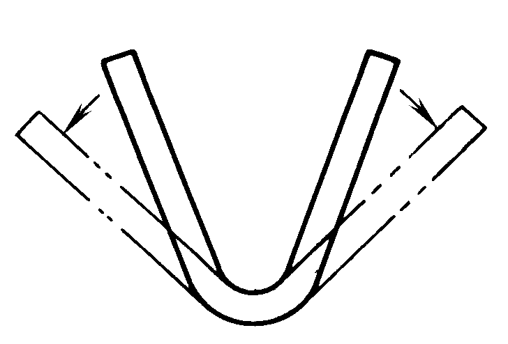 | Plastic bending is accompanied by elastic deformation. When the bent workpiece is removed from the mold, elastic recovery occurs, causing the bending angle to change. | Corrective bending is used instead of free bending to correct the angle of the punch and die with a predetermined springback angle. |
| Bulging at the bending end | 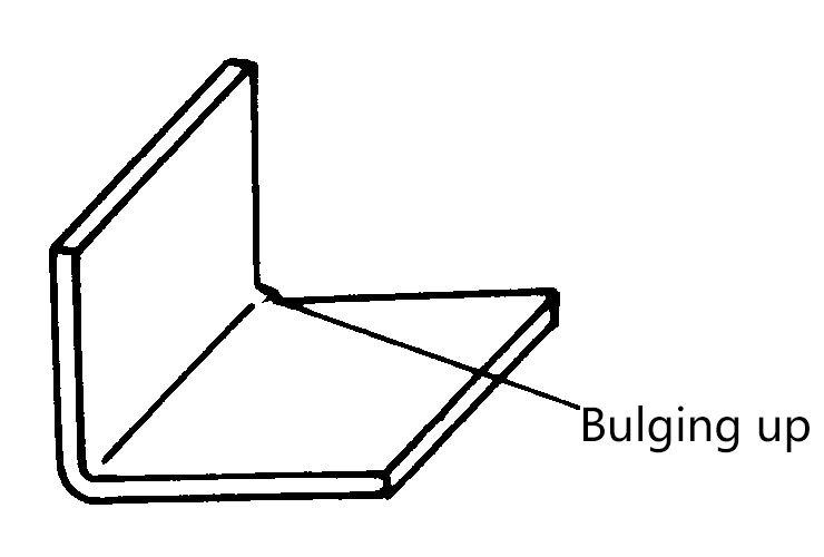 | During bending, the metal layer on the inside of the neutral layer is compressed longitudinally and shortened, while it is elongated in the width direction, hence a protrusion appears on the edge in the width direction, which is more apparent in thick plate bending with a small angle. | Make a round notch at both ends of the bending part in advance to place the burrs on the inside of the bend. |
The main factors affecting the precision of bent parts, in addition to the structure and material factors of the bent parts themselves, are also related to the stamping process and molds and other process factors. Here are the process measures to improve the accuracy of bent parts:
Before preparing the stamping process, the manufacturability of the bent part structure should be reviewed. If there are shapes that are not conducive to bending, they should be discussed with the designers to try to improve them.
When preparing the stamping process, the following points should be mainly considered.
(1) Since the elongation rate of the steel plate in the rolling direction is greater than that perpendicular to the rolling direction, it should be considered to bend as much as possible perpendicular to the rolling direction when cutting the blank. If bending in both directions, cut at an angle (45°) to avoid the bending line being parallel to the rolling direction.
(2) When considering the positioning of the parts, a high-precision, dimensionally stable, and convenient positioning method should be selected, making full use of the shape and holes of the parts themselves for positioning, and if necessary, adding process holes for positioning. For asymmetrically shaped parts, the directionality of positioning should also be considered to prevent the blank (semi-finished product) from being placed in reverse, resulting in waste.
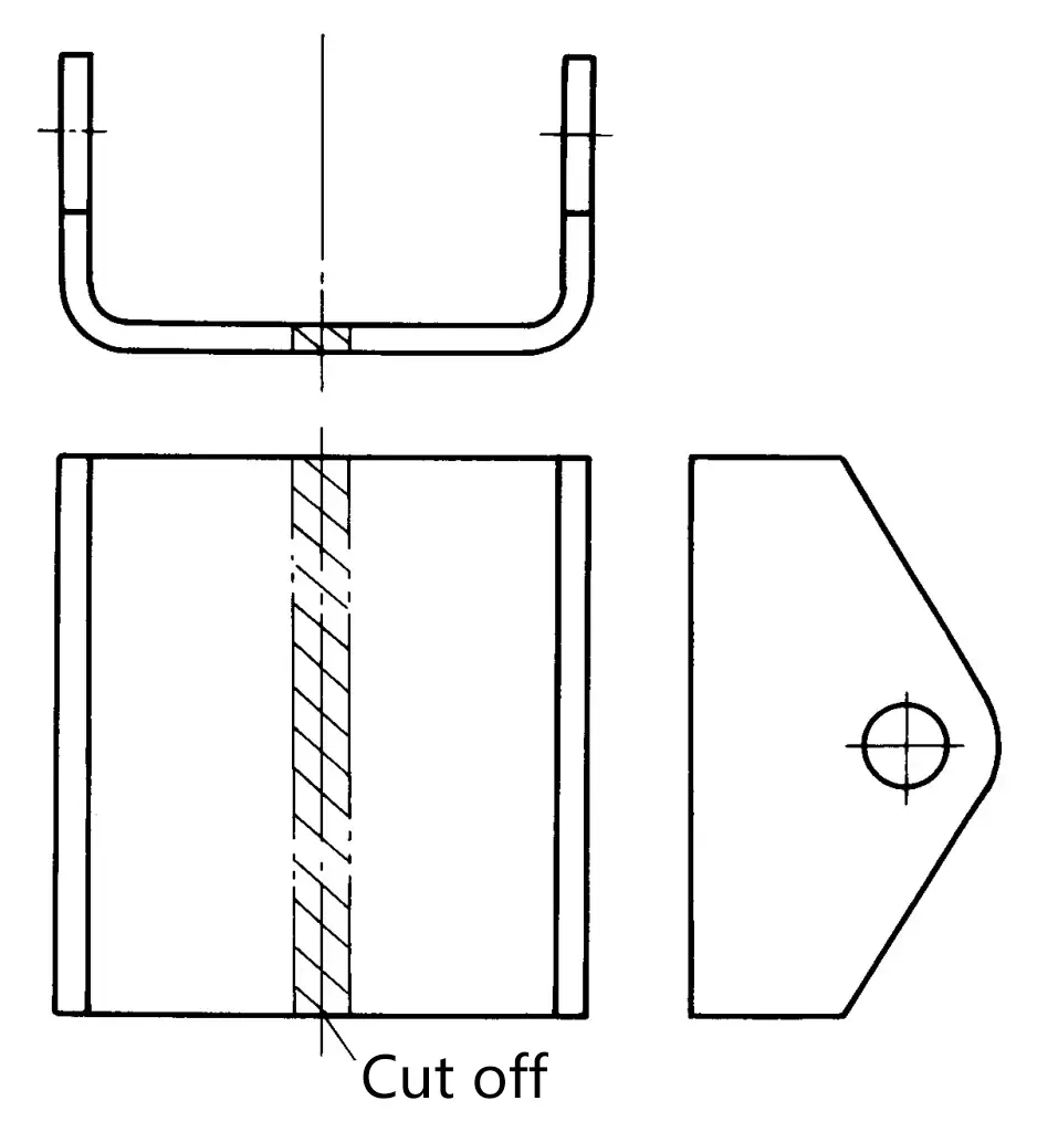
(3) When the height of the bent edge must be less than the “minimum bending edge height” due to structural reasons, a method of initially increasing the height of the bending edge and then cutting off the excess material after bending can be adopted.
(4) When considering that a certain process might have a large deformation, the high-precision dimensions on the parts should be completed in the later processes.
(5) For asymmetrically bent parts, the asymmetric shape of the bent parts can be combined into a symmetrical shape, and the method of bending in pairs and then cutting them apart can be adopted.
(See Figure 1), in this way, the blank is evenly stressed during bending, which is conducive to overcoming offset.
1. In mold design, use a blank holder device to gradually bend the blank into shape under a pressed state.
2. In mold design, use reasonable positioning plates (external positioning) or positioning pins (hole positioning), and if necessary, add process hole positioning to ensure reliable positioning of the blank in the mold, and that it does not detach from the positioning parts during the bending process.
3. Consider measures to eliminate springback in the mold structure (refer to Section 3), and consider the possibility of mold adjustment and maintenance.
4. In order to reduce springback and defects such as uneven bottoms, the workpiece should be corrected in the mold at the end of the stroke, that is, the die or pressure plate should be in a “coined” state.
5. For U-shaped bends, a smaller clearance or even negative clearance (z<t) bending can be used.
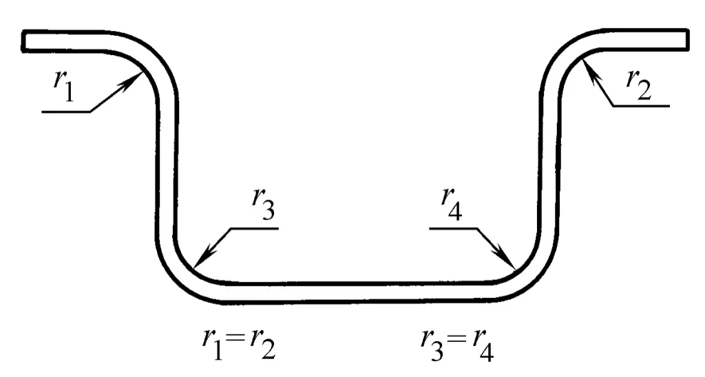
6. When manufacturing and adjusting molds, pay attention to the consistency of the fillet radius size and surface roughness of the symmetrical parts of the punch and die (see Figure 2).