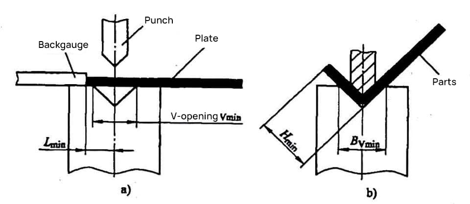
The key factor affecting the bend height of the bending machine is the groove width of the die. The minimum bend height in V-bending is shown in Figure 1. The starting state of a simple V-bending is shown in Figure 1a.
From the figure, we can see that when the bending allows the minimum dimension Lmin from the bending line (symmetrical line of the die groove) to the edge of the sheet to be bent, the minimum limit dimension of the bending machine bend height, or the minimum bend height Hmin, is as shown in Figure 1b.
Therefore, the minimum bend height of the bending machine is determined by the groove width of the die.

1) We can determine the minimum value Bvmin of the die groove width required for bending of different sheet thicknesses t according to formula (2-1).
Example 2-1:
Calculate the minimum die groove width Bvmin that can be used when bending a material with a sheet thickness t=1.5mm.
Solution: Take Kb=6, substitute t=1.5mm into formula (2-1), and get Bvmin = 6 x 1.5mm = 9mm. Compare with the specifications of the die groove width above, and you can choose a lower die with a groove width of 10mm (or 8mm).
2) From the starting state diagram of bending, we can see that the minimum dimension Lmin from the bend line (symmetrical line of the die groove) to the edge of the sheet is limited by the minimum value Bvmin of the groove width. Lmin must be greater than Bvmin/2. Through experiments, it is proven that:
Lmin= Bvmin/2 + f (2-2)
Where f is an empirical value (mm), usually take f>0.5~1.
3) The relationship between the minimum dimension Lmin from the bend line (symmetrical line of the die mouth) to the edge of the sheet in V-bending (90°) and the minimum bend height H is as follows:
Hmin=Lmin+t-x/2.
Substituting formula (2-2) into this formula gives the calculation formula for the minimum bend height in V-bending:
Hmin=(Bvmin-x)/2+f+t (2-3)
Where Hmin is the minimum bend height (mm); x is the correction value of the bending R part (mm). When φ=90° bending does not use the pressure plate, see Table 1 for the correction value of the R part. When φ=90° bending uses the pressure plate, see Table 2-2 for the positive value of the R part.
Table 1 Correction value x of the R part when φ=90° bending does not use the pressure plate (unit: mm)
| Bending radius r | Material thickness t | |||||||||||||
| 0.3 | 0.5 | 0.8 | 1 | 1.5 | 2 | 2.5 | 3 | 3.5 | 4 | 4.5 | 5 | 5.5 | 6 | |
| 0.25 | 0.08 | 0.1 | 0.27 | 0.38 | / | / | / | / | / | / | / | / | / | |
| 0.5 | 0.13 | 0 | 0.17 | 0.28 | 0.56 | / | / | / | / | / | / | / | / | / |
| 0.75 | 0.23 | 0.11 | 0.06 | 0.18 | 0.46 | 0.76 | / | / | / | / | / | / | / | / |
| 1 | 0.33 | 0.22 | 0.04 | 0.07 | 0.36 | 0.68 | 1 | / | / | / | / | / | / | / |
| 1.25 | 0.44 | 0.32 | 0.14 | 0.03 | 0.26 | 0.58 | 0.92 | 1.27 | / | / | / | / | / | / |
| 1.5 | 0.54 | 0.43 | 0.25 | 0.13 | 0.16 | 0.5 | 0.84 | 1.2 | 1.58 | / | / | / | / | / |
| 1.75 | 0.64 | 0.53 | 0.35 | 0.22 | 0.07 | 0.4 | 0.75 | 1.12 | 1.51 | 1.87 | / | / | / | / |
| 2 | 0.74 | 0.64 | 0.46 | 0.32 | 0.01 | 0.32 | 0.66 | 1.04 | 1.44 | 1.81 | 2.14 | / | / | / |
| 2.5 | 0.96 | 0.85 | 0.67 | 0.54 | 0.24 | 0.12 | 0.47 | 0.87 | 1.28 | 1.65 | 2 | 2.3 | 2.58 | |
| 3 | 1.18 | 1.06 | 0.87 | 0.75 | 0.44 | 0.07 | 0.29 | 0.7 | 1.1 | 1.49 | 1.85 | 2.16 | 2.48 | 2.64 |
| 3.5 | 1.41 | 1.28 | 1.09 | 0.97 | 0.65 | 0.29 | 0.09 | 0.51 | 0.92 | 1.31 | 1.68 | 2.01 | 2.38 | 2.5 |
| 4 | 1.66 | 1.54 | 1.33 | 1.2 | 0.87 | 0.51 | 0.19 | 0.3 | 0.71 | 1.12 | 1.5 | 1.84 | 2.16 | 2.32 |
| 4.5 | 1.93 | 1.78 | 1.58 | 1.44 | 1.11 | 0.75 | 0.34 | 0.08 | 0.48 | 0.92 | 1.3 | 1.64 | 1.98 | 2.3 |
| 5 | 2.22 | 2.06 | 1.88 | 1.73 | 1.4 | 1.03 | 0.62 | 0.22 | 0.22 | 0.66 | 1.04 | 1.4 | 1.74 | 2.08 |
Note:
- Data to the left of numbers with shadows is negative (-) and should be subtracted from the equation.
- Data to the right of numbers with shadows is positive (+) and should be added to the equation.
- When bending with a press brake, calculations can be made according to this table.
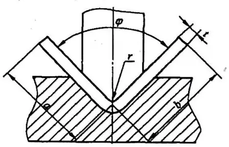
- Dimensional annotation examples are shown in Figure 2.
- The formula for calculating unfolded dimensions is: L = a + 6 + x, where:
- a refers to the edge length excluding material thickness (mm),
- b refers to the edge length excluding material thickness (mm),
- x is the correction value for the R portion (mm).

Table 2 When φ=90° and a press plate is used for bending, the correction value x for the R portion (Unit: mm)
| Bending radius r | Material thickness t | |||||||||||||
| 0.3 | 0.5 | 0.8 | 1.0 | 1.5 | 2.0 | 2.5 | 3.0 | 3.5 | 4.0 | 4.5 | 5.0 | 5.5 | 6.0 | |
| 0.25 | 0.03 | 0.17 | 0.27 | 0.53 | 0.82 | 1.08 | 1.37 | 1.67 | 1.92 | 2.15 | 2.36 | 2.54 | 2.73 | |
| 0.50 | 0.13 | 0.10 | 0.20 | 0.46 | 0.74 | 1.02 | 1.31 | 1.60 | 1.87 | 2.11. | 2.33 | 2.52 | 2.68 | |
| 0.75 | 0.22 | 0.03 | 0.13 | 0.38 | 0.67 | 0.95 | 1.25 | 1.55 | 1.82 | 2.05 | 2.28 | 2.48 | 2.65 | |
| 1.00 | 0.30 | 0.20 | 0.32 | 0.60 | 0.89 | 1.17 | 1.48 | 1.76 | 2.00 | 2.24 | 2.42 | 2.62 | ||
| 1.25 | 0.38 | 0.28 | 0.13 | 0.23 | 0.52 | 0.81 | 1.10 | 1.40 | 1.68 | 1.95 | 2.18 | 2.40 | 2.56 | |
| 1.50 | 0.46 | 0.37 | 0.22 | 0.16 | 0.45 | 0.73 | 1.12 | 1.34 | 1.63 | 1.83 | 2.31 | 2.35 | 2.52 | |
| 1.75 | 0.56 | 0.46 | 0.30 | 0.07 | 0.37 | 0.66 | 0.96 | 1.27 | 1.55 | 1.83 | 2.07 | 2.30 | 2.46 | |
| 2.00 | 0.64 | 0.54 | 0.38 | 0.28 | 0.29 | 0.58 | 0.88 | 1.18 | 1.48 | 1.75 | 2.00 | 2.24 | 2.33 | |
| 2.50 | 0.82 | 0.72 | 0.56 | 0.46 | 0.10 | 0.41 | 0.70 | 1.02 | 1.33 | 1.60 | 1.87 | 2.10 | 2.19 | |
| 3.00 | 1.00 | 0.92 | 0.76 | 0.66 | 0.40 | 0.22 | 0.52 | 0.85 | 1.16 | 1.44 | 1.72 | 1.96 | 2.05 | |
| 3.50 | 1.20 | 1.10 | 0.94 | 0.83 | 0.57 | 0.03 | 0.35 | 0.67 | 0.98 | 1.27 | 1.55 | 1.80 | 1.88 | |
| 4.00 | 1.40 | 1.30 | 1.14 | 1.04 | 0.77 | 0.48 | 0.16 | 0.48 | 0.80 | 1.10 | 1.38 | 1.63 | 1.72 | |
| 4.50 | 1.60 | 1.48 | 1.33 | 1.23 | 0.95 | 0.67 | 0.36 | 0.30 | 0.61 | 0.90 | 1.20 | 1.45 | 1.54 | |
| 5.00 | 1.78 | 1.68 | 1.53 | 1.43 | 1.16 | 0.87 | 0.56 | 0.10 | 0.42 | 0.73 | 1.00 | 1.27 | 1.50 | |
Note:
- The number on the shaded (inclusive) left is negative (-), which should be subtracted from the formula.
- The data on the right of the shaded number is a positive (+) value, which should be added to the formula.
- When a push plate fixture is used on the bending machine, this table can be used for calculation.
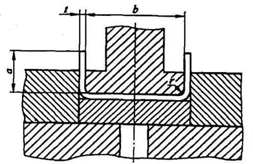
- An example of dimensional annotation is shown in Figure 3.
- The unfolding size calculation formula: L=2a+b+2x
In the formula a— edge length excluding material thickness (mm);
- b- edge length excluding material (mm);
- x- correction value of the R part (mm).

Example 2-2 Using a lower die with a groove width of 10mm and a bending knife of r0=1 on the upper die, bend a V-shaped part with a plate thickness of t=1.5mm and φ=90°. Calculate the minimum bending edge height Hmin for machining this part on the folding machine (as shown in Figure 1b).
[Solution] From formula (2-3), the minimum bending edge height of the part is
Hmin=[10-0.36)/2+0.5+1.5]mm=6.82mm
4) Recommended minimum bending edge height for cold rolled thin steel plate, see Table 3.
Table 3 Recommended Minimum Bending Edge Height (Unit: mm)
| Serial Number | Material Thickness t | V-die Slot Width Bv | Bending Knife Edge Radius r0 | Minimum Bend Height Hmin |
| 1 | 0.5 | 4 | 0.2 | 3 |
| 2 | 0.6 | 4 | 0.2 | 3.2 |
| 3 | 0.8 | 5 | 0.8 or 0.2 | 3.7 |
| 4 | 1.0 | 6· | 1 or 0.2 | 4.4 |
| 5 | 1.2 | 8(or 6) | 1 or 0.2 | 5.5(or 4.5) |
| 6 | 1.5 | 10(or 8) | 1 or 0.2 | 6.8(or 5.8) |
| 7 | 2.0 | 12 | 1.5 or 0.5 | 8.3 |
| 8 | 2.5 | 16(or 14) | 1.5 or 0.5 | 10.7(or 9.7) |
| 9 | 3.0 | 18 | 2 or 0.5 | 12.1 |
| 10 | 3.5 | 20 | 2 | 13.5 |
| 11 | 4.0 | 25 | 3 | 16.5 |
Note:
- The minimum bending edge height includes the thickness of the material.
- When the central angle α of the V-shaped bend is <90°, the minimum bending edge height needs to be increased by 0.5~1mm; when the central angle α of the V-shaped bend is >90°, the minimum bending edge height can be appropriately reduced.
- When the part material is aluminum and stainless steel, the minimum bending edge height will have some small changes. The aluminum will be slightly smaller, and the stainless steel will be slightly larger.
- The data in the table are empirical data and are for reference only.

