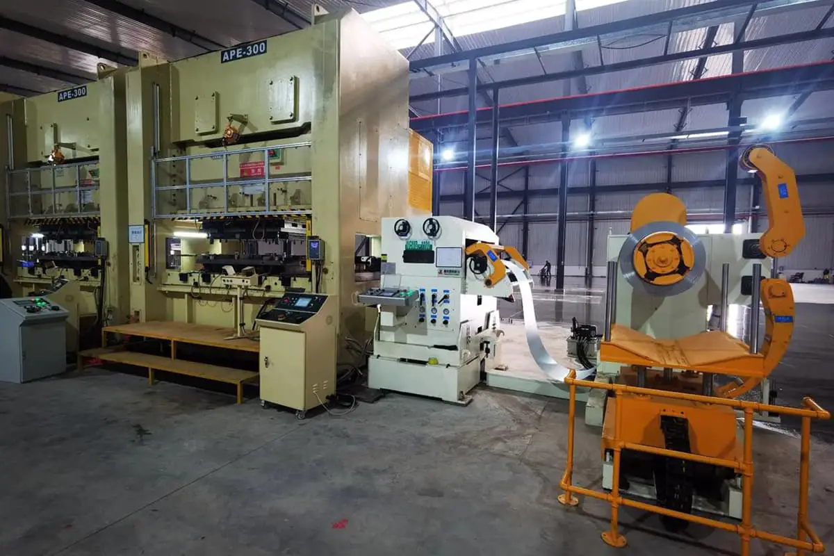
1. Introduction to Sheet Metal Fabrication
1.1 Definition:
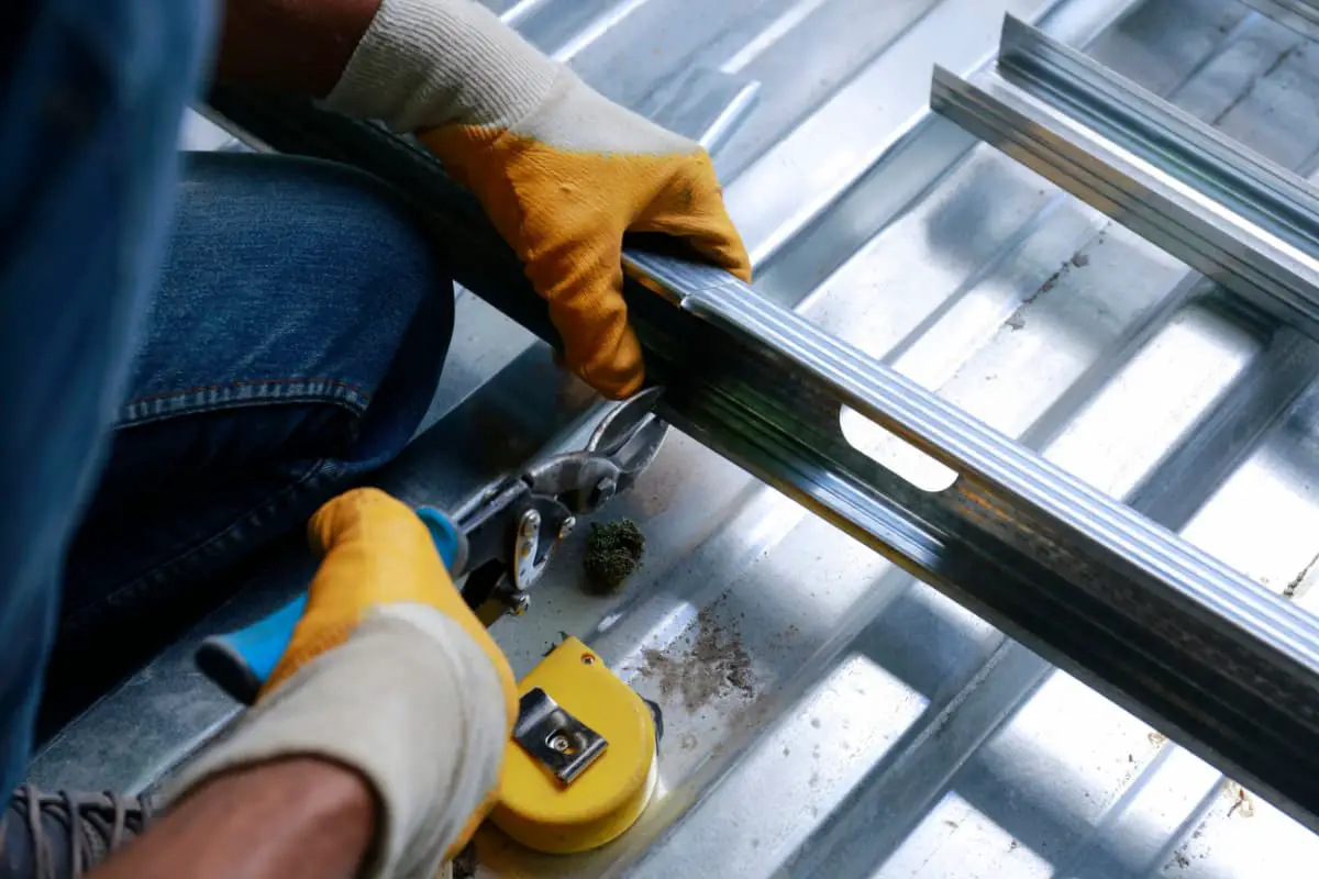
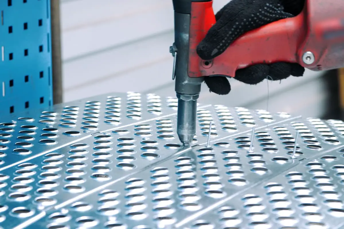
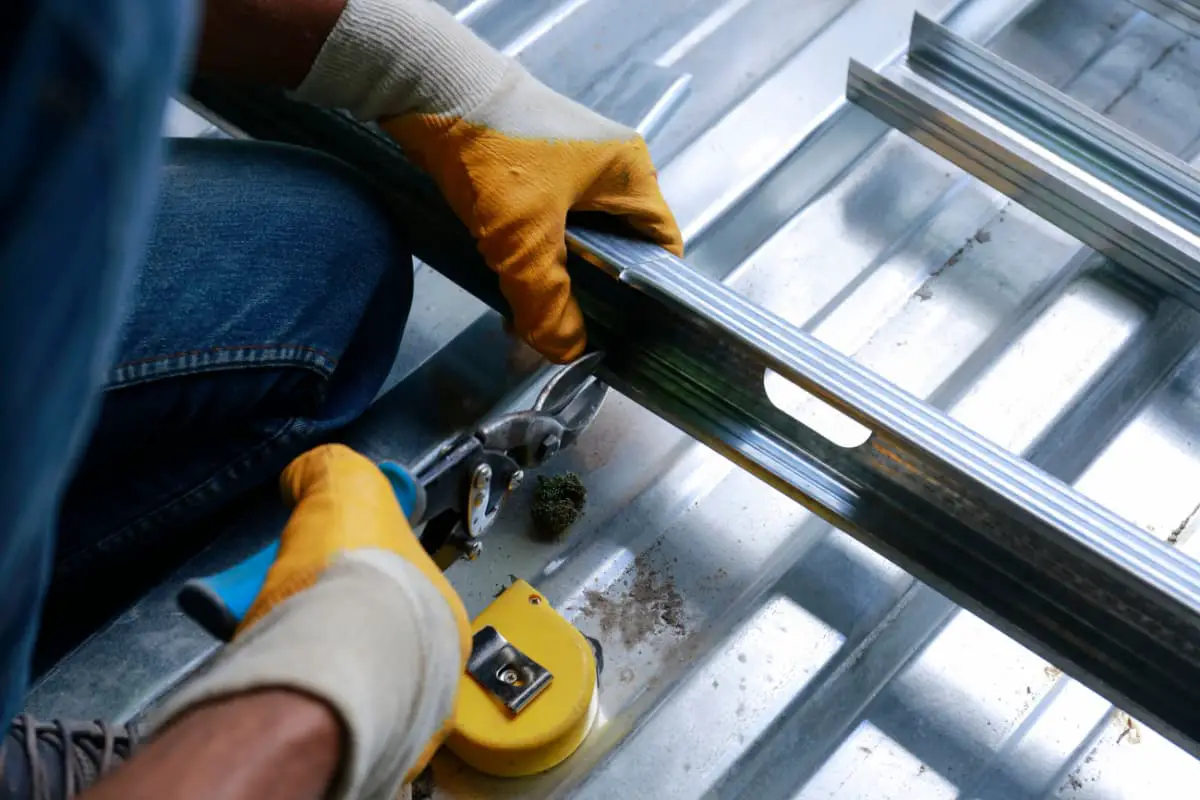
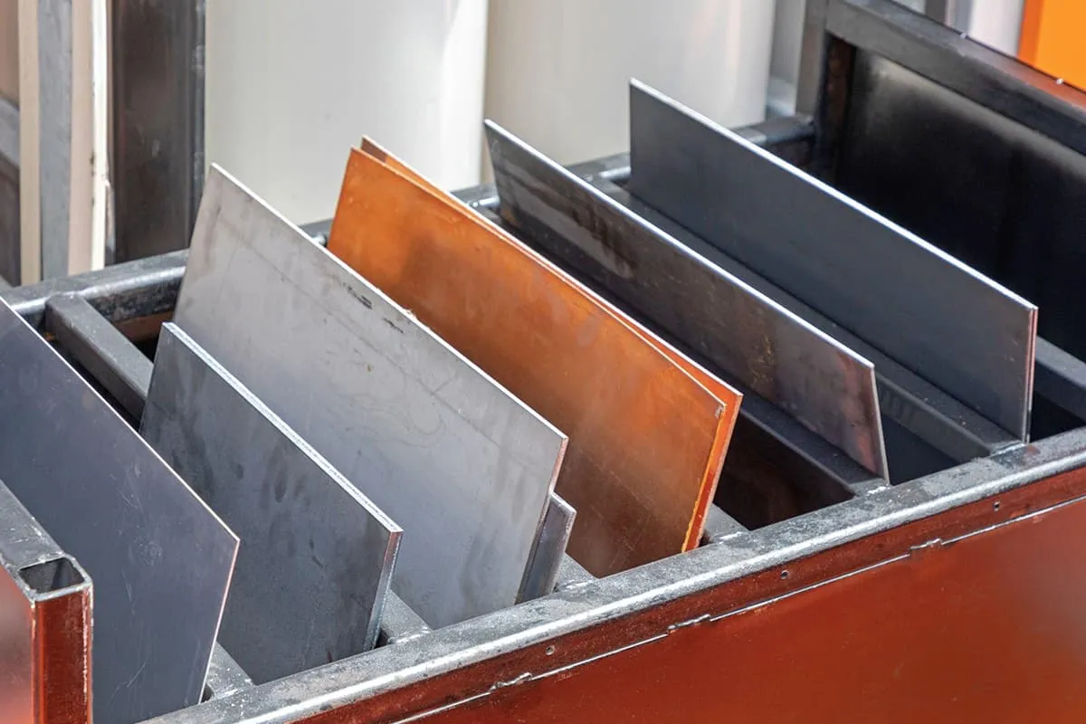
There is not yet a complete definition for sheet metal fabrication. According to a definition from a professional journal overseas, it can be defined as a comprehensive cold-working process for metal sheets (usually below 6mm), including shearing, punching/cutting/compound, folding, welding, riveting, assembling, forming (such as automobile bodies), etc. Its significant feature is that the thickness of the same part is consistent, and it processes metal sheets such as steel plates, aluminum plates, copper plates, etc.
1.2 The Process Flow of Sheet Metal Fabrication:
For any sheet metal part, it has a certain processing process, which is called the process flow. For sheet metal parts with different structures, the process flow may also be different. Combining with our company’s situation, the general process is as follows:
Customer Order → Preparation of Drawings → Drawing Unfolding (Numerical Control Programming) → Cutting (Numerical Punching) → Common Punching → Bending → Press Riveting → Welding.
Related reading: Top Equipment for Sheet Metal Fabrication: A Guide
2. Basic Knowledge of Sheet Metal Engineering Drawing
2.1 Introduction to Mechanical Drawing:
The engineering drawing for sheet metal fabrication belongs to the category of mechanical drawing. Mechanical drawing is a discipline that uses patterns to accurately represent the structural shape, size, working principle, and technical requirements of machinery.
Patterns are composed of graphics, symbols, text, numbers, etc. They are technical documents that express design intent, manufacturing requirements, and exchange experience, and are commonly called the language of the engineering industry.
The items stipulated in the mechanical drawing standards include: drawing format and format, scale, font, and lines, etc. The drawing format and format specify the size of the standard drawing format and the corresponding size of the frame in the drawing. Scale refers to the ratio of the length of the dimension in the pattern to the actual size of the machine part.
Except for drawing at a 1:1 scale, only the reduction and enlargement ratios specified in the standards are allowed. In China, it is stipulated that Chinese characters must be written in long imitation Song typeface, and letters and numbers must be written in the prescribed structure.
Eight types of lines are specified for drawing, such as bold solid lines for visible contour lines, dotted lines for invisible contour lines, fine dot-dashed lines for axis and symmetry center lines, and thin solid lines for dimension and section lines, etc.
Mechanical drawings mainly include part drawings and assembly drawings. Part drawings express the shape, size, manufacturing, and inspection technical requirements of parts; assembly drawings express the assembly relationships and working principles between the parts and components belonging to the machinery; and graphically express the structure and shape of the parts, commonly used views include a front view, sectional view, and section view, etc.
Views are graphic shapes obtained by projecting parts onto the projection plane according to the orthographic projection method. Depending on the projection direction and the position of the corresponding projection plane, views are divided into main views, top views, and left views, etc. Views are mainly used to express the external shape of the machine parts. The contour lines that cannot be seen in the figure are represented by dotted lines.
When projecting a part onto a projection plane, there are two relative positions between the observer, the part, and the projection plane. When the part is located between the projection plane and the observer, it is called the first-angle projection method. When the projection plane is located between the part and the observer, it is called the third-angle projection method. Both projection methods can equally well express the shape of the machine parts. Chinese national standards stipulate the use of the first-angle projection method.
2.2 Introduction to Orthographic Projection
Orthographic projection is a drawing method that accurately represents the geometry, size, and shape of an object by projecting its outline onto a plane.
An object has six views: a front view, which reflects the shape of the front of the object when projected from the front; a top view, which reflects the shape of the top of the object when projected from above; a left view, which reflects the shape of the left side of the object when projected from the left side, and three other views that are not commonly used.
The three main views – front, top, and left – together are called the orthographic projection or multiview projection.
Each view can only show the shape of one direction of the object and cannot fully reflect the structural shape of the object. Three-view drawings are the result of projecting the same object from three different directions. In addition, auxiliary views such as sectional views and half-sectional views are used to fully express the structure of the object.
The projection rules for orthographic projection are:
- Front view and top view- Length dimension line is aligned.
- Front view and left view- Height dimension line is aligned.
- Left view and top view- Width dimension line is aligned.
2.3 Drawing Recognition Method
When looking at a three-view drawing, how can we understand its spatial shape? This is a process from two-dimensional to three-dimensional space. Sheet metal drawings are relatively simple, and a basic method of viewing it is introduced here – form analysis.
Form analysis involves analyzing which basic shapes make up the object, finding the projection of each basic shape, visualizing their spatial shape, and then combining the basic shapes and their relative positions to visualize the overall spatial shape.
Since each view can only show the shape of one direction of the object, multiple views must be combined to fully understand the object’s structure. For more complex objects, three views alone may not be enough to clearly express their shape.
Additional projection views, such as the right view, top-back view, rear view, or auxiliary views such as sectional views, section views, and local enlargement views may be required.
2.4 Introduction to Third Angle Projection
There are two ways to draw a three-view drawing: third-angle projection and first-angle projection, both of which comply with the ISO international standard.
Currently, China, Germany, and other countries use the first-angle projection method, while the United States, Japan, and other countries use the third-angle projection method. In the actual production process, we also often see drawings using the third-angle projection method.
The difference between the two projection methods is:
The first-angle projection method places the object between the observer and the projection plane.
The third-angle projection method places the projection plane between the observer and the object. Therefore, the views obtained by the two projection methods are opposite in representing the front-back relationship of the object:
For the first-angle projection method: the left view is placed on the right side, the right view is placed on the left side, and the top view is placed at the bottom, and so on.
For the third-angle projection method: the left view is placed on the left side, the right view is placed on the right side, and the top view is placed on the top, and so on.
To distinguish between the two projection methods, the international standard stipulates different symbols for each, as shown in the figure.

3. Sheet Metal Unfolding Calculation
3.1 Principle of Unfolding Calculation:
During the bending process of sheet metal, the outer layer is subjected to tensile stress, the inner layer is subjected to compressive stress, and there is a neutral layer between them that is neither in tension nor compression.
The length of the neutral layer remains unchanged during bending, so it serves as the reference for calculating the unfolding length of the bent part. The position of the neutral layer depends on the degree of deformation.
When the bending radius is large and the bending angle is small, the degree of deformation is small, and the neutral layer is located near the center of the thickness of the sheet metal. When the bending radius becomes smaller and the bending angle increases, the degree of deformation increases, and the position of the neutral layer gradually moves toward the inside of the bending center.
3.2 Calculation Method:
There are many ways to calculate the unfolding of sheet metal, and the calculation methods used by each sheet metal factory may not be the same. Our company uses a simple and practical deduction method to calculate the unfolding size.
The basic formula for unfolding is: Unfolding Length = Outer Dimension + Outer Dimension – Unfolding Coefficient (K Value).
| Bending Types | schematic diagram | computational formula |
| Right-Angle Bending |  | unfolded dimensions=A+B-K |
| Non-Right-Angle Bending |  | unfolded dimensions=A+B-(q/90°)*K |
| Arc Bending (R/T>5) |  | unfolded dimensions=A+B-0.43T |
| Straight Flange (Z-Bend) |  | 1. When H≧5T, it should be formed in two steps and calculated according to two right-angle bends; 2. When H<5T, it should be formed in one step, and L=A+B+K (Refer to Table 3.2.4 for the value of K). |
| Angled Flange (Z-Bend) |  | 1. When H<2T, a. When q≤70°, L=A+B+C+0.2 b. When q>70°, L=A+B+K (Refer to Table 3.2.4 for the value of K, i.e., expanded according to the difference of straight sides) 2.When H≧2T, it should be formed in two steps and calculated according to two non-right-angle bends.; |
Table 3-1 Unfolding Coefficient Table for Steel Plates (Unit: mm)
| plate thickness T | 0.8 | 1.0 | 1.2 | 1.5 | 2.0 | 2.5 | 3.0 |
| K(cold plate) | 1.5 | 1.8 | 2.1 | 2.6 | 3.4 | 4.5 | 5.4 |
| K(stainless steel) | 1.4 | 1.9 | 2.3 | 2.87 | 3.75 |
Table 3-2 Unfolding Coefficient Table for Aluminum Plates (Unit: mm)
| plate thickness T | 0.5 | 1.0 | 1.2 | 1.5 | 2.0 | 2.5 | 3.0 |
| K | 0.8 | 1.5 | 1.7 | 2.3 | 3.2 | 4.0 | 5.0 |
Table 3-3 Unfolding Coefficient Table for Copper Plates (Unit: mm)
| plate thickness T | 1.0 | 1.5 | 2.0 | 2.5 | 3.0 | 4.0 | 5.0 | 6.0 | 8.0 | 10.0 |
| K | 1.8 | 2.6 | 3.5 | 4.4 | 4.8 | 6.5 | 8.0 | 9.5 | 12.5 | 16 |
Table 3-4 Unfolding Coefficient Table for Straight Edge Difference (Unit: mm)
| H T | 0.5 | 0.8 | 1.0 | 1.2 | 1.5 | 1.6 | 2.0 | 3.2 |
| 0.5 | 0.1 | |||||||
| 0.8 | 0.2 | 0.1 | 0.1 | |||||
| 1.0 | 0.5 | 0.2 | 0.2 | 0.2 | 0.2 | 0.2 | ||
| 1.5 | 1.0 | 0.7 | 0.5 | 0.3 | 0.3 | 0.3 | 0.3 | 0.2 |
| 2.0 | 1.5 | 1.2 | 1.0 | 0.8 | 0.5 | 0.4 | 0.4 | 0.3 |
| 2.5 | 2.0 | 1.7 | 1.5 | 1.3 | 1.0 | 0.9 | 0.5 | 0.4 |
| 3.0 | 2.5 | 2.2 | 2.0 | 1.8 | 1.5 | 1.4 | 1.0 | 0.5 |
| 3.5 | 2.7 | 2.5 | 2.3 | 2.0 | 1.9 | 1.5 | 0.6 | |
| 4.0 | 3.2 | 3.0 | 2.8 | 2.5 | 2.4 | 2.0 | 0.8 | |
| 4.5 | 3.7 | 3.5 | 3.3 | 3.0 | 2.9 | 2.5 | 1.3 | |
| 5.0 | 4.0 | 3.8 | 3.5 | 3.4 | 3.0 | 1.8 |
3.3 Unfolding calculation commonly used mathematical knowledge
3.3.1 Dimension Units
The basic unit of length in China is meter (m), and the conversion relationship is:
- 1 meter (m) = 100 centimeters (cm)
- 1 centimeter (cm) = 10 millimeters (mm)
- 1 millimeter (mm) = 1000 micrometers (μm)
English units of length are used in countries such as the United Kingdom and the United States, with the following progression:
- 1 yard = 3 feet
- 1 foot (1′) = 12 inches (12″)
The conversion relationship between inches and millimeters: 1 inch (1″) = 25.4mm
3.3.2 Commonly Used Computational Formulas
| Law of Cosines | 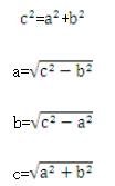 |  |
| arch size calculation | 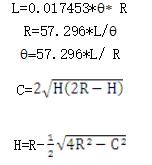 | 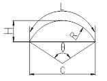 |
| calculation formulas for trigonometric functions of right triangles | sinA=a/c cosA=b/c tanA=a/b cotA=b/a |  |
4. Introduction to commonly used sheet metal materials
4.1 Introduction to commonly used plates
4.1.1 Cold-rolled ordinary thin steel plate, also known as cold plate, is a shortened name for ordinary carbon structural steel cold-rolled plate. It is made of hot-rolled steel plate of ordinary carbon structural steel and further cold-rolled into a thickness less than 4mm.
Since it is rolled at room temperature and does not produce scale, the surface quality is good, the dimensional accuracy is high, and with annealing treatment, its mechanical and process properties are good. It is the most commonly used metal material in sheet metal processing.
Common grades: National Standard GB (Q195, Q215, Q235, Q275), Japanese Standard JIS (SPCC, SPCD, SPCE)
4.1.2 Continuously electroplated galvanized thin steel plate, commonly known as electrolytic plate, refers to the deposition of zinc from a deep water solution of zinc salt onto a pre-prepared cold plate surface under the action of an electric field on the electroplating zinc production line, resulting in a layer of galvanized layer on the surface of the steel plate, giving it good corrosion resistance.
Grades: National Standard GB (DX1, DX2, DX3, DX4), Japanese Standard JIS (SECC, SECD, SECE)
4.1.3 Continuously hot-dip galvanized thin steel plate, generally referred to as galvanized sheet or white iron sheet, has a beautiful surface with block or leaf-like crystalline patterns, and the coating is firm, with excellent atmospheric corrosion resistance.
At the same time, the steel plate has good welding performance and cold forming performance. Compared to the surface of the electro-galvanized sheet, its coating is thicker, mainly used for sheet metal parts requiring strong corrosion resistance.
Grades: National Standard GB (Zn100-PT, Zn200-SC, Zn275-JY), Japanese Standard JIS (SGCC, SGCD1, SGCD2, SGCD3)
4.1.4 Stainless steel plate is a type of steel that is resistant to weak corrosive media such as air, steam, water, and chemical corrosion media such as acid, alkali, and salt. It is also called stainless acid-resistant steel. In actual use, steel that is resistant to weak corrosive media is often referred to as stainless steel, while steel that is resistant to chemical media is referred to as acid-resistant steel.
Stainless steel is usually classified according to its matrix structure:
1. Ferritic stainless steel.
Contains 12% to 30% chromium. Its corrosion resistance, ductility, and weldability increase with increasing chromium content, and its resistance to chloride stress corrosion is better than other types of stainless steel.
2. Austenitic stainless steel.
Chromium content is greater than 18%, with about 8% nickel and small amounts of molybdenum, titanium, nitrogen, and other elements. It has good comprehensive properties and can withstand corrosion by various media.
3. Austenitic-ferritic duplex stainless steel.
It has the advantages of austenitic and ferritic stainless steel and has super plasticity.
Martensitic stainless steel. High strength, but poor plasticity and weldability. It should be noted that the strength of stainless steel plate is high, and it causes greater tool wear for CNC punch presses. It is generally not suitable for numerically-controlled punching processing.
Grades: There are many types of stainless steel, and the commonly used one in sheet metal processing is a type of austenitic stainless steel (1Cr18Ni9Ti). Japanese Standard JIS (SUS)
4.1.5 Aluminum plate, aluminum is a silver-white lightweight metal with good thermal conductivity, electrical conductivity and ductility. Pure aluminum has low strength and cannot be used as a structural material. The aluminum alloy plate commonly used in sheet metal processing can be divided into eight series according to the content of alloy elements, namely 1000 series, 2000 series ~ 8000 series.
The commonly used ones are 2000 series, 3000 series and 5000 series. The 2000 series is a copper-aluminum alloy, characterized by high hardness, also known as hard aluminum; it can be used for various medium-strength parts and components. The 3000 series is a manganese-aluminum alloy with good anti-rust performance, so it is also called anti-rust aluminum. The 5000 series is a magnesium-aluminum alloy, which is characterized by low density, high tensile strength, and high elongation.
The weight of aluminum-magnesium alloy is lower than that of other series under the same area.
Common grades: 3A21 (old grade LF21), 5A02 (old grade LF2), 2A06 (old grade LY6)
4.1.6 Brass plate, brass is a common name for pure copper, which has a purple appearance and excellent electrical conductivity, thermal conductivity, ductility, and corrosion resistance. However, it is expensive and mainly used as conductive and thermal materials, generally used for parts carrying large currents in power sources. Brass has low strength and generally cannot be used as structural parts.
Grades: T1, T2, T3
4.1.7 Copper alloy plate, brass is a copper-zinc alloy with high strength and excellent cold and hot working properties, but it is prone to corrosion cracking and relatively cheap, and is widely used.
Common grades: H59, H62, H70
4.2 Calculation of the weight of commonly used plates
Basic calculation formula: Material weight = Length (m) * Width (m) * Thickness (mm) * Material density
| Material Name | Steel Plate | Stainless Steel Plate | Aluminum Plate | Purple Copper Plate | Brass Plate |
| Density | 7.85 | 7.93 | 2.71 | 8.89 | 8.5 |
4.3 Common Fastener Information
Fasteners are a general term for mechanical parts used to fasten two or more parts (or components) into one whole. Commonly used fasteners include bolts, screws, nuts, washers, pins, etc.
4.3.1 Thread Processing
Representation of common threads:
Coarse thread is represented by the letter “M” and the nominal diameter. For example, the code for coarse thread with a nominal diameter of 24mm is M24.
Fine thread is represented by the letter “M”, the nominal diameter, and the pitch, such as M24*1.5.
The formula for calculating the bottom hole diameter before tapping is: Bottom hole diameter = thread outer diameter – pitch.
This can also be directly looked up:
Table 4-1.
| Thread Specifications | M2 | M3 | M4 | M5 | M6 | M8 | M10 | M12 | M14 |
| Bottom Hole Diameter | Φ1.6 | Φ2.4 | Φ3.3 | Φ4.2 | Φ5 | Φ6.8 | Φ8.5 | Φ10 | Φ12 |
4.3.2 Structural Dimensions of Countersunk Hole for Screws
Table 4-2 Dimension of Countersunk Hole for Screws
 | d1 | M2 | M2.5 | M3 | M4 | M5 |
| d2 | Φ2.2 | Φ2.8 | Φ3.5 | Φ4.5 | Φ5.5 | |
| D | Φ4.0 | Φ5.0 | Φ6.0 | Φ8.0 | Φ9.5 | |
| h | 1.2 | 1.5 | 1.65 | 2.7 | 2.7 | |
| Minimum Preferred Sheet Thickness | 1.2 | 1.5 | 1.5 | 2.0 | 2.0 | |
| α | 90° | |||||
4.3.3 The working principle of rivet nut, rivet nut with loose proof and rivet screw is to pre-process corresponding size holes on the workpiece, and then apply pressure through equipment such as a punch press or a riveting machine, so that the teeth of the rivet nut and rivet screw are squeezed into the plate, causing plastic deformation around the hole. The deformed material is extruded into the guide groove, thereby producing a locking effect.
Table 4-3 Query Table for Processing Dimensions of Rivet Nuts, Rivet Screws, and Welding Nut Bottom Holes commonly used by our company.
| Specifications Type | M2.5 | M3 | M4 | M5 | M6 | M8 | M10 |
| Press Riveting Nut Column | Φ5.4 | Φ6.1 | Φ7.2 | Through Hole Φ8 | |||
| Blind HoleΦ8.5 | |||||||
| Press Riveting Screw | Φ2.5 | Φ3 | Φ4 | Φ5 | Φ6 | Φ8 | |
| Expansion Riveting Nut | Φ5 | Φ6 | Φ8 | Φ9 | Φ11 | Φ14 | |
| Screw with loose-proof feature | Φ5.8 | Φ6.4 | Φ8 | Φ9.5 | |||
| Welding Nut | Φ5 | Φ6 | Φ7 | Φ9 |
5. Basic Knowledge of Common Measuring Tools
Instruments used to measure the elements of mechanical parts, such as diameter and angle, are called measuring tools. There are many elements of mechanical parts, and there are also many requirements for the precision of these elements. Therefore, there are many types of measuring tools for measuring elements. The measuring tools commonly used by our company include steel tape, caliper, micrometer, universal angle ruler, etc.
Generally, the specifications of these measuring tools are represented by range and graduation value. The range is the measurement range, and the graduation value is the value of the smallest scale on the instrument. The smaller the graduation value, the more precise the measuring tool is.
Whether the measuring tool is used properly not only affects the accuracy of the measuring tool itself but also directly affects the measurement accuracy of the workpiece size and even causes quality accidents, resulting in unnecessary losses for the company. Therefore, we must attach great importance to the correct use of measuring tools, strive for excellence in measurement technology, ensure obtainment of accurate measurement results, and ensure product quality.
Here is a brief introduction to some of the measuring tools we frequently use:
5.1 Steel Tape:
Steel tape is often used in daily life and work, and it is relatively easy to use. We mainly use it to measure the length dimensions of workpieces. It is divided into Class I and Class II according to accuracy, with a graduation value of 1mm. Its accuracy is relatively low, and the length range is 3m, 5m, 10m, or longer; it is suitable for measuring the length dimensions of larger-sized workpieces with low size accuracy requirements.
5.2 Caliper:
Caliper is a commonly used measuring tool with the characteristics of simple structure, convenient use, medium accuracy, and wide range of measured sizes. It has a wide range of applications and can be used to measure the outer diameter, inner diameter, length, width, thickness, depth, and hole spacing of workpieces. According to the different reading methods and principles, there are vernier calipers, dial calipers, digital calipers, etc. The vernier caliper is commonly used by our company. Since caliper is the most commonly used measuring tool in our work, let’s focus on the principle and usage of vernier caliper:
5.2.1 Vernier calipers can be divided into single-sided calipers, double-sided calipers, three-use calipers, etc. according to their structures.
(1) Single-sided calipers have internal and external measurement jaws and can measure internal and external dimensions (Figure 1-1).

(2) Double-sided calipers have a knife-shaped external measurement jaw on the upper jaw and internal and external measurement jaws on the lower jaw, which can measure internal and external dimensions (Figure 1-2).

(3) Three-use calipers have a knife-shaped internal measurement jaw used for measuring internal dimensions; external measurement jaws with flat and knife-shaped measuring surfaces used for measuring external dimensions; and a depth gauge on the back of the ruler used for measuring depth and height (Figure 1-3).

5.2.2 Reading principle and reading method of Vernier Caliper
In order to master the correct use of vernier calipers, it is necessary to learn how to read accurately and operate correctly. The reading device of the vernier caliper is composed of the ruler body and the vernier. When the movable measuring jaw on the ruler frame is in contact with the fixed measuring jaw on the ruler body, the “0” line (referred to as the vernier zero line) on the ruler frame is aligned with the “0” line on the ruler body, and the distance between the measuring jaws is zero. During measurement, the ruler frame needs to be moved to a certain position on the scale, and the distance between the movable measuring jaw and the fixed measuring jaw is the measured size, as shown in Figure 1-4.
If the vernier zero line is exactly aligned with the scale indicating 30mm on the ruler body, what should we do if the value indicated by the vernier zero line on the ruler body is slightly larger than 30mm? In this case, the integer part of the measured size (30mm) can be read from the scale line on the ruler body to the left of the vernier zero line (indicated by the arrow in the figure), and the decimal part smaller than 1mm can be read with the help of the vernier (indicated by the ● line in the figure, which is 0.7mm). The sum of the two is 30.7mm, which is the common feature of vernier measuring instruments. Therefore, it can be seen that the key to reading a vernier caliper lies in the reading of the decimal part.

The reading method of the decimal part of the vernier is to first identify which line on the vernier aligns with a line on the ruler body. Then, multiply the order number of this line on the vernier by the reading value of the vernier, and the result is the reading of the vernier. That is, Vernier reading = Vernier reading value * Order number of alignment line on the vernier.
When reading a vernier caliper, it can be divided into three steps:
- First read the integer part: Look at the value of the scale line closest to the left of the vernier zero line on the ruler body and read the integer part of the measured size.
- Then read the decimal part: Look at the right of the vernier zero line and count which line on the vernier aligns with a line on the ruler body. Read the decimal part of the measured size by multiplying the vernier reading value by the order number of the alignment line on the vernier.
- Calculate the measured size: Add the integer and decimal parts obtained from the previous two steps, and the sum is the measured size of the caliper.
5.2.3 How to use a vernier caliper
When using the vernier caliper to measure the size of the workpiece, the following points should be noted:
(1) Before measurement, wipe the caliper clean and check whether the two measuring surfaces and measuring edges of the caliper are flat and undamaged. When the two measuring jaws are tightly attached, there should be no obvious gap, and the zero lines on the vernier and main scale should align with each other. This process is called checking the zero position of the vernier caliper.
(2) When moving the ruler frame, the movement should be smooth, without being too loose or too tight, and there should be no shaking. When fixing the ruler frame with a fixing screw, the reading of the caliper should not change. When moving the ruler frame, do not forget to loosen the fixing screw, nor should it be too loose to avoid dropping.
(3) When measuring the outer dimensions of the workpiece: the connecting line of the two measuring surfaces of the caliper should be perpendicular to the measured surface of the workpiece and should not be skewed. During the measurement, the caliper can be lightly shaken to correct the vertical position, as shown in Figure 1-5. Otherwise, if the measuring jaws are in the wrong position as shown in Figure 1-5, the measurement result “a” will be larger than the actual size “b”. First, open the movable measuring jaw of the caliper so that the measuring jaws can be freely inserted into the workpiece.
Then place the workpiece against the fixed measuring jaw, and move the ruler frame to make the movable measuring jaw contact the workpiece with a slight pressure. If the caliper has a micrometer device, you can tighten the fixing screw on the micrometer device at this time, and then turn the adjusting nut to make the measuring jaws contact the workpiece and read the size. Never adjust the two measuring jaws of the caliper to be close to or even smaller than the measured size, and force the caliper to clamp onto the workpiece. This will cause the measuring jaws to deform or wear out prematurely, causing the caliper to lose its required accuracy.


Figures 1-5: Correct and Incorrect Positions for Measuring Outer Dimensions
When measuring grooves, the measuring surface of the caliper should be used to measure with the blade edge, and it is best to avoid measuring outer dimensions with the end measuring blade and knife-shaped measuring claws. For the size of circular grooves, the knife-shaped measuring claws should be used for measurement, and the flat measuring blade should not be used for measurement, as shown in 1-6.

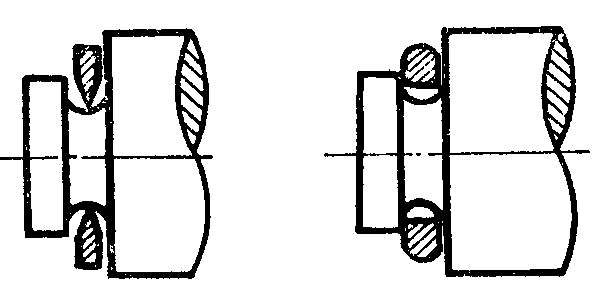
Figure 1-6: Correct and Incorrect Positions for Measuring Grooves
When measuring groove width, the position of the vernier caliper should also be adjusted properly. The connecting line between the two measuring edges of the caliper should be perpendicular to the groove and not inclined. Otherwise, if the measuring claw is in the wrong position as shown in Figure 1-7, the measurement result will be inaccurate (possibly too large or too small).
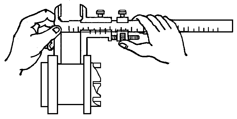


Figure 1-7: Correct and Incorrect Positions for Measuring Groove Width
(4) When measuring internal dimensions of the workpiece: as shown in Figure 1-8. The distance between the measuring claws should be smaller than the measured internal dimension. After entering the inner hole of the workpiece, slowly open and gently touch the inner surface of the workpiece. After fixing the caliper with a fixing screw, gently remove the caliper to read the measurement.
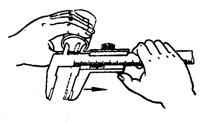
When taking out the measuring claw, the force should be even, and the caliper should slide along the centerline direction of the hole without tilting, so as to avoid twisting, deformation and unnecessary wear and tear of the measuring claws. At the same time, it will make the scale frame move and affect the measurement accuracy. The two measuring edges of the caliper should be on the diameter of the hole and not skewed.
Figure 1-9 shows the correct and incorrect positions for measuring internal holes with calipers equipped with knife-shaped measuring claws and cylindrical surface measuring claws. When the measuring claw is in the wrong position, the measured result will be smaller than the actual aperture D.

(5) When measuring internal dimensions with the external measuring surface of the lower measuring claw, the thickness of the measuring claw must be added to the measurement result when reading it. That is, the reading on the vernier caliper plus the thickness of the measuring claw is the internal dimension of the measured workpiece. The thickness of the measuring claw of the vernier caliper with a measuring range below 500mm is generally 10mm. However, when the measuring claw is worn or repaired, the thickness of the measuring claw will be less than 10mm, and this correction value should also be taken into account when reading the measurement result.
(6) When using the vernier caliper to measure a workpiece, excessive pressure is not allowed, and the pressure used should make the two measuring claws just contact the surface of the workpiece. If the measurement pressure is too high, it will not only cause the measuring claws to bend or wear out but also cause elastic deformation of the measuring claws under pressure, resulting in inaccurate measurement results (outer dimensions smaller than actual size, and inner dimensions larger than actual size).
(7) When reading the measurement result on the vernier caliper, hold the caliper horizontally and face it towards the direction of bright light, making the line of sight as perpendicular as possible to the scale surface to avoid reading errors caused by the skew of the line of sight.
(8) To obtain accurate measurement results, multiple measurements can be taken. That is, measurements are made in different directions on the same section of the workpiece. For longer workpieces, measurements should be taken at various parts of the entire length to obtain a relatively accurate measurement result.
5.3. Depth Gauge:
The depth gauge shown in Figure 1-10 is used to measure the depth of a workpiece, the height of a step, or the depth of a groove. Its structural feature is that the two measuring claws of the scale frame 3 are connected together to form a measuring base 1 with a vernier, and the end face of the base and the end face of the scale body 4 are its two measuring surfaces. When measuring the depth of an internal hole, the end face of the base should be tightly attached to the end face of the measured hole, and the scale body should be inserted parallel to the centerline of the measured hole. The distance between the end face of the scale body and the end face of the base is the depth dimension of the measured workpiece.
Its reading method is exactly the same as the vernier caliper.
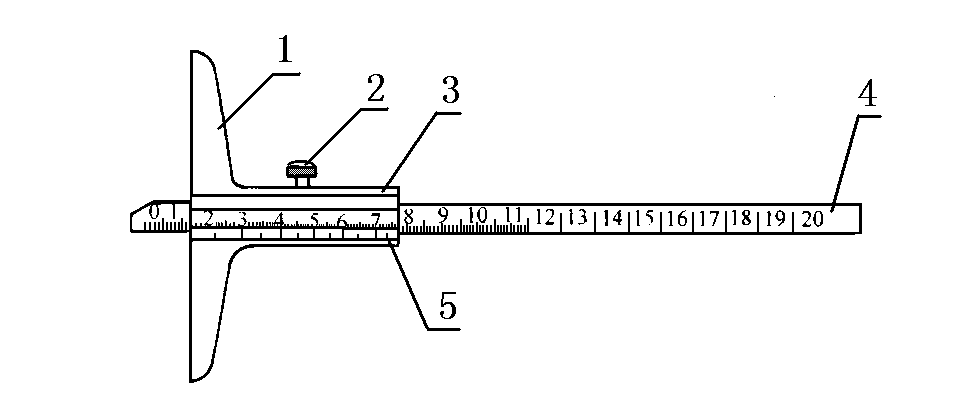
- 1- Measuring Base;
- 2- Fixing Screw;
- 3- Scale Frame;
- 4- Scale Body;
- 5- Vernier
5.4. Micrometer:
Also known as a screw micrometer, is a measuring tool made using the principle of screw micro-measurement. Its measurement accuracy is higher than that of a vernier caliper, and it is more flexible in measurement. Therefore, it is often used when high machining accuracy is required.
According to the reading resolution, it is divided into a hundredth scale and a thousandth scale. The reading value of the hundredth scale is 0.01mm, and the reading value of the thousandth scale is 0.001mm. In factories, the hundredth-scale and the thousandth-scale are commonly referred to as vernier calipers or millimeter calipers. Sheet metal fabrication mostly use hundredth-scale vernier calipers with a reading value of 0.01mm.

5.4.1 Method of using a thousandth-scale micrometer:
- Step 1: Select the appropriate range of vernier caliper according to the requirements.
- Step 2: Clean the scale body and measuring faces of the micrometer.
- Step 3: Install the micrometer on the micrometer stand, fix it, and then zero it.
- Step 4: Place the workpiece between the two working faces, adjust the thimble until the working face quickly touches the workpiece, then adjust the measuring force device until you hear three “clicks”.
5.4.2 Reading method of the thousandth-scale micrometer:
- Step 1: Read the size of the graduation line exposed on the fixed sleeve, paying attention not to miss the value of the 0.5mm graduation line that should be read.
- Step 2: Read the size on the thimble, and see which grid on the circumference of the thimble aligns with the centerline benchmark of the fixed sleeve, then multiply the number of grids by 0.001mm to get the size on the thimble.
- Step 3: Add the above two numbers to obtain the measured dimension on the vernier caliper.
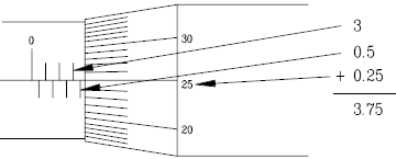
Example: As shown in the figure below, read the upper scale of the sleeve as 3, and the lower scale after 3, which means 3+0.5=3.5. Then read the sleeve scale aligned with 25, which is 25×0.001=0.025. Adding them together gives a result of 3.525.
5.5. Universal Angle Ruler:
It is an angle measuring tool used to measure internal and external angles of precision parts or to mark angles.
Method of using and reading the Universal Angle Ruler:
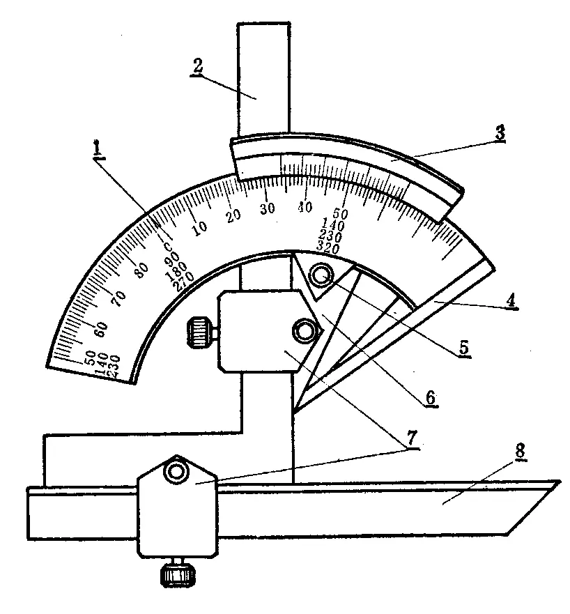
The reading mechanism of the Universal Angle Ruler, as shown in the figure on the right, is composed of a scale base 1 with basic angle graduation lines and a vernier 3 fixed on the sector plate 6. The sector plate can rotate and move on the base (with a brake 5) to form a vernier reading mechanism similar to that of a vernier caliper.
Each grid of the graduated lines on the Universal Angle Ruler has a degree of 1º. Since the vernier has 30 grids, which occupy a total angle of 29º, the degree difference between each grid line is
Thus, the accuracy of the Universal Angle Ruler is 2′.
The reading method of the Universal Angle Ruler is the same as that of the Vernier Caliper. First, read the angle before the zero line on the vernier and then read the “minute” value of the angle from the vernier. Adding the two values gives the angle value of the measured part.
On the Universal Angle Ruler, the base ruler 4 is fixed on the base, and the angle ruler 2 is fixed on the sector plate by a clamp block 7. The movable ruler 8 is fixed on the angle ruler by a clamp block. If the angle ruler 2 is removed, the straight ruler 8 can also be fixed on the sector plate. Because the angle ruler 2 and the straight ruler 8 can be moved and replaced, the Universal Angle Ruler can measure any angle from 0º to 320º, as shown in Figure 1-11.
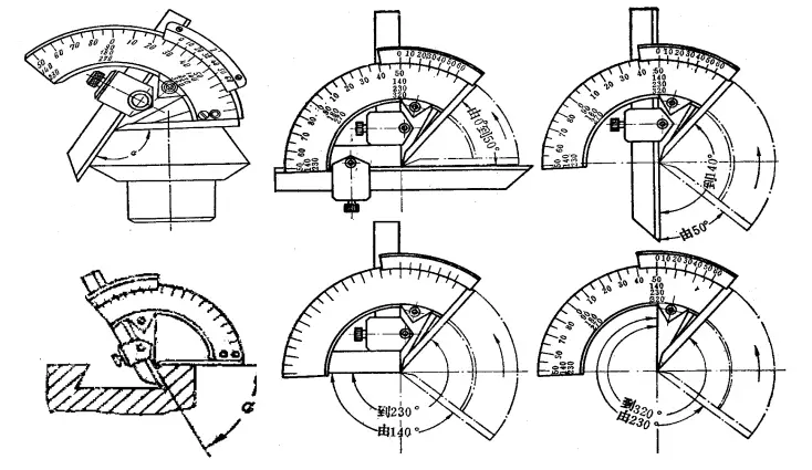
As shown in Figure 1-11, when the angle ruler and the straight ruler are fully installed, external angles from 0º to 50º can be measured. When only the straight ruler is installed, angles from 50º to 140º can be measured. When only the angle ruler is installed, angles from 140º to 230º can be measured. When both the angle ruler and the straight ruler are removed, angles from 230º to 320º can be measured (i.e., internal angles from 40º to 130º).
The basic angle graduation lines on the scale base of the Universal Angle Ruler only range from 0º to 90º. If the measured angle of the part is greater than 90º, a base value (90º, 180º, 270º) should be added to the reading. When the angle of the part is: >90º to 180º, the measured angle = 90º + the reading of the Universal Angle Ruler; >180º to 270º, the measured angle = 180º + the reading of the Universal Angle Ruler; >270º to 320º, the measured angle = 270º + the reading of the Universal Angle Ruler.
When using the Universal Angle Ruler to measure the angle of a part, the base ruler should be aligned with the baseline of the part’s angle direction, and the part should fully contact the two measuring surfaces of the angle gauge to avoid measurement errors.
6. Introduction to Main Process Technologies
6.1 Stamping Process
6.1.1 Minimum requirement for punching size Due to the strength limitation of the punching die, the aperture cannot be too small. The minimum size of the punched hole depends on the shape of the hole, material mechanical properties, and material thickness.
Table 6-1 lists the minimum hole sizes for punching.
| materials | The minimum diameter or minimum side length (t is the material thickness) for punching | ||
| Circular hole D (where D is the diameter) | Square hole L (where L is the length of each side) | Waist round hole, rectangular hole a (where a is the minimum side length) | |
| high and medium carbon steel | ≥1.3t | ≥1.2t | ≥1t |
| low carbon steel and brass | ≥1t | ≥0.8t | ≥0.8t |
| aluminum and zinc | ≥0.8t | ≥0.6t | ≥0.6t |
6.1.2 Minimum punching pitch
The minimum distance between the edge of the punched part and the outline has certain limitations depending on the shape of the part and the hole, as shown in Figure 1-12

6.1.3 Requirements for overlapping punching
The accuracy of holes and outlines, and holes and holes processed by compound dies is relatively easy to ensure, and the processing efficiency is high. However, the distance between holes and holes, and between holes and outlines, must be able to meet the minimum wall thickness requirements of the compound die, as shown in Figure 1-13
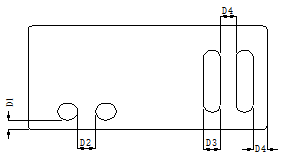
Table 6-2: Minimum size of overlapping for compound die processing of punching and blanking parts.
| t (Below 0.8) | t (0.8~1.59) | t (1.59~3.18) | t (3.2以上) | |
| D1 | 3mm | 2t | ||
| D2 | 3mm | 2t | ||
| D3 | 1.6mm | 2t | 2.5t | |
| D4 | 1.6mm | 2t | 2.5t | |
6.1.4 Punch before bending to ensure that the holes are not deformed. The minimum distance between the holes and the bent edges is shown in Figure 1-14. The formula for this distance is X≥2t+R.

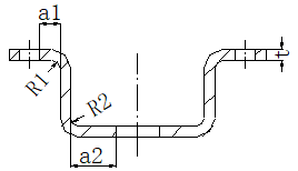
When punching holes in deep-drawn parts, as shown in Figure 1-15, in order to ensure the shape and positional accuracy of the holes and the strength of the mold, a certain distance should be maintained between the hole wall and the straight wall of the part. The distances a1 and a2 should meet the following requirements:
- a1 ≥ R1 + 0.5t
- a2 ≥ R2 + 0.5t
Where R1 and R2 are the radius of the rounding, and t is the thickness of the plate.
6.1.6 Issues and requirements to note during numerical punching:
Materials with thickness of less than 0.6mm are easy to deform, and the machining range is limited by the mold and clamp, so numerical punching is generally not suitable for use.
Materials with moderate hardness and toughness have good punching and cutting properties. If the hardness is too high, the punching force will increase, which can have a negative impact on the punch head and accuracy. If the hardness is too low, deformation during punching will be severe, which greatly limits accuracy.
High plasticity in materials is advantageous for forming processes, but may not be suitable for nibbling or continuous punching, and is not very suitable for punching and trimming. Appropriate toughness is beneficial for punching, as it can suppress the degree of deformation during punching. However, high toughness can cause serious rebound after punching, which may affect accuracy.
When stamping ordinary low-carbon steel plates, the mold diameter and width must be larger than the material thickness. For example, a mold with a diameter of Φ1.4 cannot punch a material of 1.5mm. The molds for punching aluminum alloy and copper alloy plates can be smaller, but the molds for punching stainless steel and high-carbon steel plates must be larger. Otherwise, the mold is prone to fracture and damage.
Stainless steel plates are generally not suitable for numerical punching. Of course, stainless steel plates with thicknesses of 0.8mm to 2.5mm can be processed using numerical punching, but this leads to greater wear on the mold and results in a higher scrap rate compared to ordinary steel plates.
6.2 Bending Process
Bending in sheet metal refers to the process of changing the angle of the sheet or component, such as bending a sheet metal into a V-shape, U-shape, etc. Generally, there are two methods for sheet metal bending: one is mold bending, which is used for complex structures, small volume, and large-scale production of sheet metal structures; the other is bending machine bending, which is used for processing sheet metal structures with relatively large dimensions or low production volumes. Currently, our company’s products mainly use bending machines for processing.
6.2.1 Basic principles of the bending process sequence:
- Bend from the inside to the outside;
- Bend from small to large;
- First bend special shapes, then bend general shapes;
- The forming of the previous process should not interfere with the subsequent processes.
6.2.2 Bending radius
When the material is bent, the outer layer is stretched while the inner layer is compressed in the rounded corner area. When the thickness of the material is constant, the smaller the internal radius r, the more severe the stretching and compression of the material. When the tensile stress at the outer corner exceeds the ultimate strength of the material, cracks and breakage may occur. Therefore, the structural design of bent parts should avoid small bending radii. The minimum bending radius for common materials is shown in the table below.
Table 6-1: List of minimum bending radii for commonly used metallic materials
| No. | Material | Minimum bending radius |
| 1 | 08、08F、10、10F、DX2、SPCC、E1-T52、0Cr18Ni9、1Cr18Ni9、1Cr18Ni9Ti、1100-H24、T2 | 0.4t |
| 2 | 15、20、Q235、Q235A、15F | 0.5t |
| 3 | 25、30、Q255 | 0.6t |
| 4 | 1Cr13、H62(M、Y、Y2、Cold-rolled) | 0.8t |
| 5 | 45、50 | 1.0t |
| 6 | 55、60 | 1.5t |
| 7 | 65Mn、60SiMn、1Cr17Ni7、1Cr17Ni7-Y、1Cr17Ni7-DY、SUS301、0Cr18Ni9、SUS302 | 2.0t |
- The bending radius refers to the inner radius of the bent part, with “t” being the material thickness.
- “t” represents the thickness of the material, “M” denotes annealed state, “Y” indicates hardened state, and “Y2” means half-hardened state.
6.2.3 Reference Table for Minimum Bending Edge Dimensions of Steel Plate Folding
| Material thickness | 0.8 | 1.0 | 1.2 | 1.5 | 2.0 | 2.5 | 3 |
| Minimum bending edge | 5 | 6.5(5) | 6.5(6) | 7(6.5) | 9 | 11 | 13 |
For parts with a bending dimension requirement smaller than the above-stated specifications, a separate mold should be used for processing.
6.2.4 Minimum Distance from Holes and Elliptical Holes to Bending Edges:
As shown in Figure 1-16, if the hole edge of the bending area is too close to the bending line, the material cannot be uplifted during bending, resulting in deformation of the hole shape. Therefore, the distance between the hole edge and the bending line must be greater than the minimum hole edge distance X≥t+R.
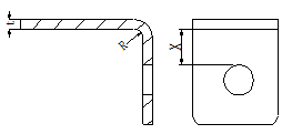
Table 6-2: Minimum Distance from Round Holes to Bending Edges.
| Material thickness | 0.6~0.8 | 1.0 | 1.2 | 1.5 | 2.0 | 2.5 |
| Minimum distance X | 1.3 | 1.5 | 1.7 | 2.0 | 3 | 3.5 |
As shown in Figure 1-17, if the elliptical hole is too close to the bending line, the material will be lifted during bending, resulting in deformation of the hole shape. Therefore, the distance between the hole edge and the bending line must be greater than the minimum hole edge distance according to Table 1-14.

Table 6-3: Minimum Distance from Elliptical Holes to Bending Edges.
| L | <26 | 26~50 | >50 |
| Minimum distance X | 2t+R | 2.5t+R | 3t+R |
6.2.5 Process Holes, Slots, and Notches for Bending Parts:
During the bending process, if the bent edge of the part needs to be bent to the inside edge of the blank, it is recommended to add process holes, slots, or notches to prevent tearing and distortion, as shown in Figure 1-18.

- The diameter of the process hole should be ≥t.
- The width of the process notch should be ≥t and the depth should be ≥1.5t.


